Tim Wilkinson
-
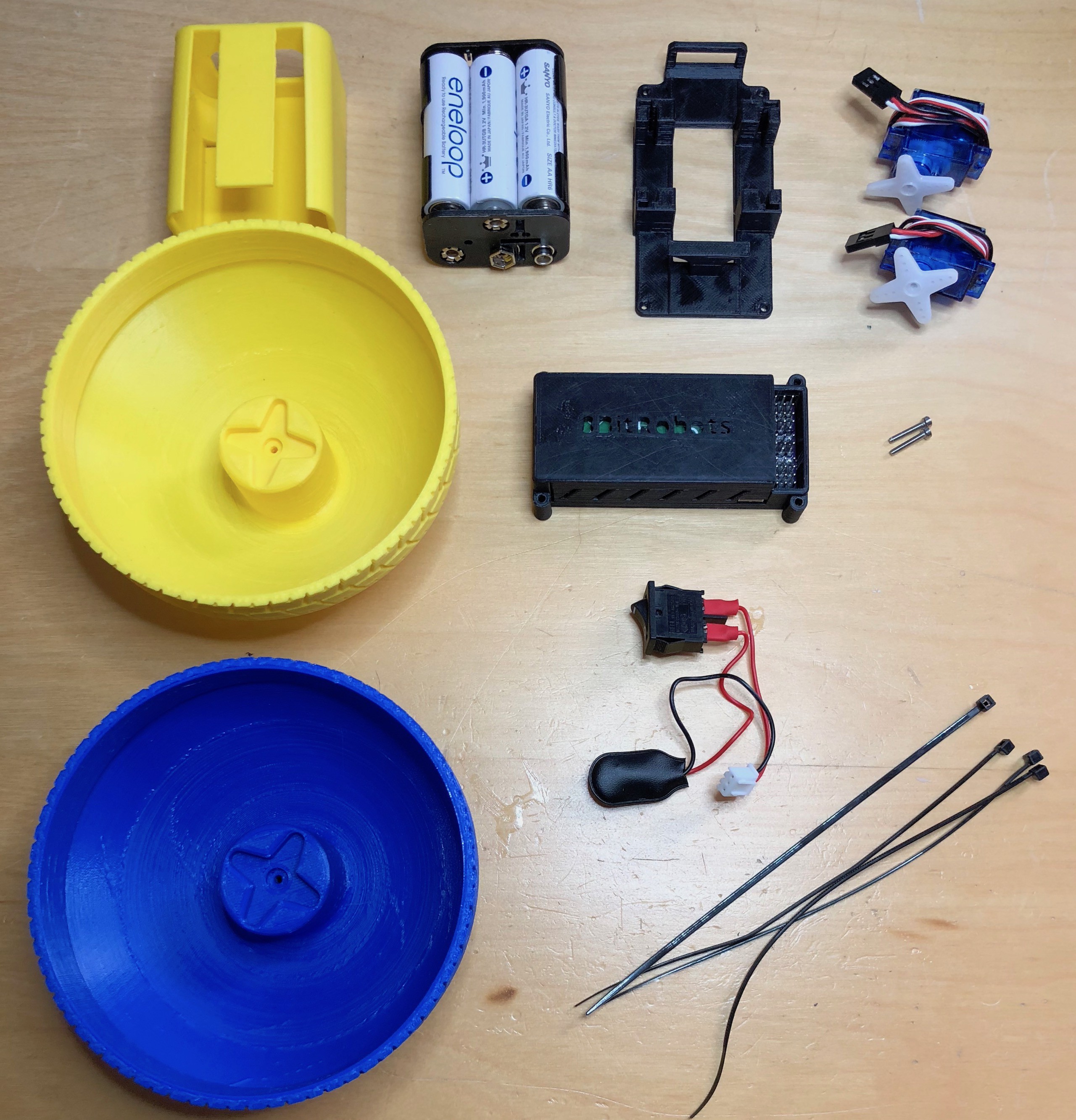
Pieces of a rolling robot
05/22/2018 at 21:17 • 0 commentsThe goal of the 8BitRobots project is to make it easy to 3D print, build and program a set of robots with only a few extra pieces. The simplest robot I could come up with ... which wasn't completely boring ... was a two wheeled rolling ball robot. I've previous logged an exploded diagram of this robots construction, but now seems like a good moment to go over all the pieces.
![]() ---------- more ----------
---------- more ----------Starting top/left:
- 1x 3D printed battery clip - used to hold the batteries inside the robot
- 6x AA batteries in holder
- 1x 3D printed robot mid-frame - to which everything else is attached
- 2x FT90R continuous servos
- 1x 3D printed robot wheel - color one
- 1x 8BitRobot module in the default 3D printed module case
- 2x M2 12mm bolts
- 1x 3D printed robot wheel - color two
- 1x Power switch, battery connector and 8BitRobots power connector
- 4x 150mm zipties
A few notes on the pieces. I selected continuous servos for the robot's motors because they were the easiest to source, use and mount. They might not be the best way to power a robot wheel, but the goal was simplicity first. I wanted to avoid using screws and bolts as much as possible. Most pieces are held together using zipties, but bolds were unavoidable when it came to attaching the wheels. Finally, the switch and power connectors was purposely constructed and really any old way to connect the batteries to the module would do.
-
Trouble with Yocto? -latomic to the rescue
05/19/2018 at 05:50 • 0 commentsIf you're following the instructions to build your own 8BitRobots distribution, you may find the compilation fails with errors like the following:
undefined reference to `__atomic_fetch_add_8'
While I'm not entirely sure why this happen, a fix is described here https://bugs.debian.org/cgi-bin/bugreport.cgi?bug=874531
The easiest way to apply this it to locate the various Makefile where the build fails, find the LIBS= directive in each one, and add -latomic to it.
LIBS = -latomic
Restart and the compilation should move on.
-
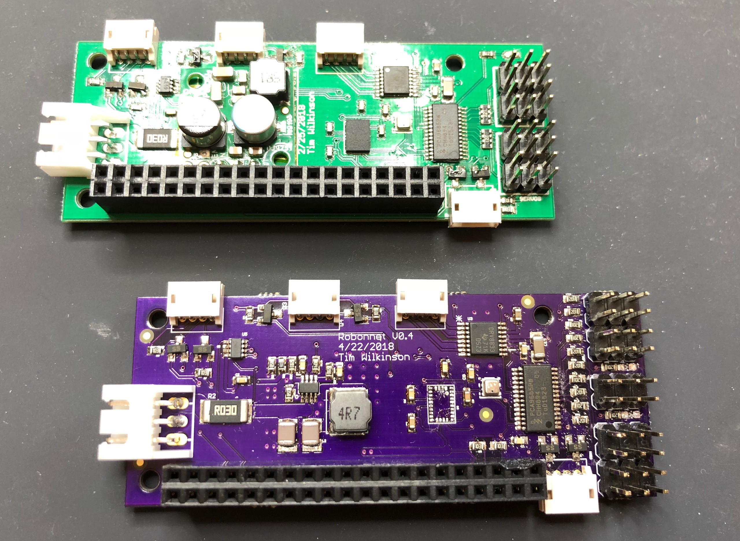
RoBonnet v0.4 - Fully assembled
05/11/2018 at 21:28 • 0 commentsFinally assembled the full RoBonnet v0.4 today (seen here with the previous version above).
![]() ---------- more ----------
---------- more ----------The major changes on this version where the integration of the buck converter and the expansion of the PWM outputs to 10 (from the original 8). Preliminary testing has been excellent, the board running the ball robot without a hitch.
Note the absence of the IMU from this test board. I did *try* to include it but it failed. I hate assembling the BNO055 (I think I get about 1 in 3 to work) and find it very tricky to work with. However, the layout for it is unchanged from the previous board where it operated flawlessly.
The next step for the hardware is to have some board professionally made. I'm thinking of using MacroFab.
-
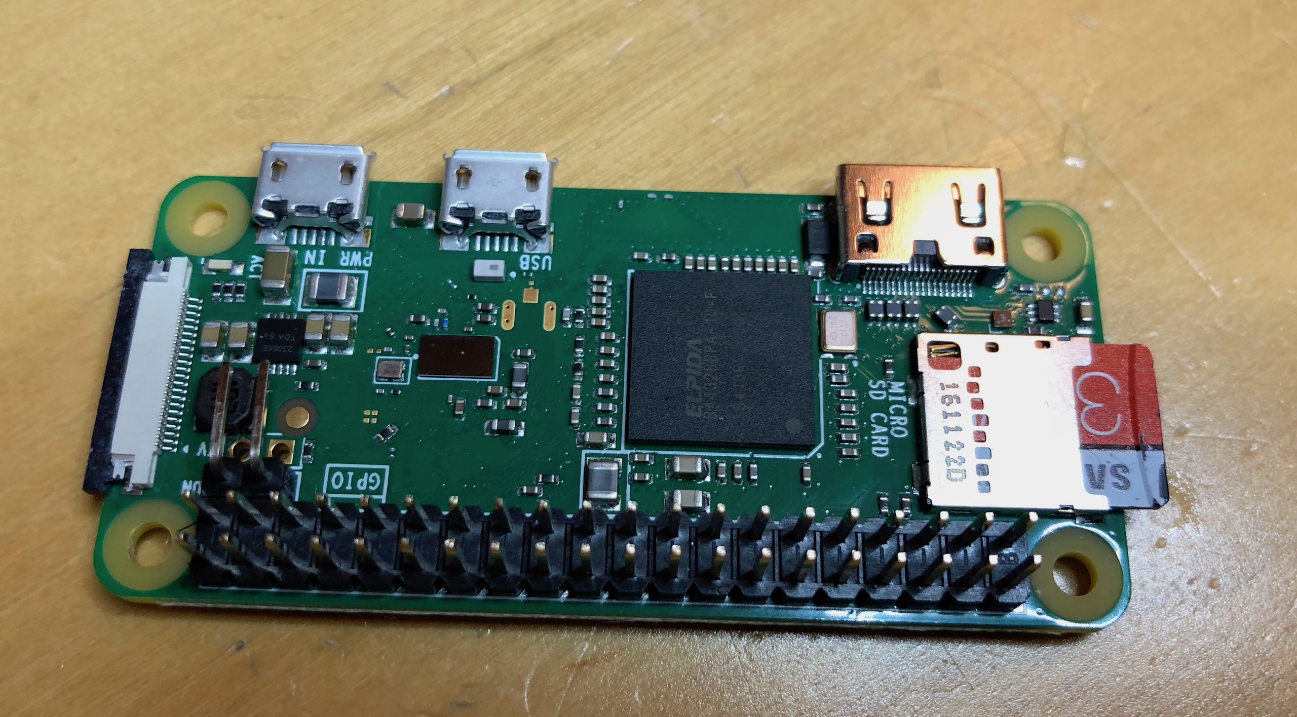
Setting up Yocto for Raspberry Pi Zero
05/09/2018 at 07:06 • 0 commentsYou can download the 8BitRobots Javascript software onto your favorite Raspberry Pi Linux installation. Alternatively, you can build a custom distribution which contains all the software bits you need, only the bits you need, and everything configured to "go" as soon as the Pi boots up. I built my distribution using these excellent instructions (https://raspinterest.wordpress.com/2016/11/30/yocto-project-on-raspberry-pi-3/) but I have enough tweaks that I thought it best to list the steps out for others.
![]() ---------- more ----------
---------- more ----------- I built my distribution on Ubuntu Linux, so I'm assuming this as a base. There's nothing here Ubuntu specific, so other Linux variants should be fine.
- Create a directory to download source:
mkdir -p ~/rpi/sources- Cd into directory
cd ~/rpi/sources- Download the layers we'll need. Yocto distributions are built using a number of "layers"
git clone -b rocko git://git.yoctoproject.org/poky git clone -b rocko git://git.openembedded.org/meta-openembedded git clone -b rocko git://git.yoctoproject.org/meta-raspberrypi git clone https://github.com/imyller/meta-nodejs.git git clone https://gitlab.com/8bitrobots/meta-8bitrobots.git git clone https://github.com/OSSystems/meta-browser.git- Create a build configuration
cd ~/rpi
source sources/poky/oe-init-build-env rpi-build
- You will now be in the directory ~/rpi/rpi-build
- Copy the example config files into the conf directory:
cp ~/rpi/sources/meta-8bitrobots/example-config/bblayers.conf conf/bblayers.conf
cp ~/rpi/sources/meta-8bitrobots/example-config/local.conf conf/local.conf
- Build the image
bitbake rpi-hwup-image
- The first time this will take a long time ... a very long time ... even on big machine it will take many, many hours. Be warned.
- Once completed you will have many things, but the one we need right now is a compressed disk image to write to an SD card. I copy it to the home directory to make it easier to find later
cp tmp/work/raspberrypi0_wifi-poky-linux-gnueabi/rpi-hwup-image/1.0-r0/deploy-rpi-hwup-image-image-complete/*.gz ~
- Now use your favorite flash tool to write it to an SD card.
-
Blockly - Activities
05/09/2018 at 05:45 • 0 commentsAlthough I've chosen Blockly as the visual programming language for 8BitRobots, I've been toying with various application styles for writing code. The Arduino style is very appealing; set stuff up then run continually until the power goes away. In Blockly this looks something like this:
![]() ---------- more ----------
---------- more ----------Above we have two Activites each with a setup and then an activity. Neither here has a setup, but any blocks would be run once before any activity loops starts. The activity loops continually, but unlikes an Arduino program, only run when changes in the system are detected. To eliminate timing issues and races, the observed state of the system is constant during the execution of each activity loop, and to keep things optimal, the activities only run when relevant changes are detected (ie. if the code doesn't read the output of the IMU, then it won't run when it changes).
Code generation is a little more complex than traditional Blockly with the visual program being split into a set of Javascript configuration and activity pieces. Additionally, because writing to hardware services is an inherently asynchronous operation (the hardware may be physically separate from where the code runs), the code makes use of the Javascript async/await/promise mechanisms (Node 7+). Ultimately this is all hidden from the Blockly developer.
VM.runInNewContext(
 code,
 {
  App:
  {
   registerActivity: (activity) => { this._registerActivity(activity); },
   registerConfiguration: (configuration) => { this._registerConfiguration(configuration); },
   run: () => { this._runApp(); },
   get: (topicName, key) => { return this._getTopicValue(topicName, key); },
   subscribe: (topicName) => { this._subscribeToTopic(topicName); },
   sync: (id, status) => { return this._syncTopicUpdates(id, status); },
   status: () => { return this._status; },
   call: (serviceName, arg) => { return this._callService(serviceName, arg); },
   part: (partName, arg) => { return this._callPart(partName, arg); },
   print: (msg) => { this._debugMessage(msg); }
  }
 }
);
The compiled Blockly code is run inside a VM context which exposes a limited API to the main system. In the above sync() is what an activity calls to wait for system changes, call() is used to make changes to the hardware services, and get() reads the system state. These three calls are probably 99.9% of what a Blockly app calls. For more information see the GitHub repository (https://github.com/aanon4/8bitrobots).
-
RoBonnet v0.4 - Power test
05/05/2018 at 03:12 • 0 commentsI had chance to build the power circuit on the latest RoBonnet today; looking for a steady 5V drawing 3A regardless of input voltage (up to 24V).
![]() ---------- more ----------
---------- more ----------The minimum components were assembled, inputs attached to a bench supply, and the output attached to a cheap variable load battery tester (https://smile.amazon.com/gp/product/B01E6YSGPG); a device offering slightly more control than the simple 2 ohm resister I'd used previously.
After powering on, checking the output voltage with a Fluke multimeter, adjusting the load and input voltage, I can conclude ... it works! Although I did tweak the components for this version, I'm sure the changes in power layout is what solved my previous issues. I wish I understood it more though.
Next step is to assemble a more complete board.
-
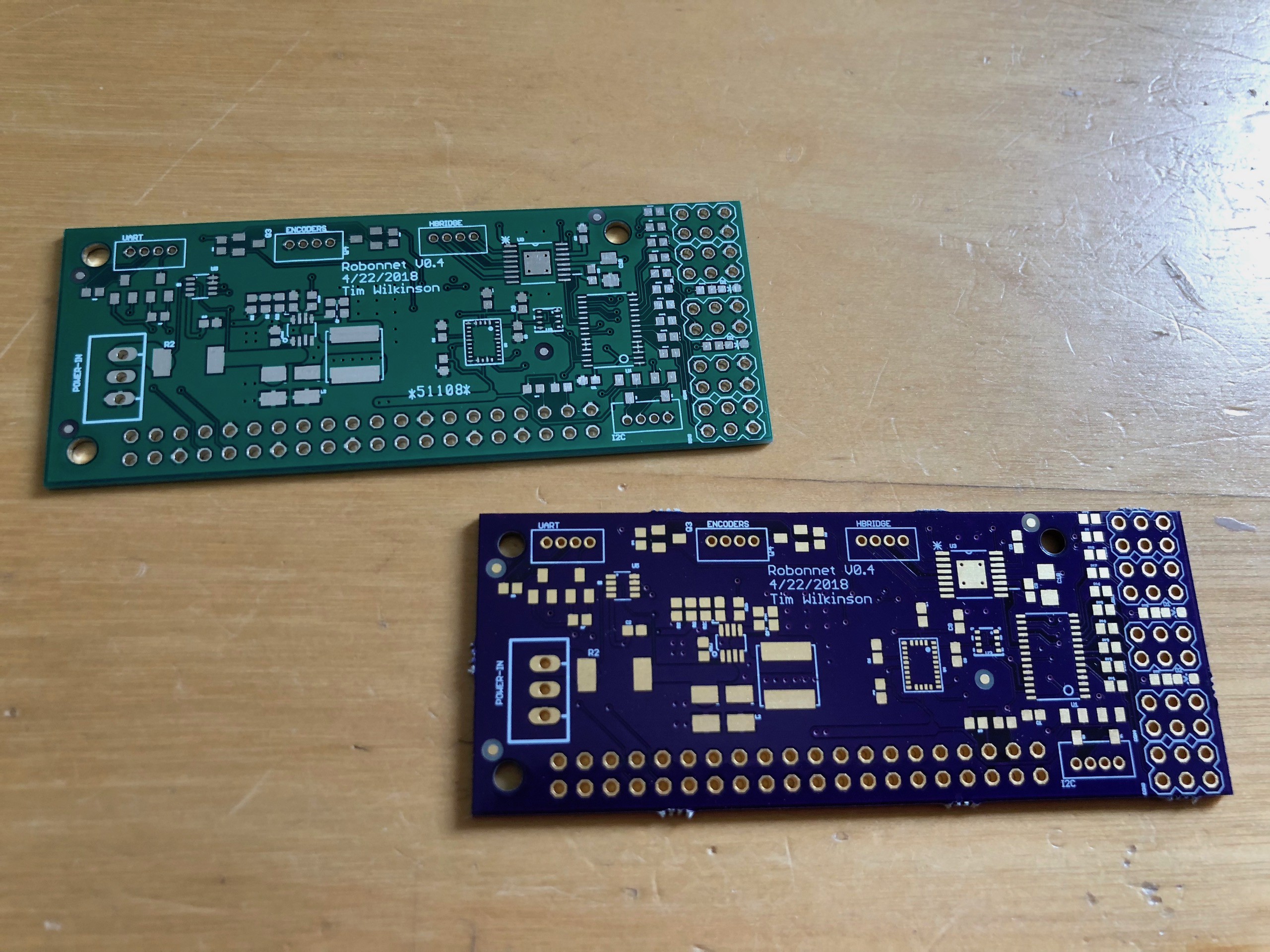
DirtyPCB v. OshPark
05/03/2018 at 21:51 • 12 commentsFor my most recent PCB order, I decided to have a race between DirtyPCB and OshPark to see which PCB delivery was fastest.
The two PCBs are now delivered and OshPark took 11 days while DirtyPCB took 9 days.
![]() ---------- more ----------
---------- more ----------But it's not an entirely apples-to-apples comparison. DirtyPCB cost me $41 for 30 (the minimum number at the lowest price point) and was 2 days quicker. OshPark's minimum was 3, was slightly slower, but at $18 was $23 cheaper!
So, which service to use depends on what you want, but I think OshPark might be cheaper for my next lot of prototyping where I only need a few test boards and a couple of days doesn't really matter.
-
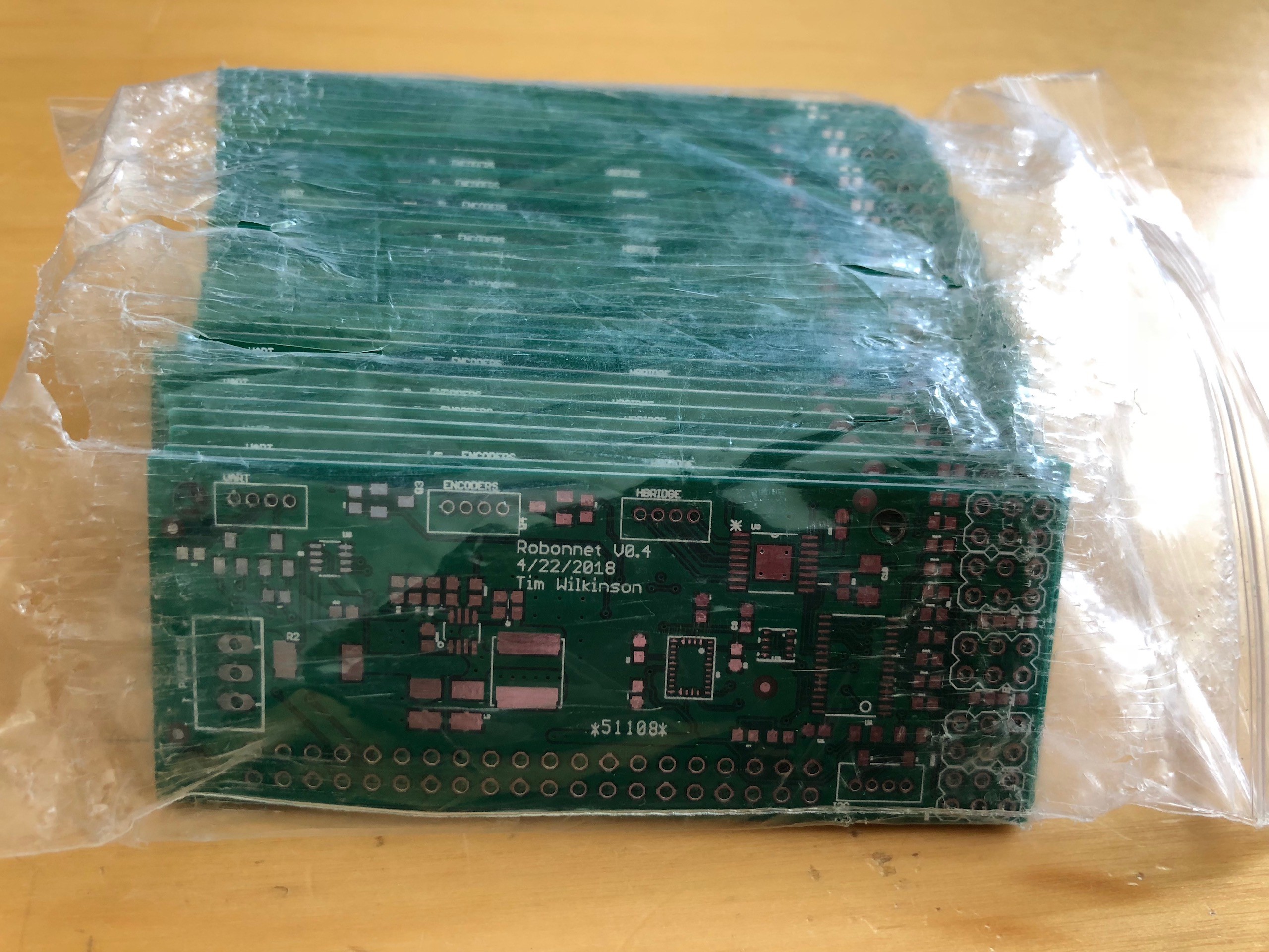
RoBonnet v0.4 - boards received
05/02/2018 at 05:40 • 0 commentsReceived the latest boards from DirtyPCB today. Hope to begin testing later this week.
![]()
-
RoBonnet v0.3
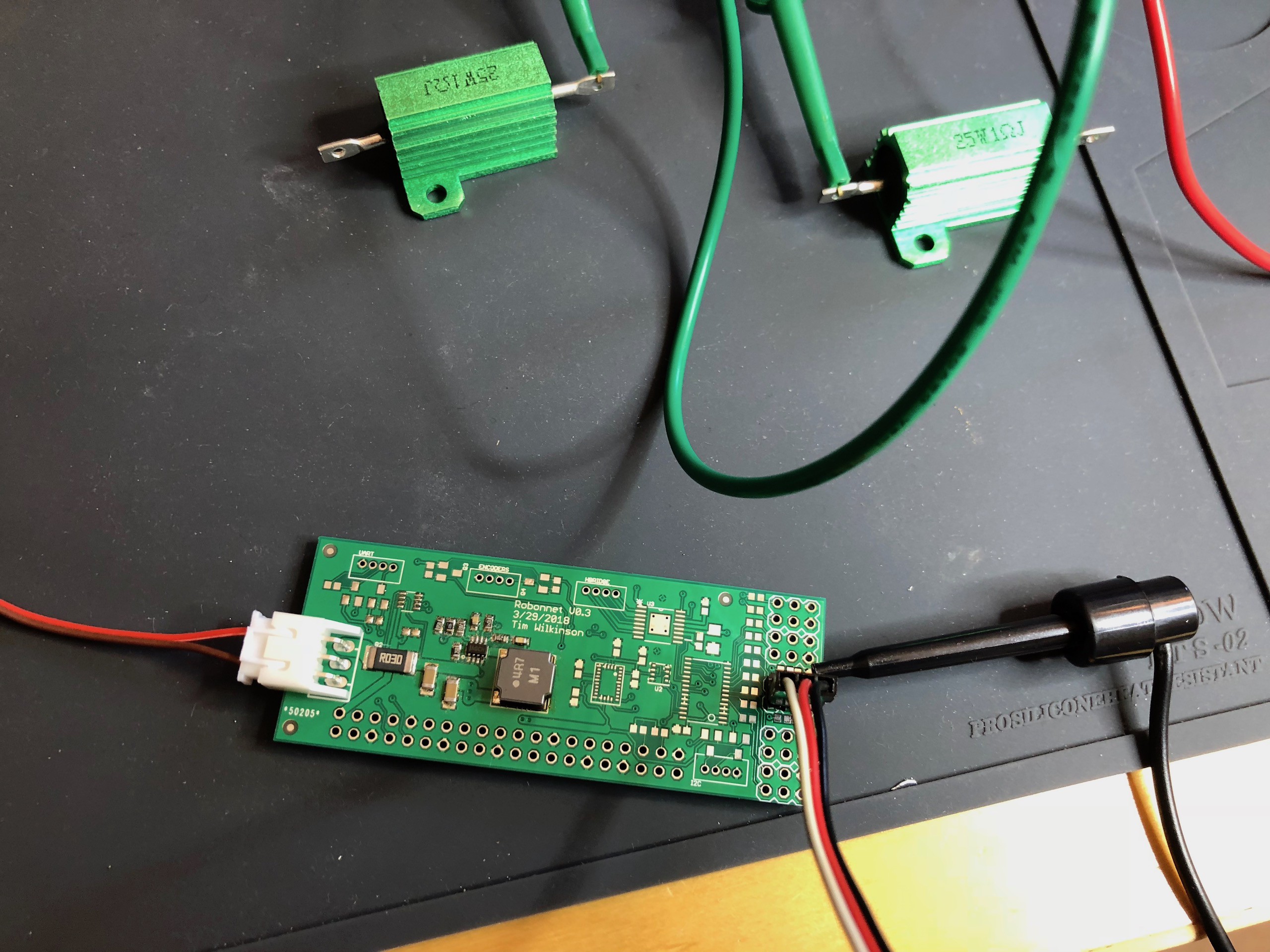
04/29/2018 at 17:38 • 0 commentsThe RoBonnet v0.3 is here. This is primarily a power test; a test to see if I'm capable of building a buck converter using the MP2315. Spoiler alert - no :-( At least, not quite.
![]() ---------- more ----------
---------- more ----------So the new board, shown above, is just populated with the basics necessary to test the buck converter: an MP2315, capacitors, random resistors to set the voltage level, and the main inductor. I carefully followed the data sheet instructions for part selection and layout because I don't understand these things so don't know what's important and what isn't.
When I initially power this up using my bench supply, it successfully regulated the range of input voltages I tried! Success? Turns out no. In the photo you see two 25W 1ohm resistor used to provide a simulated load of 2 ohms - so drawing 2.5 amps at 5V. As soon as I tried this, the regulated voltage dropped down to about 3V unless the input voltage was under 7.2V. To be honest I have no idea why, although it appears that the internal VCC regulator voltage also drops.
In an attempt to work out if I'd made a bad part selection, I scavenged various parts from some eBay MP2315 regulators that did work, but even when I swapped in those parts, my design failed in a similar way.
And so, I'm forced to assume it's my layout, and while I did try to stick with the data sheet layout, I definitely made some mistakes along the way regarding GND quality and some of the feedback paths.
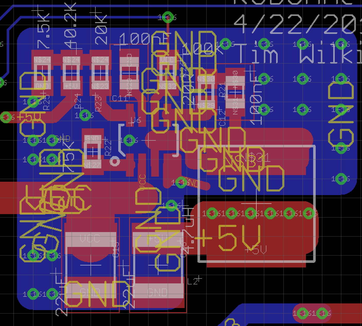
![]()
This, somewhat messy, screen capture above show the new layout, without the ground and power planes shown but with extra ground copper on both sides of the board. Let's see how this does.
-
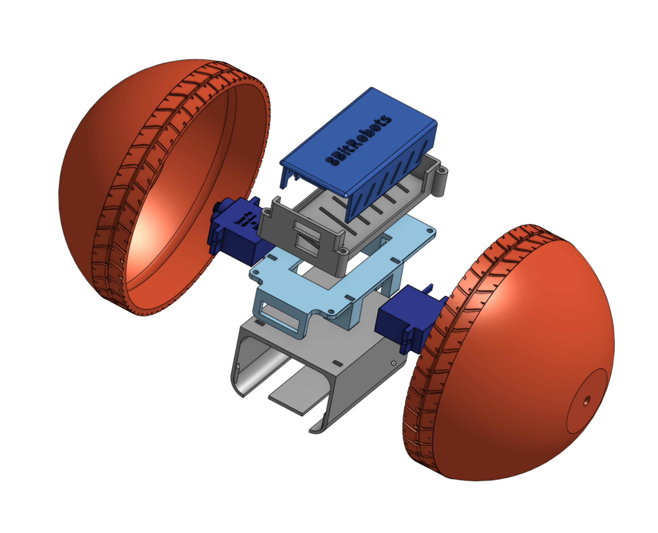
Anatomy of a robot ball
04/26/2018 at 16:16 • 0 commentsThe first 8BitRobots robot is a robot ball. The picture below shows the exploded design.
![]() ---------- more ----------
---------- more ----------The ball is constructed from several 3d printed parts and a few other bits:
- 3D Printed:
- 2 Hemispheres which form the ball case as well as acting as the wheels.
- The main frame to which all the other pieces are attached.
- Battery clip, which holds the battery holder.
- The 8BitRobots standard module enclosure.
- Extras:
- Two micro, continuous rotation servos to drive the wheels.
- Two M2 bolts to hold the wheels on.
- Some wire and a switch to wire the batteries to the module.
- 6 AA battery holder.
- A few zip ties to hold the pieces together.
- 3D Printed:
8BitRobots Module
A common hardware, software and 3D printed module to enable fun, educational robots anyone can print and program.