Torbjörn Lindholm
-
Possibly final update on the project
06/13/2021 at 14:55 • 0 commentsHello all, thank you so much for the love. It really does make me very happy to know that many people have enjoyed looking at my projects even a little bit. Thank you.
While I have... 3? 7? Uhh... Let's call it 6, 6 projects going on, I did not forget about this project. It's what has started me on the journey of fancy PCB designs, after all. It has a big sentimental value to me. So, this is possibly going to be the final update on this project.
I do plan to make a brand new MK3 version of this medallion. It'll have either more features or even more reduced features at the smallest possible form factor to facilitate more intricate designs. I haven't decided yet, and I'd like to get some input on the designs, features, or anything you'd like to see on the project.
Hope you all are staying safe. Take care, and see you again in the future! Happy hacking!
-
Rev.16 Update Log
09/10/2018 at 04:50 • 0 comments- Now MOSFETs have current-limiting resistors which can be used if you have MOSFETs with lower gate voltage (1.45V etc). By default the board aims for 2mA with voltage of 1.3V (R11 and R12 is 1K)
- If you have MOSFETs with 3.3V gate voltage, you can simply add 0R jumper resistor or bridge the pad with a wire.
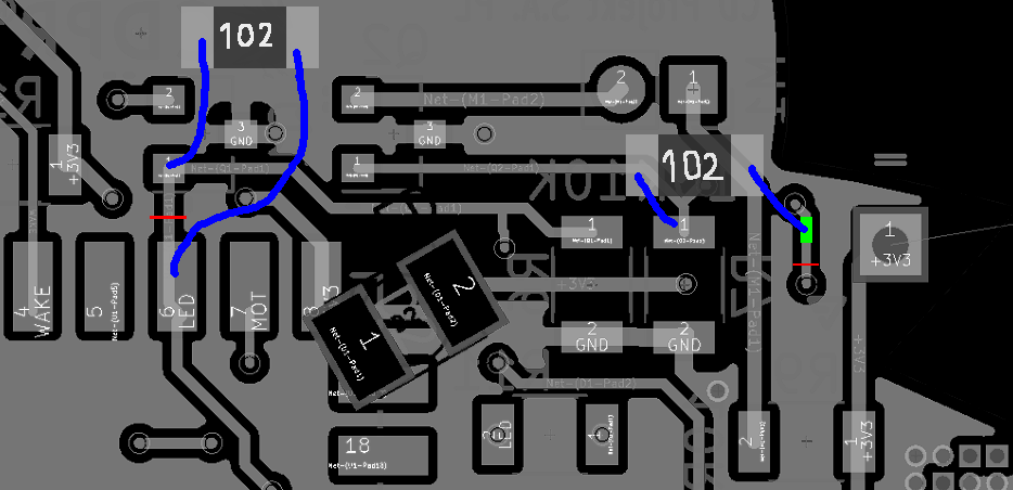
- If you happened to order the board before it was fixed, refer to this picture:
![]()
Cut the traces with red lines, scrape the part marked with green and wire the resistors up as shown here.
- Crazy value for pull-down resistors has been fixed. (R6 and R7 is now 10K)
- Crazy value for LED and motor current limiting resistors has been fixed. (R8 is 82R and R9 is 10R)
- Board layout has been tweaked slightly
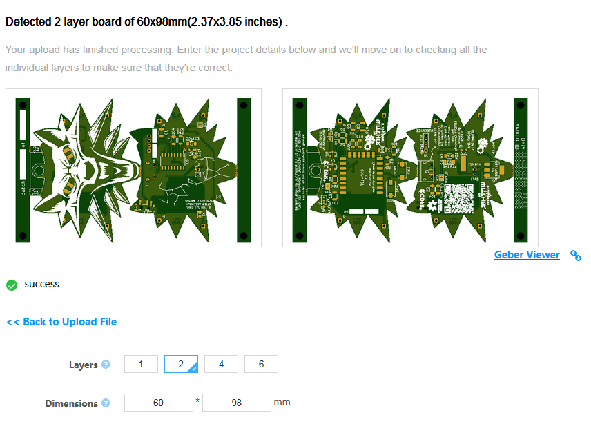
- Overall board size has been decreased for ease of manufacture
![]()
This project has been going on for a really long time and I hope all this was for something...
(Also I cannot finish the prototype boards because I did not receive all the parts)![]()
![]()
- Now MOSFETs have current-limiting resistors which can be used if you have MOSFETs with lower gate voltage (1.45V etc). By default the board aims for 2mA with voltage of 1.3V (R11 and R12 is 1K)
-
Rev.15 Update Log
09/03/2018 at 04:49 • 0 commentsOops. Mistakes were made!
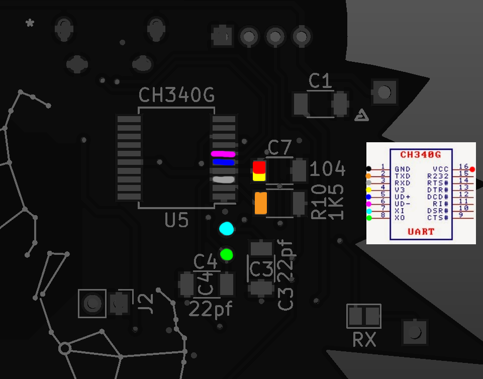
- CH340G footprint has been changed from SSOP to SOIC. This was a mistake carried over from using other USB-to-Serial converter chips. (Kids, sleep well. Else things like this will happen!)
- To fix the board if you happened to order the board before it was fixed, follow this diagram:
![]()
- To fix the board if you happened to order the board before it was fixed, follow this diagram:
- Regulator placement has been adjusted.
- Crazy track found near C3, C4 and Y1 has been removed.
- Board outline near the right ear of the backplate has been corrected to allow drills to pass through.
- Batch number, date and vendor ID sections has been added for future use.
- Use that for inventory tracking and other features.
- The board outline has been rounded a bit. Now it shouldn't try to dig into your flesh. If it does, sand or shave off the sharp points with a box cutter, dremel tool, jeweler's file or sandpaper.
That'll do for this update.
- CH340G footprint has been changed from SSOP to SOIC. This was a mistake carried over from using other USB-to-Serial converter chips. (Kids, sleep well. Else things like this will happen!)
-
Rev.14 Update Log
08/28/2018 at 06:25 • 0 commentsSmall but fatal errors were found on the board and has been fixed.
- 3.3V tracks had 0.2mm width. It has been corrected to 0.4mm.
- Motor tracks had 0.2mm width. It has been corrected to 0.4mm.
- LED tracks had 0.2mm width. It has been corrected to 0.3mm.
- Copper islands that was not connected has been reconnected.
- Incorrect footprint associations for jumpers were fixed yet again.
-
Rev.13 Update Log
08/26/2018 at 07:36 • 0 commentsPretty minor pre-flight check misses were found and fixed:
- Crazy track found near motor MOSFET was found and removed.
- Copper fill has been refreshed.
- The component list has been updated.
- Wrong component value for current-limiting resistor has been fixed.
- Affected components:
- R6 and R7, 47R and 10R respectively
- To reduce the brightness, increase the value of R6 to 100R
- The component list has been updated to reflect on the changes.
- Speck of incorrectly placed track near the edge of the board has been removed.
- A wrong value was used for R6. It has been fixed. (45R -> 82R) If that value were to be used, the current would be 28mA instead of desired 15mA.
- The single SIP switch has been changed to more readily accessible MSK-12C02 clone switch. (Credits: mzst)
- The position of the switch has been moved to more accessible area.
- A little bit of pizzazz was added.
- The board layout has been changed.
- The snake-through track has been rerouted.
- The little break-off tabs are now thicker to prevent it from falling off during manufacturing.
- Board version has been updated.
- Now the archive also includes firmware.
- Firmware issue (watchdog timer issue) has been fixed, perhaps by an overkill solution.
JLCPCB has contacted me about this board and I'm gonna have it manufactured. Time to go shopping for the components!
Update: Shopping is done. Now we wait...
-
Rev.12 Update Log
08/21/2018 at 17:32 • 0 commentsSometimes you just have to look back and see what has become of this project.
Oh wait, no. I was joking. Just an another update!
- Completely overhauled the circuit
- Removed charging circuit (power source changed - Li-Ion Booster pack required)
- Attempts at panelizing PCB were done
- Support pins are now data transmission lines too
- Three-layer designs? Maybe?
- Added on-board USB-2-UART adapter
- Added ATTiny1634 blinkenlights
- Removed blinkenlights (Not enough PCB space, schematic can be found in 8seg_blinkenlights.sch)
- Revamped UART adapter design (Taken from https://github.com/NiceCircuits/modules_from_china)
- Removed redundant parts
- Fixed incorrect jumper footprint
- Minimized component count
- Update logs updated to update on the updates and to improve on wordings of updates, driving the point of updates to home and to put as many of the word "updates" in one sentence
- Mouse bites added
- Electrical mistakes fixed
- Redone daughter board because it was mirrored
- Euuuurgh
- Imported the features from original daughter board back to this PCB
- Added OSHW logo
- [pain noises]
- Electrical wiring tested somewhat, may or may not require cut tracks to make it work
- Panelizing attempts were made
- Uhhhhhhhh
- This update log is getting very long but the Read More tag won't work for some reason so this will do
To-do:
- Figure out a way to mount the battery pack
- Figure out what battery to use, since AA cells or 18650 is out of question... Perhaps few of those lithium AA batteries could work because their nominal voltage is higher
- Oh wait, what about the 9V battery
- Turns out linear regulators are really bad at being efficient
- Hmmmmmm
- Uhhhhh
- Shoot
- Find an engineer, my head is getting overloaded
-
Yikes!
08/19/2018 at 17:34 • 0 commentsA fatal flaw has been identified on the power circuit and it's being fixed now. Also, now the daughter board will actually do something if you decide to populate it!
-
Oops!
08/18/2018 at 15:48 • 0 commentsTurns out the format for the drill file was incorrect and the pre-made Gerber files are missing the component references, which is required. Please don't use the pre-generated files!
-
Revision 11 Update Log
08/18/2018 at 04:26 • 0 commentsMinor compatibility fixes here:
- Board outline has been redone properly to ensure 100% compatibility between other programs, no more ugly null component hacks here.
- Ornamental backplate has been redone too to ensure compatibility between other programs. Please note that all footprints on the board is only for show and you are not supposed to solder stuff onto it, but if you really want, you can do that, I suppose. It won't do anything, though.
- Spacer pins are added. Length is about 7.5mm and the black plastic piece must go inside the circuit board sandwich and soldered on both sides to add rigidity. Flush-cutting or dome of solder is required to prevent lacerations and damages to clothing and other delicate objects (such as human flesh). Silver or lead-free solder recommended to prevent leeching of lead metal.
- Logo position has been moved and resized.
- Typos has been fixed.
Some warnings for people with sensitive skin:
- Fiberglass board pieces near the mouse-bites or V-cuts (snap-off tab) can be sharp and strands may be irritating to skin. Sand and seal off the mouse-bites after it has been snapped off (if applicable).
- Lead poisoning may occur if leaded solder is used to solder places where water, humidity, salt or sweat can come into contact (such as outside perimeter of the circuit). If you feel nauseated or dizzy, remove the board immediately from the body and seek medical attention.
- Some board manufacturing processes may use non-lead-free processes and may have residual toxic chemicals. Wash each circuit board before wearing. (Isopropyl alcohol followed by dish soap will do, do this before soldering)
-
Melancholy
07/30/2018 at 13:41 • 0 commentsCurrently looking for some engineers who can verify that this board is at least fit for production. I was unable to source the QA tester locally and one mistake could cost me a lot, due to it being expensive to manufacture.
Also, should I change the ESP8266 to ESP32?
Witcher Wi-Fi Medallion MK2
Didn't like the metal necklace, so PCB art was the way to go.