WARNING: Don't try this at home.
iMac G3 Casemod
Building a gaming pc in an old iMac G3 case
Building a gaming pc in an old iMac G3 case
To make the experience fit your profile, pick a username and tell us what interests you.
We found and based on your interests.
WARNING: Don't try this at home.
Since the last log, I finished this build. It took me 4 days total to get everything right and I didn't keep good documentation on anything, including the 3d files, so I'm not entirely sure they are the best versions... but I'll try and fix that later.
I'm just going to go through building this damned thing step by step, here it goes:
Next up: Drilling and sawing holes in the metal baseplate to route cables. This was easier than I expected, just took some elbow grease but apparently aluminum is quite soft.
Be sure to use a jigsaw or handsaw and not a dremel though, because as it turns out, aluminum dust is toxic and might explode!
After that I made some cables. I connected the old iMac's power button and power led to some female headers, easy enough. I didn't want to try and figure out what all the circuitry on the headphone jacks was about, so I didn't even try to hook that up. (Although I think it's just a sense circuit, so you might be able to use it with an HD audio connector)
The speakers also needed a cable. I tried to plug them in to the HD audio connector on the motherboard and that really wasn't loud enough, so I used a PAM8304 breakout board I got on aliexpress and powered that using the D_LED header on my motherboard.
Last place to drill some holes was on the bottom of the plastic chassis for the GPU. I chose a blower style GPU so it would have it's own separate airflow from bottom to back. I used the same stencil for this as for the top fan.
I think that was most of the chassis work (apart from some holes you need to drill...) so now, with all the 3d printed parts, I think we're ready to assemble.
First up is the IO bracket. I glued all the cables in place with some transparent epoxy. Due to bad design, the USB-C connector on the top could only go in after this thing was already mounted to the metal baseplate and to make things worse, one of the two screws holding that in place was also in the way... It did work out in the end though, just needed to scrape some plastic off the connector and convince it to stay in place for long enough. You should end up with something like this.
With that out of the way (more like in the way) It's time to mount the GPU. I tried a lot of versions of my models on this and in the end one of them worked out, but it sure wasn't pretty and even less easy to install.
With the GPU in place this might be the time to finish everything on the bottom. Add the speakers and bottom chassis connectors now. This may be a little hard because they're all very close together, but it should work out fine.
On to the top: cable manage all those cables from the IO shield underneath the motherboard mount and zip-tie that in place.
Now is the time to add your HDD (or not, I'd recommend not to, you'll see why later on...)
And then screw in your motherboard. ...
I'm in the middle of my exams at uni right now and all I can think about is this computer, so I went home and worked on that instead of studying... bad decision...
However (!) after waisting just a single day I did fix the entire bezel :D
So here's a step by step:
Once you've done this for all 4 parts, your bezel should be complete. Try if your LCD fits and bask in the feeling that this project is almost over.
I think it's beautiful, but this might be a 'my baby' kind of situation.
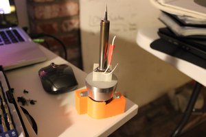
So I bought a 3D pen to try and weld the 4 bezel parts together.
This is the test run on some prototype prints. I'm amazed by how easy this was and how sturdy the result actually is.
Final result (bezel only) will be ready in a week :D
Some of the extension cables for the IO shield arrived, so I'm trying to finish the layout and print a final version.
A few of these cables have screw holes and extra protection that's going to be in the way, so I'm removing that with a box cutter.
I tried some test prints with the transparent PETG filament I bought some time ago and got pretty good transparency, but the geometry of the IO shield doesn't seem to work as well. Might need to work on that if I really want it to be more transparent.
All in all I think it's coming along quite nicely.
I'll be doing a few things next:
- Printing a final IO shield (more transparent)
- Using epoxy to glue the cables to the IO shield
- Printing the front bezel in a final plastic and using a 3d pen to weld the (glued) parts together
After all that is done, I can focus on mounting the internals.
My PSU hasn't arrived yet, but I plan to put it underneath the metal baseplate of this iMac.
Problem: There isn't really enough space in terms of height.
Solution: Permanently glue the RAM access flap in place and add some holes for extra ventilation.
The holes are spaced 7mm apart and are about 4mm diameter. Mine are certainly not perfect, but they're also not that bad.
*** Update this with pictures of permanently glued plate ***
I also wanted to remove some of the standoffs that are on the metal plate, because they might be in the way of my motherboard . I read online on this guy's mod of the G3 that you can just wiggle them off. After some vigorous wiggling and smashing with a hammer I got the hang of it.
Just be careful with your hammer, don't go too crazy or you might break something...
I also finally finished the mounting plate for the IO shield. Took my a couple tries, but got there eventually.
After printing about 7 failed attempts, I got tired of wasting plastic and remembered I had a 3D scan laying around. This helped A LOT!
The model now fits and I'm finishing it off with a power button mount and some brackets for the LCD. Fingers crossed this whole contraption is strong enough to support the weight of my LCD.
In the meantime I've also been working on the IO shield. Had the same problem, this iMacs curves are just too pretty to be modeled by a novice like me. Made a scan here too and now it fits perfectly. (no really, almost better than the original)
I'll check back in when the model is finished and I can start glueing this thing together.
After paying reddit user u/dahmze1 to make me a model of the inner bezel, I tried to print it. Sadly it didn't fit at all, so I've started modeling it from scratch again.
Lucky for me my modeling skills have improved significantly and with a model to start off from I had a little better success.
After tuning in my printer, I printed the first attempt. Alas, didn't fit. But it's getting close...
Clearly some tweaking is still needed.
Create an account to leave a comment. Already have an account? Log In.
Ciao, complimenti per questo progetto è davvero interessante. Io invece ti scrivo per chiederti alcune delucidazioni, visto che ho preso da poco un vecchio imac g3 identico al tuo come case (ovvero versione Indigo). Essendomi però arrivato con l'inner blaze completamente distrutto, volevo sapere se tramite i tuoi disegni e con l'aiuto di una stampante 3d riuscivo a ricrearne uno identico al vecchio, così che io possa sostituirlo al mio. Resto in attesa di un tuo gentile riscontro e semmai in delucidazioni utili al mio progetto. Grazie e buona giornata.
Hi, I m currently working on the same kind of project. The motherboard and all the other component have been built in. Now I m wondering how you managed to get the old power button and led connected to the motherboard. How would I make my own 4 pin connector to connect to the motherboard and what would I need in order to pull it off? Thank you in advance. Loved the project post.
This is a great project! I've actually done something similar with an eMac and I'm in the middle
of doing something similar with an iMac G3. The difference is that I want to use the original
CRT. So far it's working but I need a replacement inner bezel. I can't believe you made one!
Will your design hold the original CRT? If so, can you share the design files? or the STL files
so I can print it myself? Great job!
Take a look at what I've done and doing.
eMac with retropie
iMac G3 with raspian
The design files and stls can be found on my github. Link is in the description of the project (https://github.com/Diepzeevogel/iMac-G3-replacement-parts).
I don't know about the original CRT, that's not what I created these for, but I'm sure you could edit them to fit.
Good luck with your project!
Hey there !
I'm a French engineering student, and it looks like we had roughly the same idea at the same time - except you actually had money to make it real (and a 3D printer).
I think that using 3D printed parts instead of the original ones but modded was a real good idea - i wish my LCD panel was thin enough to put it without removing the case from the screen.
Also, i tend to think that using a blower GPU may have been what caused the heating issues, since that case is very badly ventilated, and you didn't put an extrude fan in the front of the case. I'm going to be trying with a regularly mounted dual fan 1060 and tell you how bad the heating is when i get there.
I'd like to know a few things :
- did you use a drill for the holes in the rounded thingy under the handle? Any recommendation on how not to break the acrylic?
- how exactly did you attach that ITX motherboard to the original tray? and most importantly how did you avoid contact between the motherboard and the tray?
- do you still have the links where you bought the IO extensions? I've been looking for some cheap ones for a long time...
Thanks again, your work was pretty darn good.
Hi!
Thanks for the kind words, I appreciate it a lot :)
I'm curious to find out if your version works out better!
To answer your questions:
- Yes, I used a drill/screw machine. Just be gentle and let the drill do its work. Some holes had some light cracks, but overall it was quite easy.
- I have a 3d printed part that attaches the motherboard to the tray. It leaves some space for cables and attaches with zip ties through the holes in the metal plate.
- I don't have any links, but I bought them all on AliExpress, should be easy enough to find. Just make sure you look at hdmi versions and stuff, you don't want to fuck yourself over with those cheap cables.
Alrighty! Six months have passed and i'm not dead.
Thanks again for your answers, they will definitely help me a lot.
Just received the motherboard (FINALLY), and it seems i'll have to make my own mobo standoffs and GPU holders, and all that without a 3D printer! Gonna be one hell of a ride...
Become a member to follow this project and never miss any updates
By using our website and services, you expressly agree to the placement of our performance, functionality, and advertising cookies. Learn More


 Hunter Scott
 Kenneth Zaborny
 dbtayl
Which LCD screen did you end up using for the project?