Resources
Datasheet: http://www.vintagecomputer.net/fjkraan/comp/qx10/doc/nec7220.pdf
This is best used for designing a circuit with the uPD7220 and for understanding how to initialize and draw with it.
Programming Manual? : http://www.vintagecomputer.net/fjkraan/comp/qx10/doc/nec7220.pdf
This will explain how to send commands and generally how the CPU to uPD7220 interface works.
My Z80 code: https://github.com/NuclearManD/z80-code/blob/master/G00nOS/upd7220.z80
This is the graphics driver I am writing for my Z80 computer. It's good example code, but it currently has numerous limitations, so look at the arduino sketch I uploaded to this project as well.
Why?
I want a graphics card for my Z80 computer so it can operate completely independently, as in, without a serial monitor.
I don't want to use a propeller chip or other powerful microcontroller because those chips don't go with the rest of my Z80 computer. Besides, something about this design just feels really... pure, I suppose. Clean.
NOTE: The information provided in this details section is very condensed. There is much, much more to be understood. I recommend STUDYING the documents I linked and uploaded. The following information is just a brief overview.
How does the hardware work?
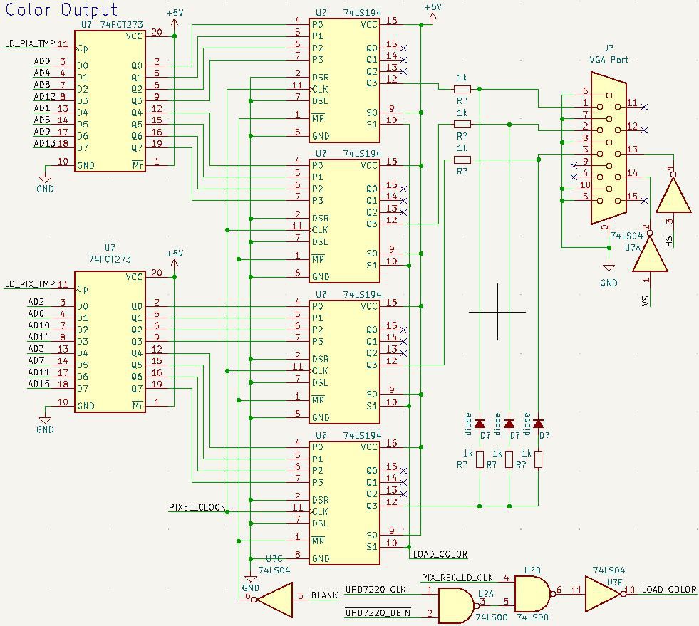
The uPD7220 generates VSYNC, HSYNC, and BLANK signals. It generates a few other signals for the memory interface, but these must be interpreted. The uPD7220 address and data lines share a bus, so the address has to be latched. Also, to write to memory, there are special cycles which require external hardware to generate a write enable.
There are two clocks. The pixel clock, which is currently 8Mhz, is used to output pixels. The uPD7220 takes lower frequencies, so the pixel clock is halved to make the 2xWCLK clock, which is sent to the uPD7220.
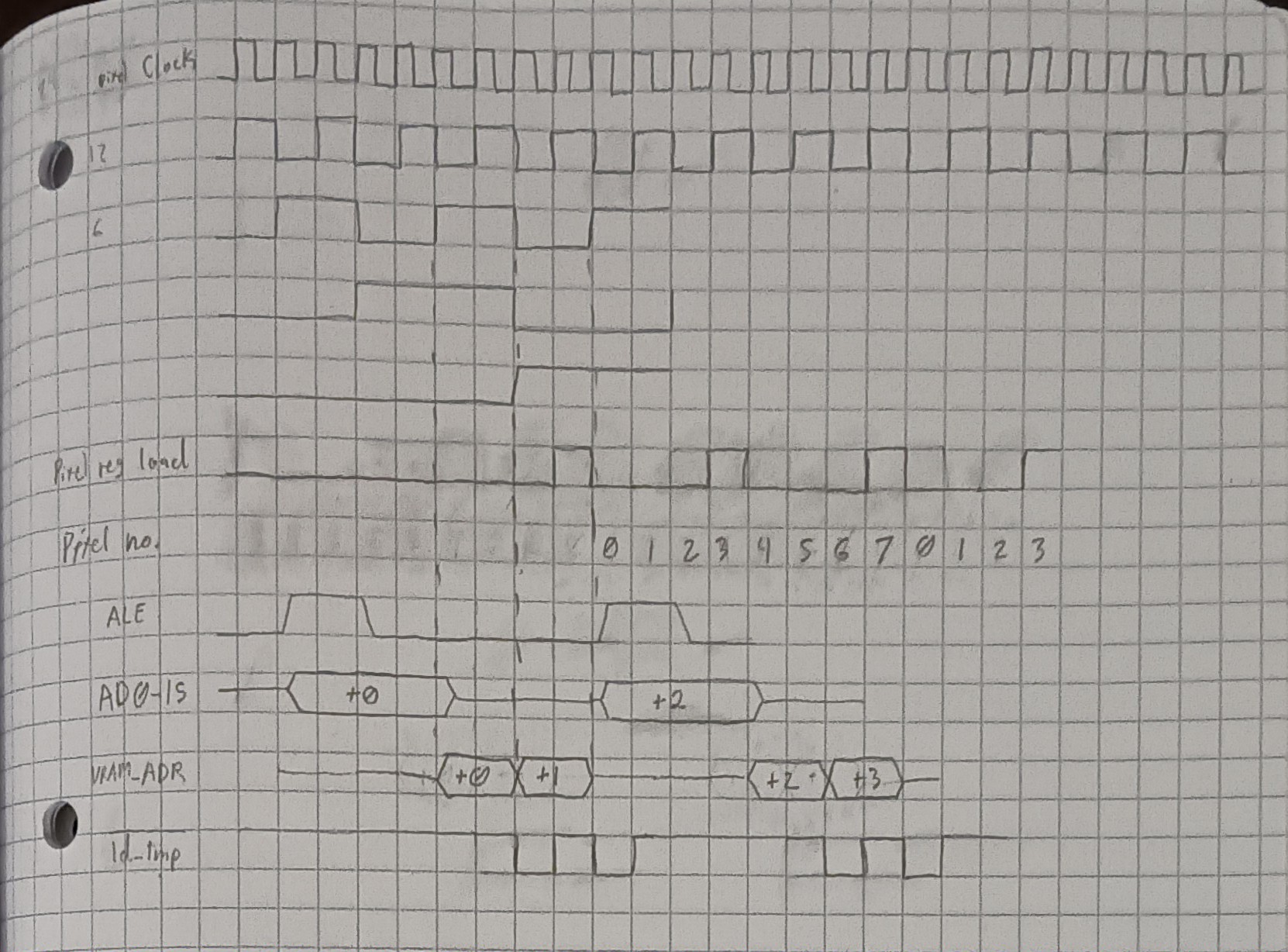
The uPD7220 reads the pixel data onto the data bus, where it is latched every fourth pixel clock rising edge. The shift registers output pixel data while the uPD7220 prepares for the next set of pixels.
The port which goes to the system microprocessor is directly connected to the uPD7220, except for two OR gates which generate the WE and RD signals.
How does the software work?
There are two ports that can be written/read on the uPD7220:
| READ | WRITE | |
| 0 | Status register | Parameter load |
| 1 | Data to CPU FIFO | Command load |
Before each write, the status register FIFO full flag must be checked first. If the FIFO is full, then a write will create undefined behaviour.
The uPD7220 must be initialized properly first. If it is not initiallized right, then random commands will crash it when it is least expected. These commands all must be used in initialization:
0x00 : reset (followed by graphics parameters)
0x47 : pitch (aka tell the GDC the number of horizontal words there are per line)
0x70 : set up PRAM so drawing operations work
0x4B : CCHAR : set up character parameters.
0x46 : set the zoom. Otherwise zoom may be random.
0x6B : start the display! YEET!
 Dylan Brophy
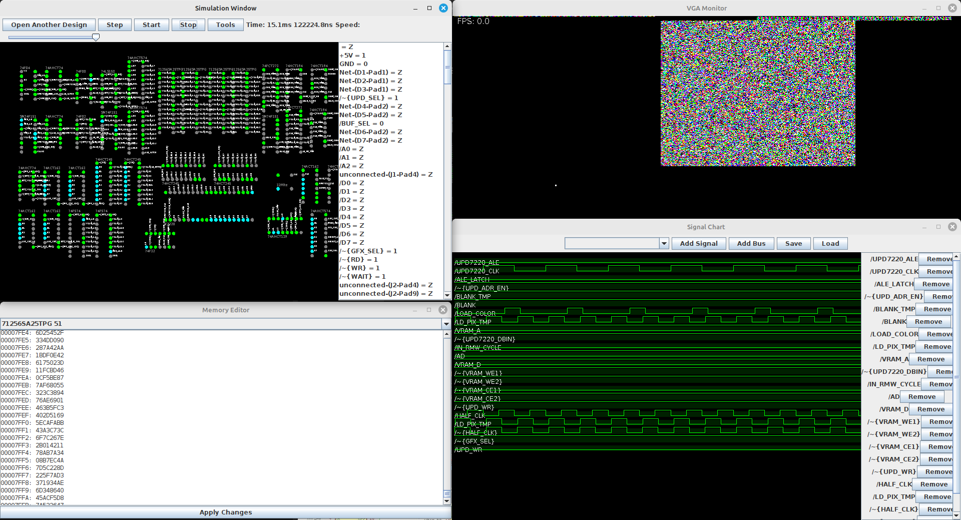 The simulator has some handy features for graphics devices particularly, for example, a VGA display simulator. In the picture, there is a white dot on the VGA display - that is the position of the electron beam at this particular tick. The sim was definitely engineered to my particular use case. Well, I'm pleased with it and hope to use it in projects in the future. Now I can know if a board will work before I order it.
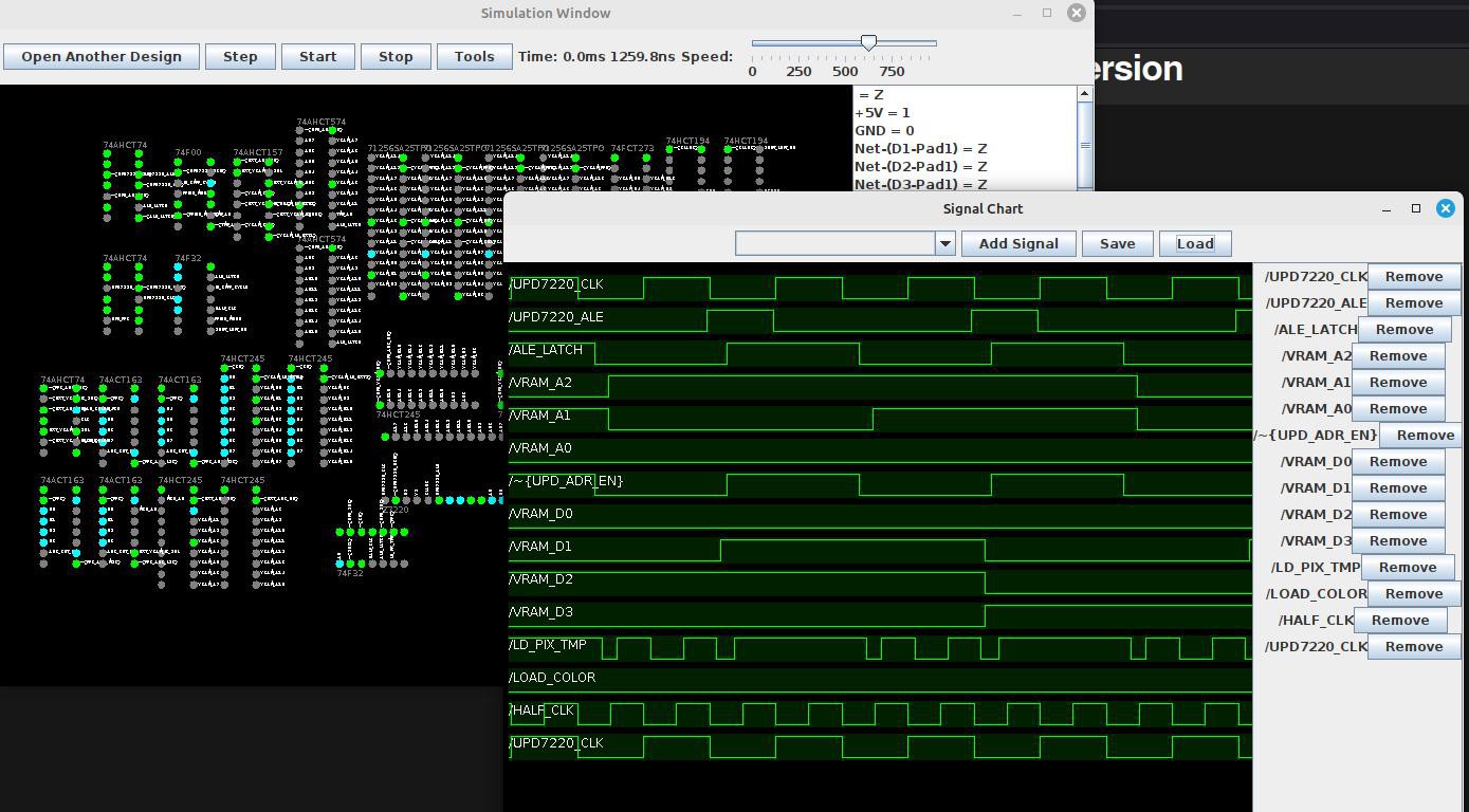 It is VERY alpha, and the library of components is incredibly limited. It has bugs and the UI can crash sometimes. That being said, the simulation itself does not seem to have any problems. It does just one thing extremely well: it simulates the card I'm working on. With some relatively small upgrades it could probably be used to simulate a wide variety of digital circuits.
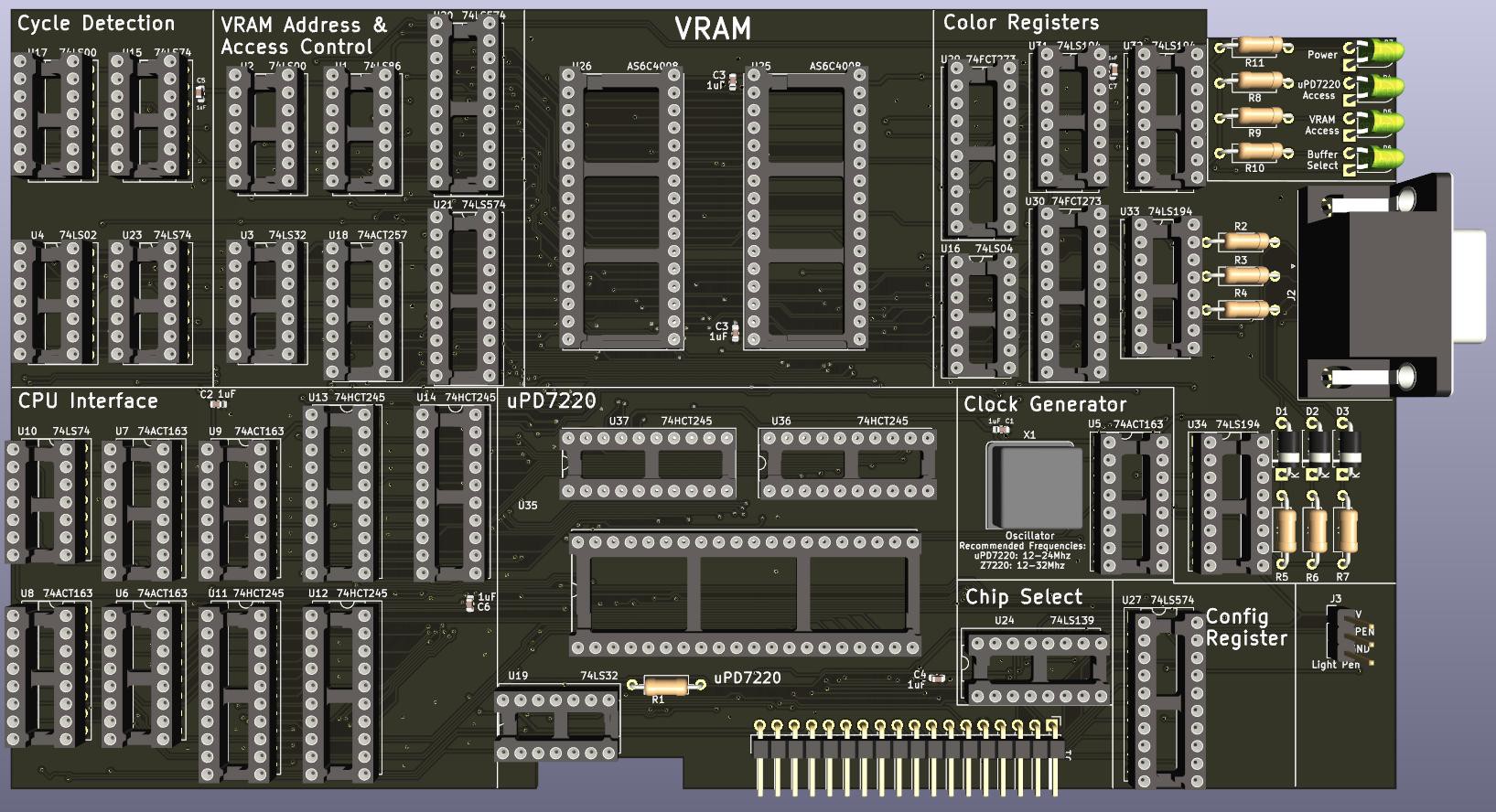 I tried to make the parts of the circuit clearly visible on the board. I also added LEDs, which I typically forget when designing a board. Every board needs blinking lights. Well, I think this board has turned out nicely, at least in the 3D render; it has the clean look I wanted.
 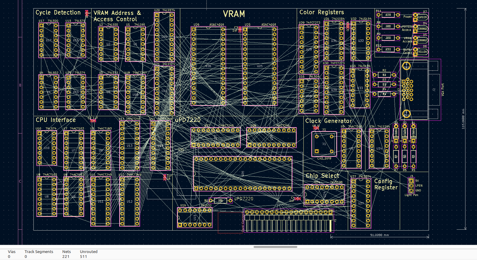 The board now:
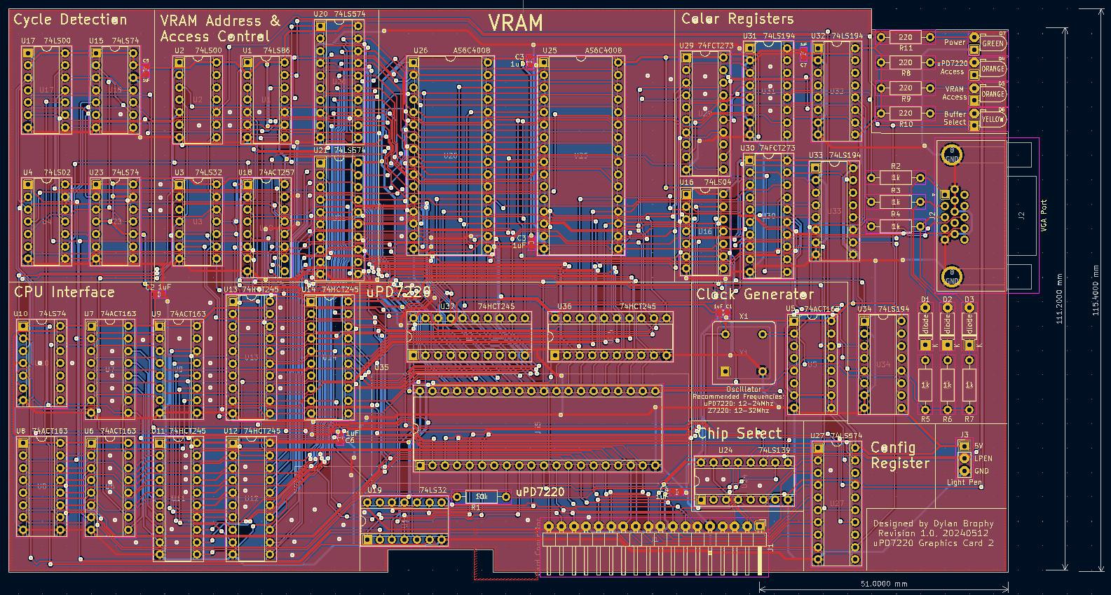 This board was a lot easier to route than I expected. Anyway, expect an update in maybe 10 days when I actually assemble it.
 I may add more decoupling capacitors still, but that isn't a real design change. The capacitors are the only SMD components I'm using.
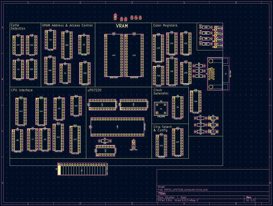 I think I'll also need to make some minor adjustments to the circuit design so the routing is easier, but these are not really functional changes - things like changing the bit order on registers, or rearranging the allocation of gates from chips.
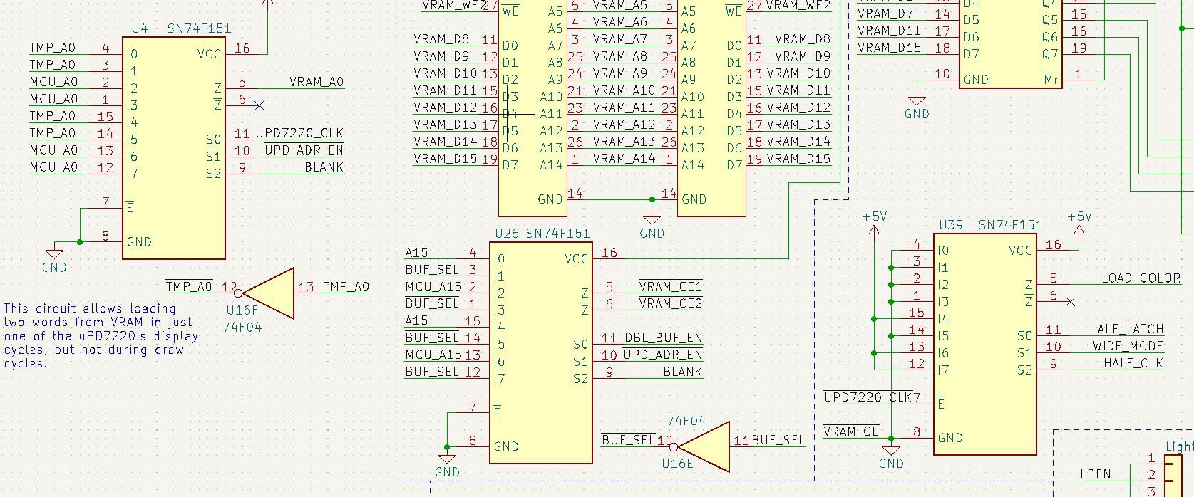
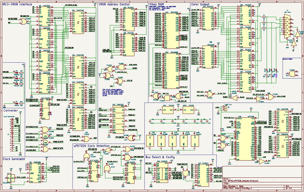
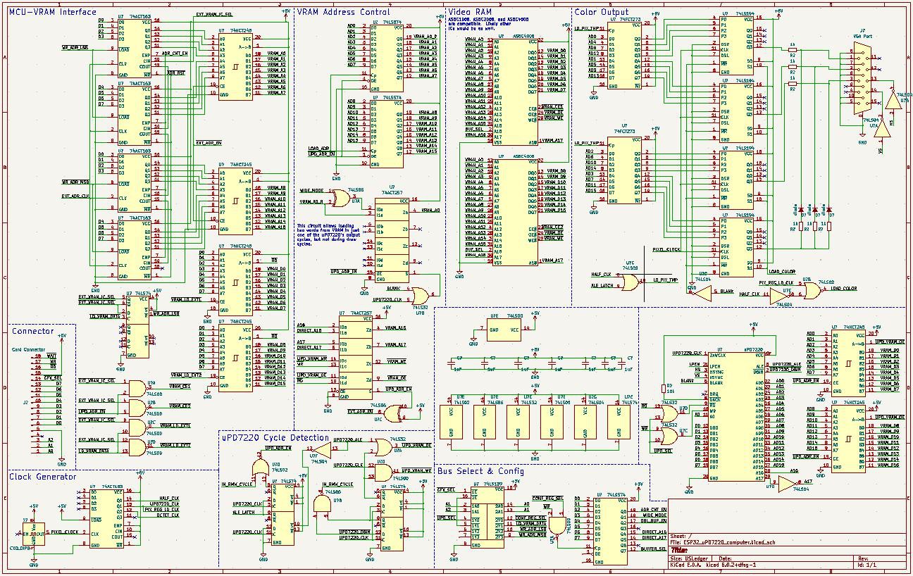 This schematic is way better organized, and hopefully it will still make sense to me 5 years from now. I've added a ton of features since the last board revision, namely:
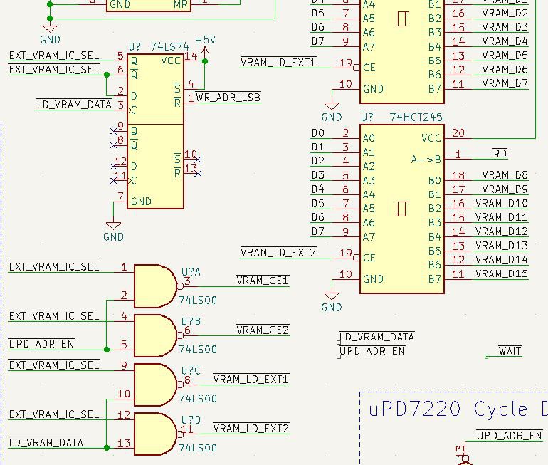 Some of this logic is wrong I think, namely I'm suspicious of the two bottom NAND gates, and I need to add logic for the WAIT line, but this image should give some idea of what the logic is supposed to do. After the main processor writes the lower address byte, the byte-select for the VRAM is reset to zero. Then the processor can write a single byte to the VRAM, which automatically switches the selected byte so the processor can write the other byte. This is done because the VRAM has a 16-bit bus and the processor has an 8-bit bus. Depending on weather the address counting is enabled, the address registers will actually count up to the next word in VRAM, so that the processor can send up to 128KiB of uninterrupted data to VRAM. This is done in-between accesses done by the uPD7220, as the bus is shared, and the uPD7220 gets priority.
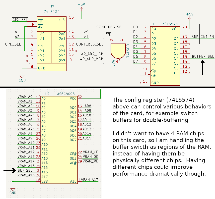
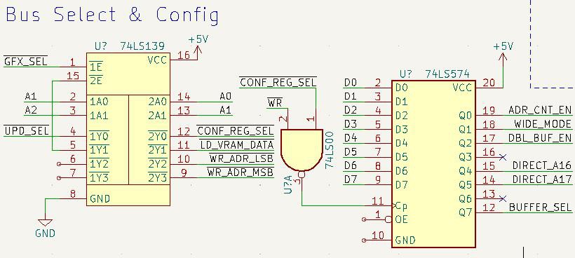 I realize now, looking at this, that I may be able to remove a latch by using A0 for byte select instead of automatically selecting it. Something to think about. Anyway, in the image above you can see that the config register can enable/disable the wide mode logic, control automatic address count, enable or disable double-buffering, to swap buffers, and set A16/A17 for direct VRAM access. The double-buffer enable will make the uPD7220 and processor write to the opposite buffer as the one being displayed, but the buffer still must be manually swapped by the processor.
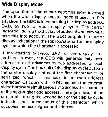
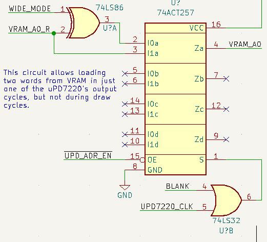
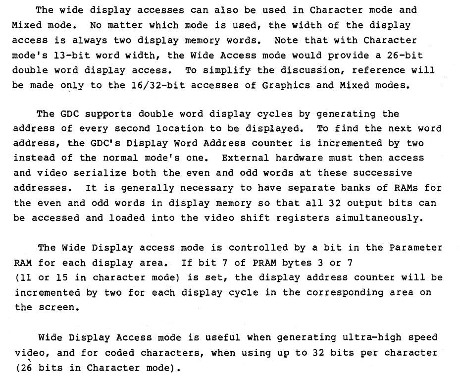 As it turns out, I don't think I can get it to add 4 instead of just adding two as described above; this limits my maximum clock speed to 24Mhz (32Mhz on the faster Z7220), so the maximum resolution would be limited by this. On the other hand, the uPD7220 supports interlacing, so I might be able to push out a higher resolution that way. Without interlacing under this config, I can't even get to 640x480, but with interlacing I can get at least to 720x480. I'll have to play with the settings.
 As a bonus, I'm including a timing diagram from the datasheet so it is easier to find later:
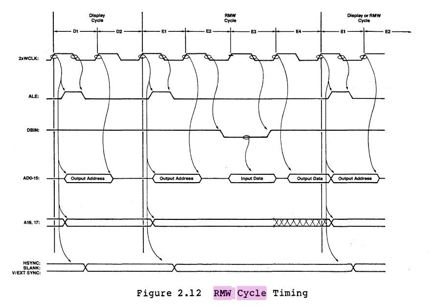 This image details the cycles of various uPD7220 memory accesses, and is super useful for designing the memory control logic.
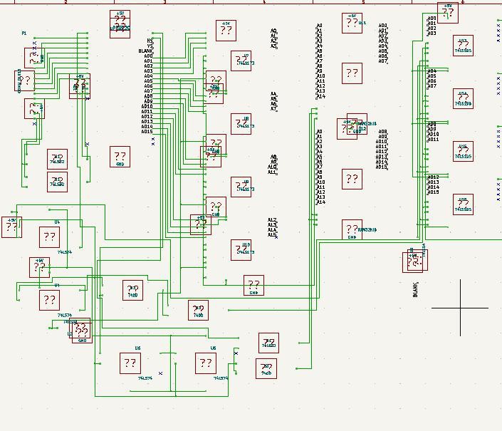
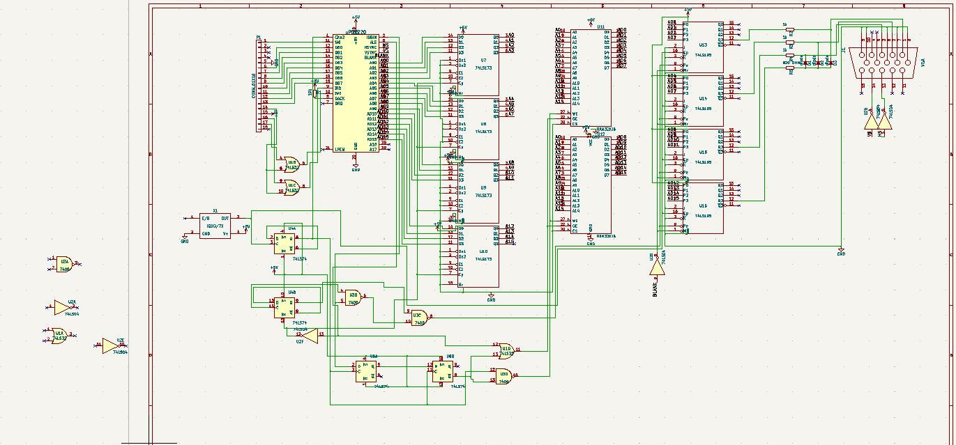
 I'm not a huge fan of the old board's low resolution. I want at least 640x480, if not higher. Adding more memory for this is quite easy, and in the new schematic this is already handled - the hard part is getting the clock speeds high enough. The uPD7220 can clock at 6Mhz, and the current card gets this by dividing it out of a 12Mhz clock. With a Z7220 the clock is a bit higher, 8Mhz and 16Mhz respectively, but this is nowhere near the pixel bandwidth needed for higher resolutions. My solution to this will be to divide the uPD7220's clock one or two times so we can get 24Mhz or 48Mhz pixel clocks on a uPD7220. That should allow us to get way better resolutions:
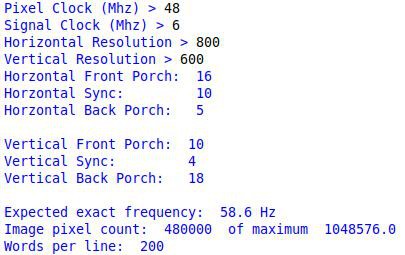
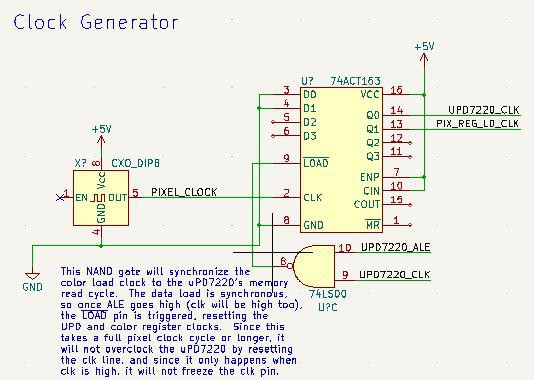 Anyway, I have more stuff to figure out with the board. If any of you have good ideas on the clocks and loading twice the pixels from RAM, let me know :)
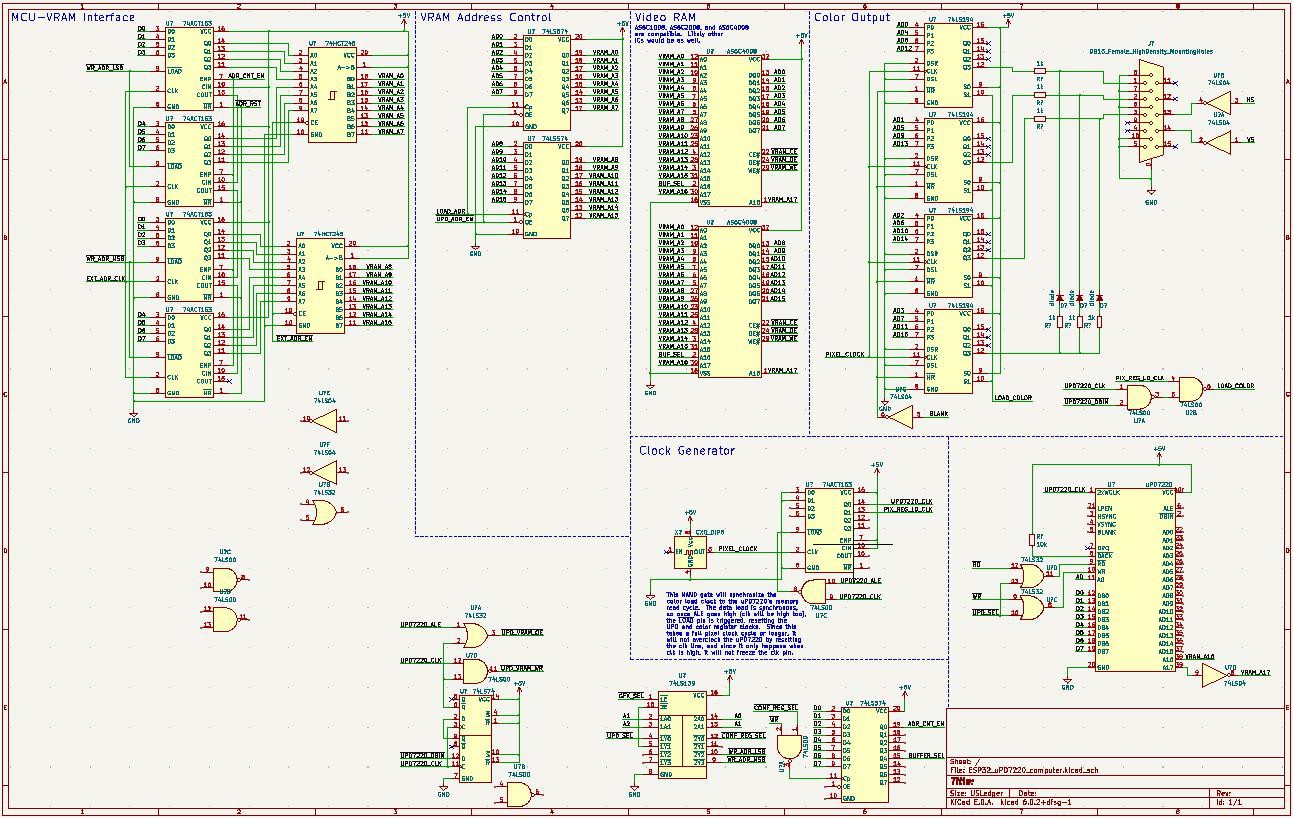 Hopefully my schematics are prettier and more useful this time; I think they will...


 Dave Collins
 Anders Nielsen
 Keith
Keith
Hello
With the help of members of forum.system.config I created a graphics card based on the NEC µPD72020 processor.
I managed to create a basic driver by using existing routines on the MicroBox II, in particular the classic functions (Point, line, arc, rectangle...)
On the other hand, for several weeks I have been trying in vain to implement drawing commands using fill patterns...
I stumble over a detail that escapes me!
The rather efficient NEC 7220 processor has been used on many
machines, there must be a person on the planet who owns
some examples of code implementing these filling functions.
Thanks you for your help
Michel Guyot