Close
0%
0%

Irreproducible clock

A clock you won't have a display for

Similar projects worth following
Just an excuse to use something from my junk^Wspares box and learn STM8

It started when I looked at an integrated LED display in my junk^Wspares box. This came from an old 386/486 era PC and could display the clock frequency up to 99 MHz. As installed it displayed only two speeds, normal and turbo, selected by a push button switch. A quirk was that the digits were yellow but the MHz (which would have been permanently lit) were in red. I liked the dual colours.

I wondered if I could make a clock display out of this. With only two digits I would have to multiplex hours and minutes. It occurred to me that I could display 12:34 as 12 H, followed by 34M.

There was another quirk and that was the MHz part only had 7 "segments". The vertical bars of the M were a segment each. The v in the middle was another segment. Similarly for the vertical bars of the H. However the middle bar was joined with the top of the z, and the final segment was the < of the bottom of the z. This meant that I would always have a "hyphen" after the H, so 12:34 would be displayed as 12 H-, then 34M. I will call this a feature. 😉

Each of the MHz "segments" comprised two red LEDs in series, for a forward voltage of about 3.6 V whereas the yellow segments were single diodes with a 1.9 V forward voltage. Obviously such a display was a custom made part for the PC manufacturer. That's why you will not be able to reproduce this clock, unless you have rescued an identical display. But if you desire you can modify the software (mostly take out the code that handles the hour/min multiplexing) to drive a conventional 4 digit display.

Goals

I made this clock to tackle these challenges:

  • Program the STM8, in particular the STM8S103F6, in C using SDCC and a ported Standard Peripherals Library
  • Multiplex hours and minutes on 2 digits

Wiring

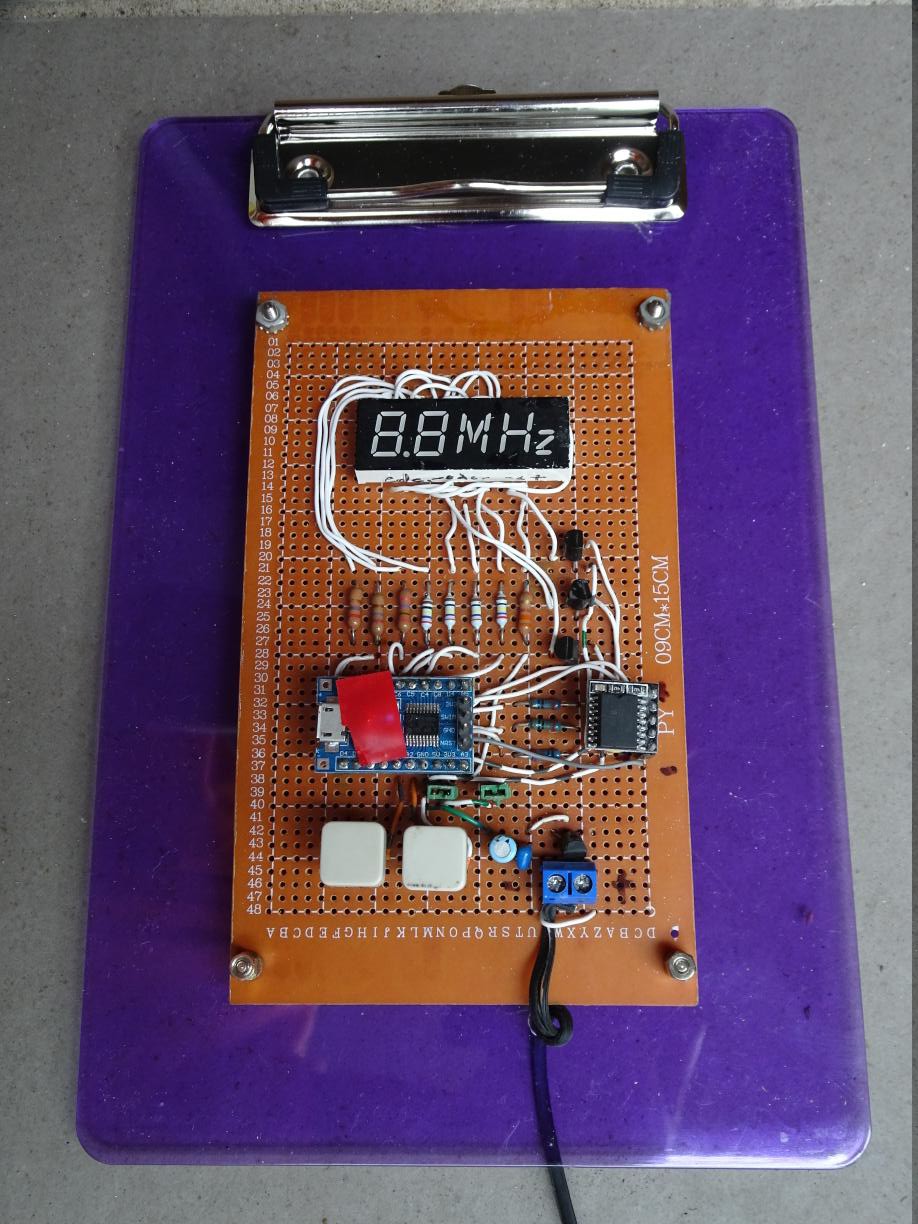
As I have only one display, it would be a waste to get at least 5 fabricated by a PCB house, and there would be a long shipping delay, unless I pay even more for expedited shipping. So I wired up the project on a perfboard. It's ugly, and even worse on the other side so I won't show that.
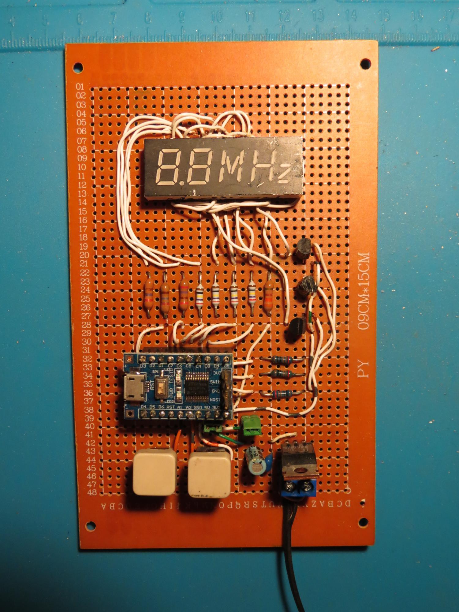
By the way the buttons are also recycled from PCs; they used to be reset buttons. The power supply is a recycled Nokia charger, feeding a 7805 voltage regulator.

There were quite a few joints to solder, that's what happens when you turn a non-multiplexed display into a multiplexed one, so I was glad I was only making one board. Testing showed besides a handful of short circuits and dry joints, a couple of boo-boos: I thought the cathode driver transistors had an EBC footprint but they were ECB. Duh. So a little rerouting of the wires. Another small rerouting was needed because I had transposed two pins of the display, swapping segments b and g of the second digit.

But eventually it passed and I connected it up to an Arduino to display a periodic pattern.

Software

SDCC supports the stm8 architecture. I needed definitions for the STM8 resources such as the registers. I wondered why they did not come with SDCC. To cut short a long adventure down a rabbit hole, it turns out that initially ST did not provide include files and libraries under a suitable license for open source. Eventually they realised their mistake but by then workarounds were swirling around the Internet. However there has been a port of the official Standard Peripherals Library to SDCC. You can read the instructions for building SPL on Linux to get the include files and the library. The advantages of using these includes and library are that: the code becomes more self-documenting, if prolix; there is some error checking of usage; and the SPL for STM32 is similar when you want to reuse the knowledge.

I also used Adam Dunkels' Protothreads for the switch handling.

Firmware for a MCU based clock has several subsystems. I indicate the C source file that handles each subsystem. It may be useful to refer to the source code.

  • The timekeeping code (tod.c) which counts subseconds, seconds, minutes and hours
  • The periodic timer (tick.c)...
Read more »

4digittest.ino

Arduino sketch used to test display. May be useful for other multiplexed displays. See the available defines in code.

ino - 2.25 kB - 10/22/2020 at 00:16

Download

  • Improving the UI

    Ken Yap11/05/2024 at 08:44 0 comments

    I got tired of HMUI which assigns the two buttons to update the hours and minutes respectively which required assigning pressing both to Enter Set Mode to avoid accidental changing of the time.

    Instead I have moved to MODEUI, where the first button cycles between Normal, Set Hours, and Set Minutes. The second button advances the hours or minutes. There is also a timeout to return to Normal after about a minute of button non-activity. It's the same MODEUI I have been deploying on my other designs.

    This required revising the code, but it was straightforward and the changes have been pushed to Github.

  • Retrofitting an RTC, part 2

    Ken Yap11/07/2021 at 21:17 0 comments

    In the last log I coded a bitbang driver for the I2C interface. I now have a working implementation that uses the STM8's silicon. The work consisted of understanding the protocol diagrams in the I2C section of the STM8L reference manual, which is for the STM8L series but also applies to the STM8S series.

    Complication arises from the fact the the silicon has a receive pipeline, so some actions have to be taken ahead of reading the data register to generate the correct I2C handshake. Obviously the pipeline exists for speed reasons, for example when reading bulk data from I2C flash memory.

    Page 107 of the manual shows different algorithms for the cases where N > 2, N = 2, and N = 1, where N is the number of bytes to read. I also had to consult the example code in stm8s_eval_i2c_ee.c which is a driver for EEPROM. It turns out that it's not sufficient to use just I2C_CheckEvent, one must also use I2C_GetFlagStatus. I have only implemented the N > 2 case as I want 7 bytes from the RTC, so the routine is not general purpose. Bear this in mind if you want to reuse the routine.

    The labelled events in the protocol diagram correspond to enum values for the I2C_CheckEvent call defined in the SPL I2C includes. Strictly speaking I should have a timeout on expected events so that MCU doesn't get stuck if an event doesn't arrive. Or perhaps I should use the Watchdog Timer. Anyway I now have two working versions of the I2C driver which can be selected at build time. Since there is still plenty of flash space and MCU power, it makes little difference in practice which one is incorporated. The silicon I2C driver is canonical and doesn't rely on using TIM1 for the delays; you know that the silicon is working as efficiently as designed.

    The board was mounted on an A5 acrylic clipboard and I can now finally close off this project.

    Here is the gory receive routine:

    void rtc_getnow(void)
    {
            // send pointer of 0
            I2C_GenerateSTART(ENABLE);
            while (!I2C_CheckEvent(I2C_EVENT_MASTER_MODE_SELECT))
                    ;
            I2C_Send7bitAddress(DS3231ADDR << 1, I2C_DIRECTION_TX);
            while (!I2C_CheckEvent(I2C_EVENT_MASTER_TRANSMITTER_MODE_SELECTED))
                    ;
            I2C_SendData(0);
            while (!I2C_CheckEvent(I2C_EVENT_MASTER_BYTE_TRANSMITTED))
                    ;
    
            I2C_GenerateSTART(ENABLE);                      // generates a restart
            while (!I2C_CheckEvent(I2C_EVENT_MASTER_MODE_SELECT))
                    ;
            I2C_Send7bitAddress(DS3231ADDR << 1, I2C_DIRECTION_RX);
            while (!I2C_CheckEvent(I2C_EVENT_MASTER_RECEIVER_MODE_SELECTED))
                    ;
            // read sizeof(now) (7) bytes
            I2C_AcknowledgeConfig(I2C_ACK_CURR);            // ACK
            uint8_t i = 0;
            while (i < sizeof(now) - 3) {
                    while (!I2C_CheckEvent(I2C_EVENT_MASTER_BYTE_RECEIVED))
                            ;
                    now[i] = I2C_ReceiveData();
                    i++;
            }
            // third last byte
            // wait for BTF
            while (I2C_GetFlagStatus(I2C_FLAG_TRANSFERFINISHED) == RESET)
                    ;
            I2C_AcknowledgeConfig(I2C_ACK_NONE);            // NAK
            now[i] = I2C_ReceiveData();                     // N-2
            i++;
            // second last byte
            I2C_GenerateSTOP(ENABLE);
            now[i] = I2C_ReceiveData();                     // N-1
            i++;
            // last byte
            // wait for RXNE
            while (I2C_GetFlagStatus(I2C_FLAG_RXNOTEMPTY) == RESET)
                    ;
            now[i] = I2C_ReceiveData();                     // N
            unpack_time();
    }

  • Retrofitting an RTC, part 1

    Ken Yap11/03/2021 at 00:09 0 comments

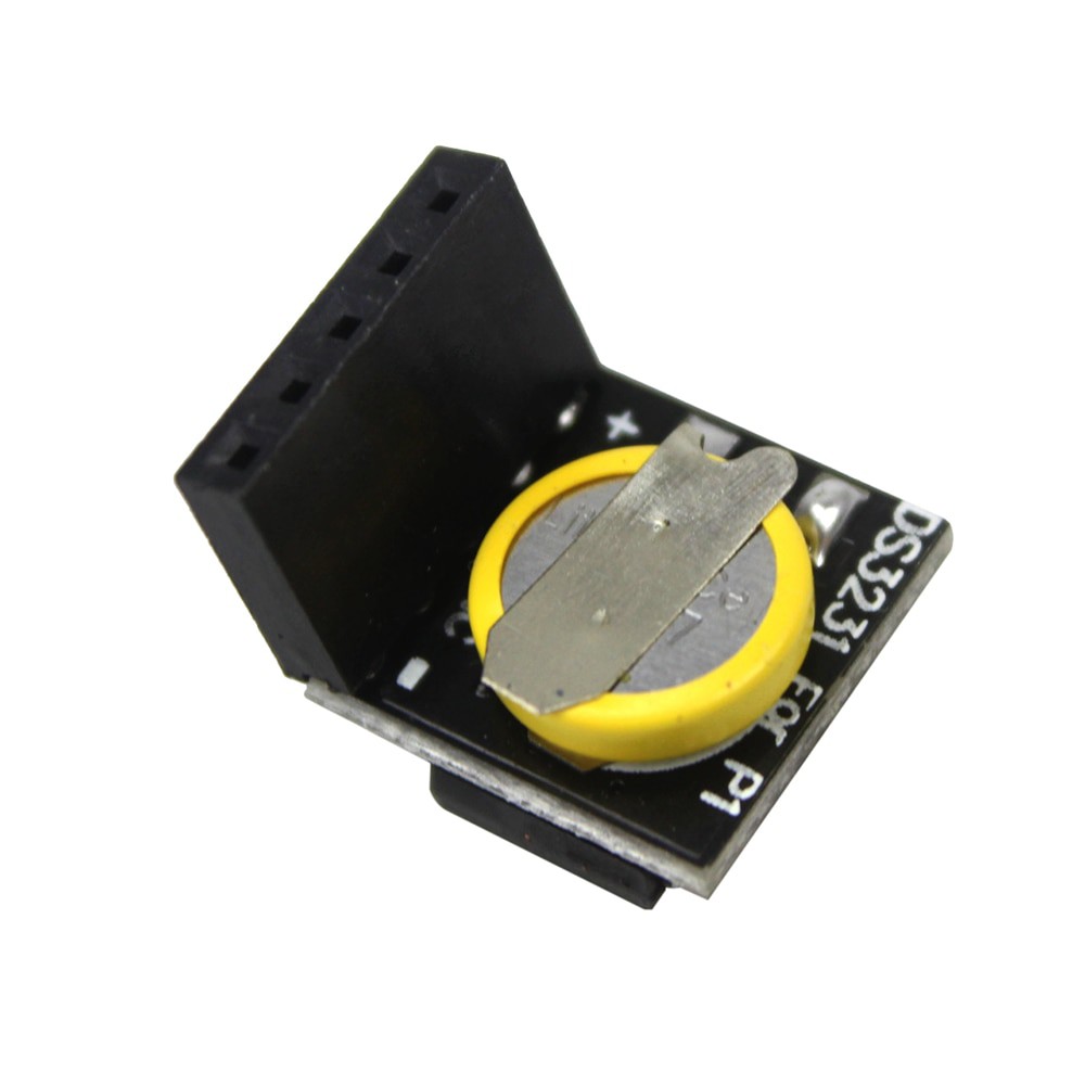
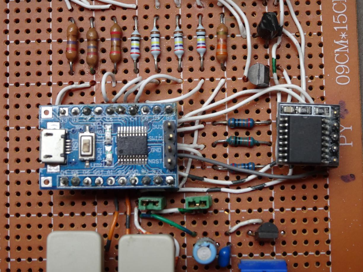
    Photo of board with added RTC on right, plugged into 5-pin header.

    While it is possible to tune the onboard oscillator to give a semblance of accuracy in timekeeping, this is tedious and only really works for a small temperature range. So I looked into ways of improving the accuracy. A DS3231 based RTC will provide a great improvement at little cost, only a couple of dollars.

    Fortunately the B4 (SCL) and B5 (SDA) lines on the STM8 board are still available. I added a 5-pin header to the prototype board and connected 4 lines to the MCU. Vdd goes to the 3.3V supply (actually 5V as it's running at 5V, but the RTC can handle that), GND to GND of course, and SCL to B4 and SDA to B5. A couple of 4k7 pullup resistors to Vdd complete the addition.

    I started coding using the I2C routines in the Standard Peripheral Library but discovered that the I2C interface is quite comprehensive and needs a good understanding of the various events in the I2C protocol.

    So I coded an alternate implementation to get basic experience with this RTC, using bit-banging with the GPIO routines on the same two pins. I thought it should work first go after a clean compile as the code had been tested before on other processors. However I was over-optimistic as there were a couple of things I didn't anticipate. The first is that I had been spoiled by the 8051 pins which have weak pullup and thus don't have to be explicitly switched between input and output. In places in the protocol, one has to switch the SDA pin to input. The second is that the GPIO_ReadInputPin routine doesn't return 0 or 1, but rather 0 and !0, the difference being anything non-zero qualifies as !0. In particular the routine returns the bit in the SDA position which is B5 or 2^5. So one part of the byte assembly routine has to be changed from

    data |= GPIO_ReadInputPin(GPIOB, GPIO_PIN_5);

    to

    data |= GPIO_ReadInputPin(GPIOB, GPIO_PIN_5) ? 1 : 0;

    Being able to observe the program in action using PlatformIO was a great help debugging.

    I will get back to coding the native I2C implementation after digesting the I2C section of the STM8L reference manual, which is for the STM8L series but also applies to the STM8S series.

    A remark: If you had modified the design to accommodate a more conventional 4 digit display, then the only line left for driving the 4th digit is D1 (SWIM) which means you have to decouple that line for flashing or debugging. Other solutions are to get a STM8 with a larger set of GPIO lines, or to use a decoder or shift register to drive the digits so that you don't need more than 2 or 3 digit outputs.

  • Small tweaks to firmware

    Ken Yap10/06/2021 at 09:54 0 comments

    I've made a couple of small tweaks to the firmware.

    • The buttons can be accidentally pressed and the time changed. Now you have to depress both buttons together to enter set mode and the display will blank 0.5 seconds. After 8 seconds of button inactivity after setting, it will exit set mode.
    • The DDS adjustment can be specified in the Makefile, instead of editing tod.c

    I doubt if anybody else has this clock but you may find the techniques useful.

View all 4 project logs

Enjoy this project?

Share

Discussions

Paul McClay wrote 11/06/2024 at 04:41 point

12H 34M ...and 45 secondz

  Are you sure? yes | no

Ken Yap wrote 10/26/2020 at 05:44 point

Again? Must be a slow day at HaD. 🤣 Anyway I had fun dreaming and making it, so I hope readers have fun too. 😀

  Are you sure? yes | no

Thomas wrote 10/20/2020 at 20:43 point

That's pretty ... whacky :-) Not a very high WAF I guess but ... neat.

Recently I received some nice and chunky VFDs, and I guess that I'll spend one of those nice (and smelly) Chinese 9x15cm protoboards on them.

  Are you sure? yes | no

Ken Yap wrote 10/20/2020 at 22:56 point

I like VFDs. Pity I don't have VFDs in my spares box, so I guess i'll have to do something with the nixies.

  Are you sure? yes | no

Ken Yap wrote 10/21/2020 at 12:54 point

Should have thought of it sooner, but I've added a link to your wiki on STM8 breakout boards.

  Are you sure? yes | no

Thomas wrote 10/21/2020 at 16:50 point

Thanks - links are always good :-)

  Are you sure? yes | no

Similar Projects

Does this project spark your interest?

Become a member to follow this project and never miss any updates