 Dominik Meffert
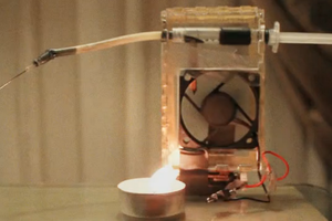
In my last inkjet project I built a piezo inkjet printer from scratch made of cheap electronics, pneumatic and 3D printed parts. I could get it to work, but I had a few problems with the reliability. The drop size was quite large, keeping the ink supply pressure steady was quite difficult and sometimes there formed drops on the nozzle or air got sucked into the printhead what both prevented the printhead from working. There also was a problem with clogging of the nozzle when not in use.
So I looked for a more reliable printing method and choosed Continuous Inkjet Printing.
CIJ printing is (as far as I know) only used in industrial or production applications and therefore super reliable. CIJ printers are working for years 24/7 with only minor maintenance.
Even though CIJ printers have much more parts than piezo or thermal inkjet printers, all parts have a decent size - no sub millimeter dimension like piezo and thermal inkjet nozzles, so working on them, fixing problems and maybe also manufacturing them will be a lot easier.
How CIJ Printing works:
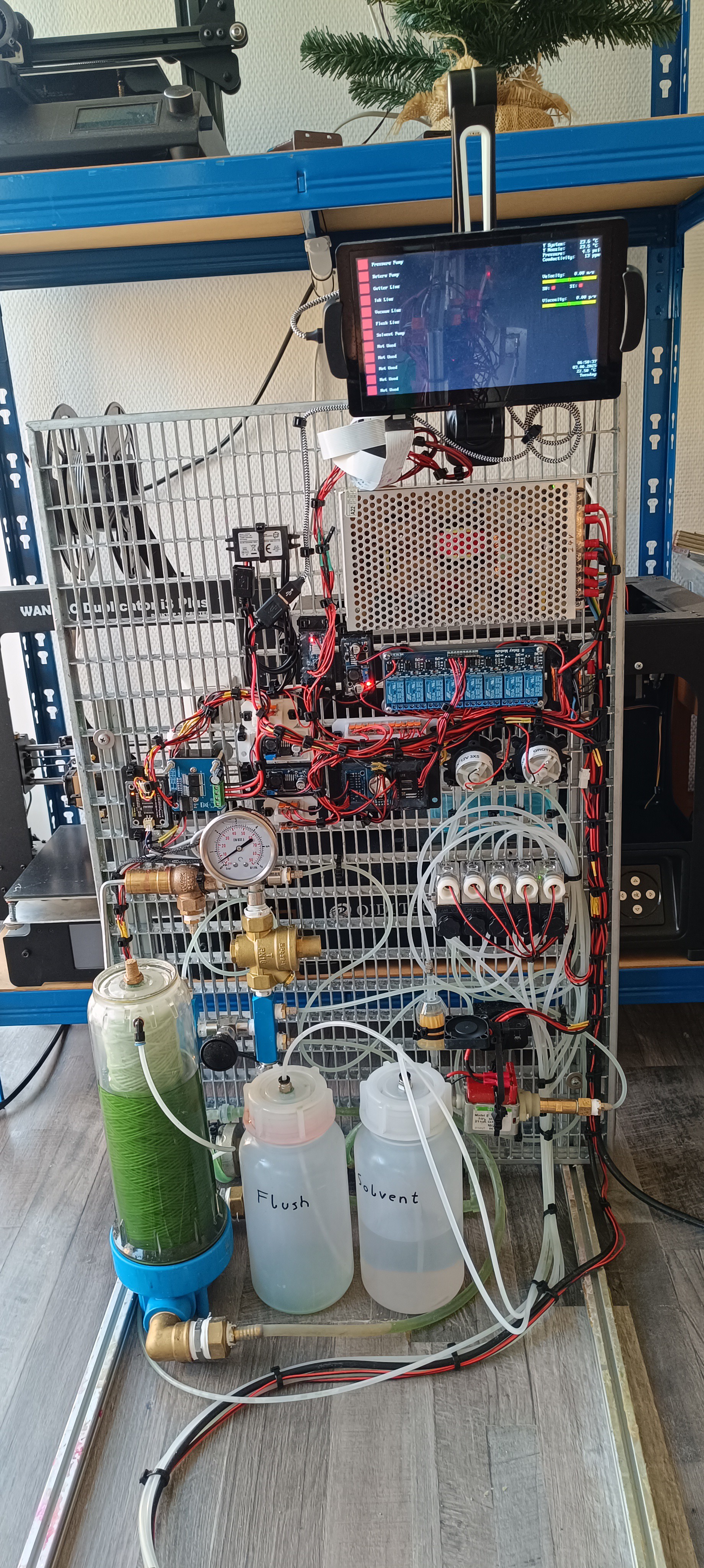
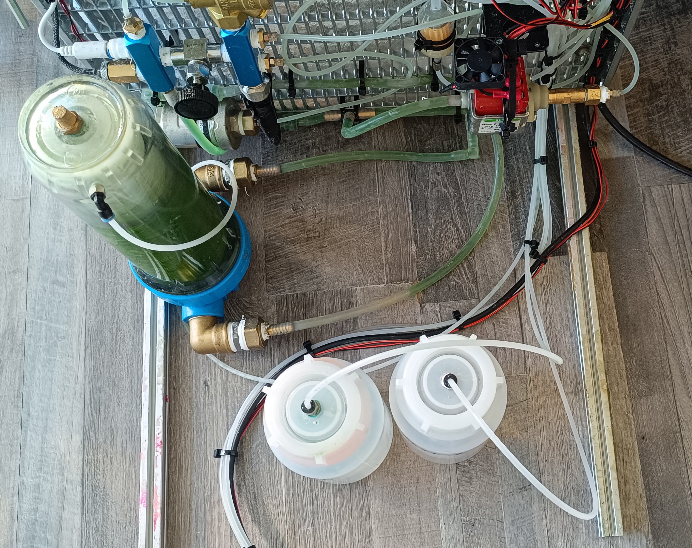
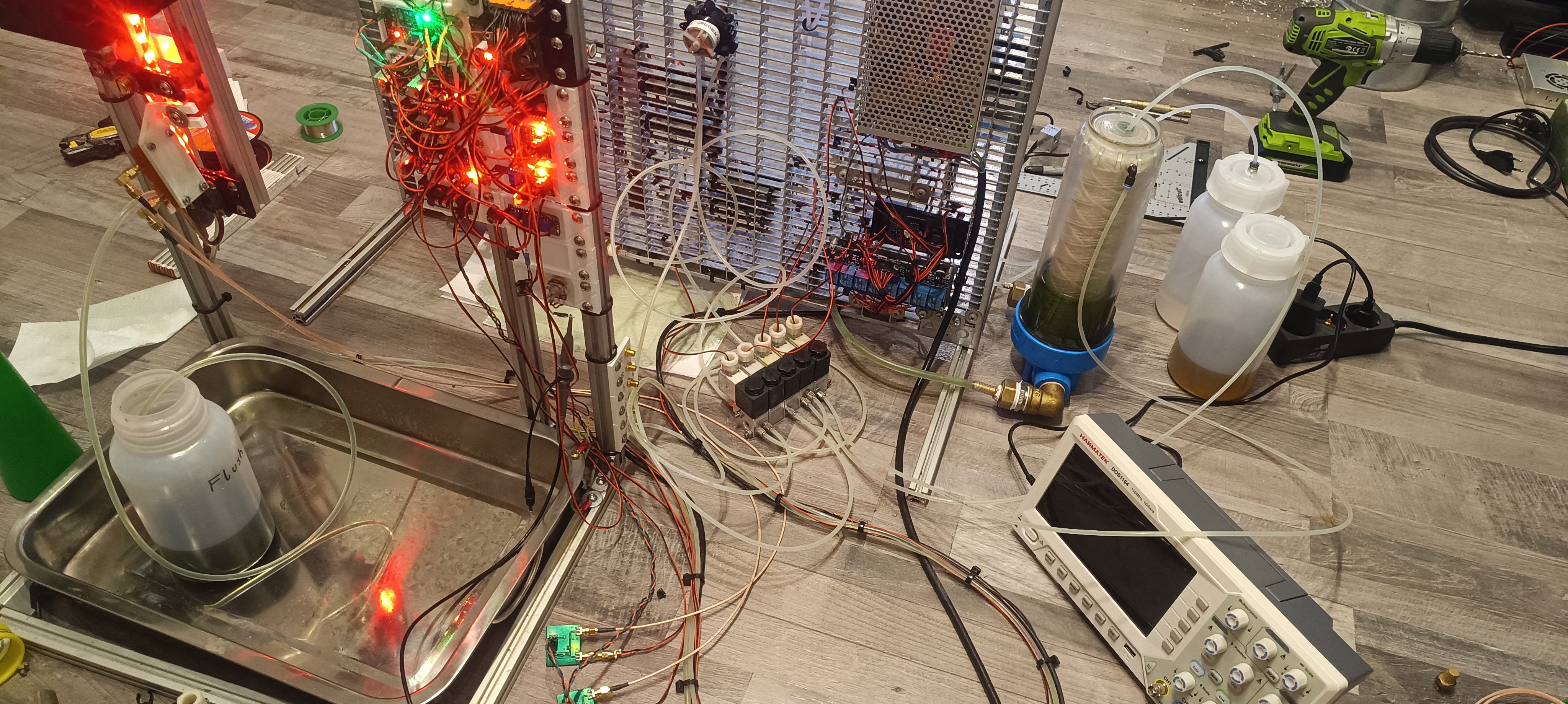
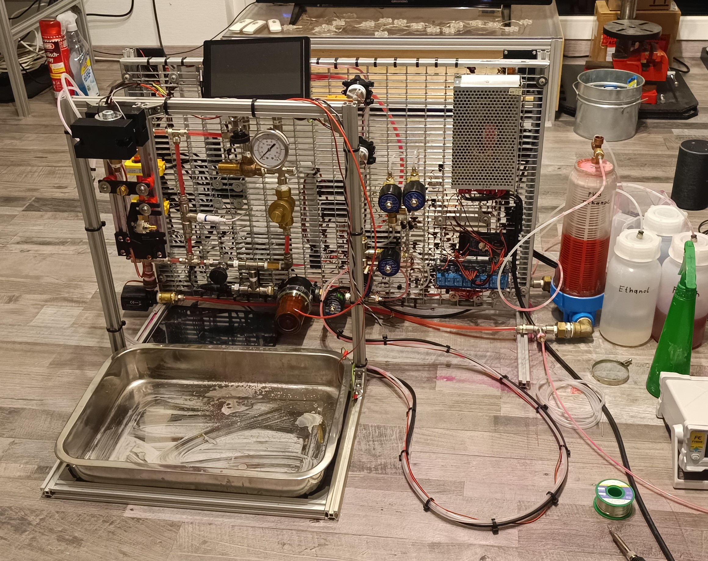
Here I will describe you in my own words based on my experience with my printer model how CIJ Printing works. The printer I have is an older model that uses pressurized air and vacuum instead of a special ink pump, what I think is really cool because it keeps everything simple and you can use any air and vacuum supply that you want.
Animation from Wikipedia
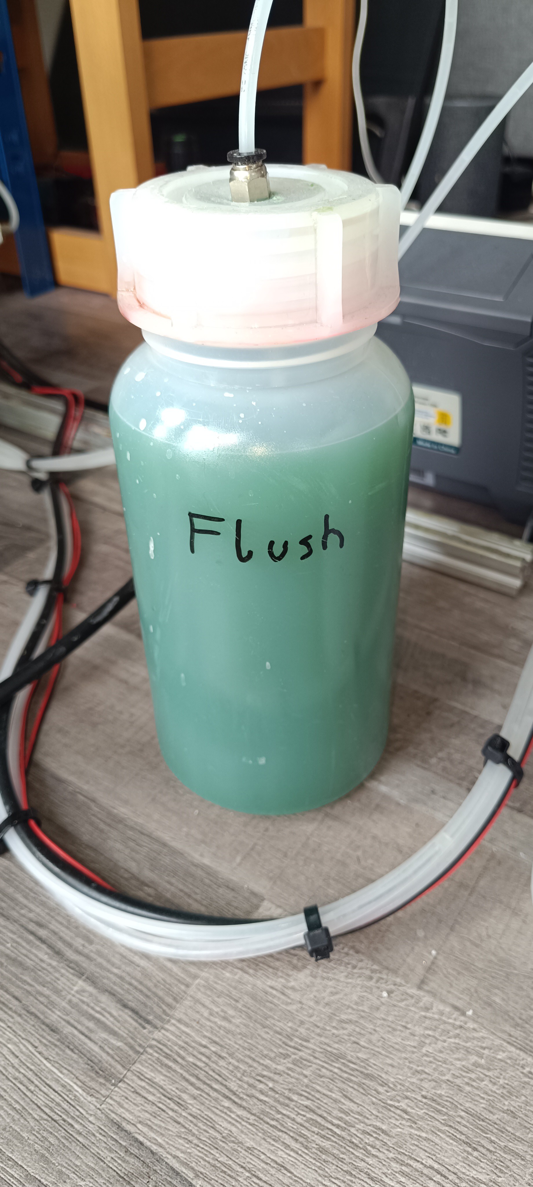
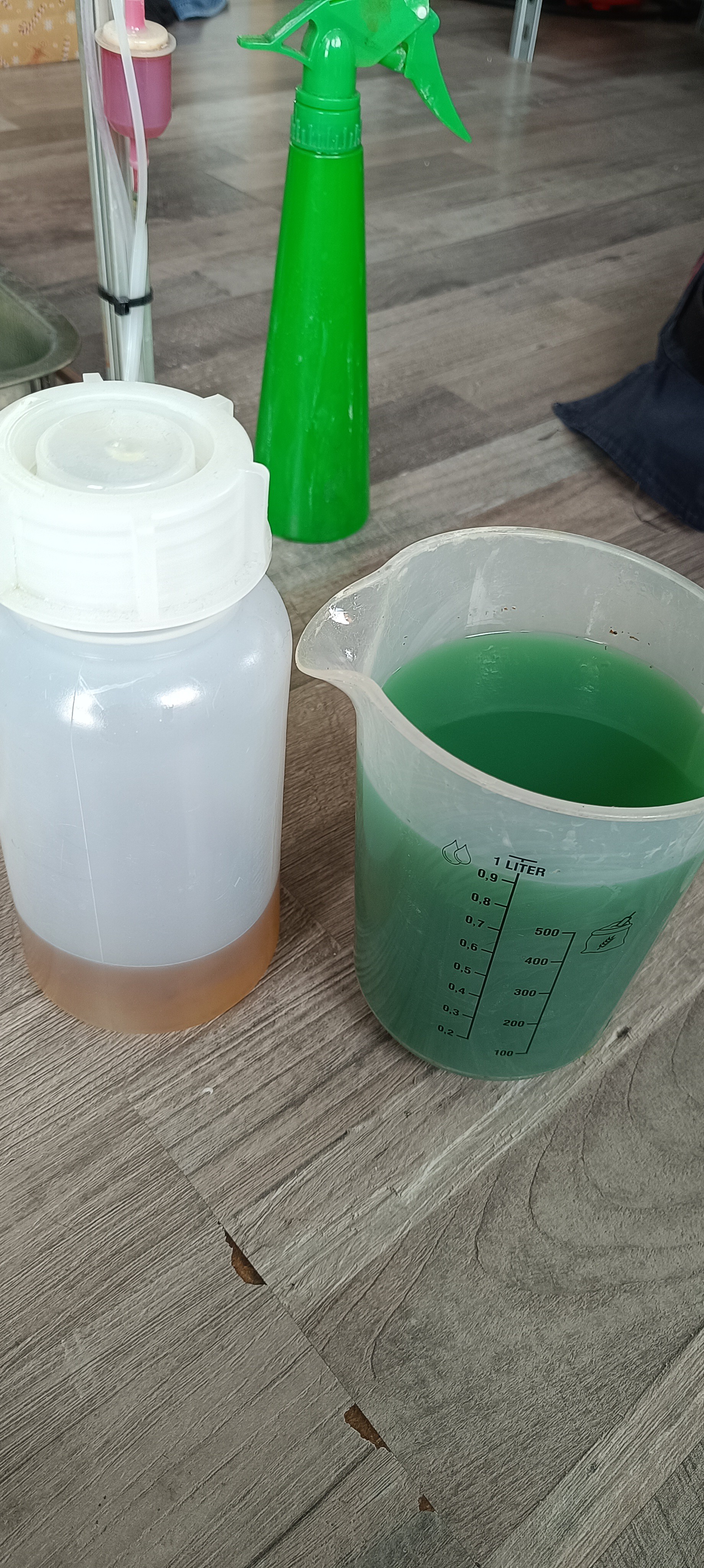
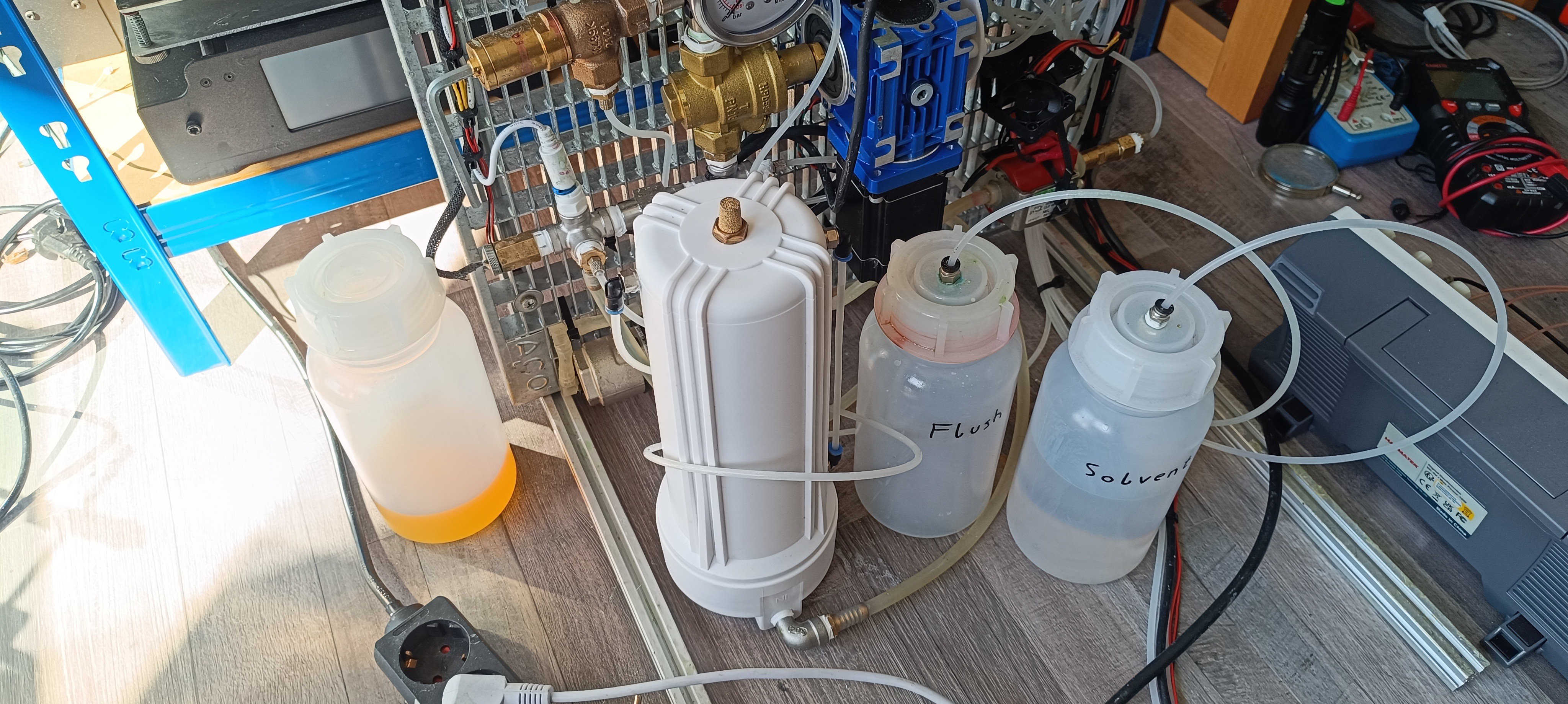
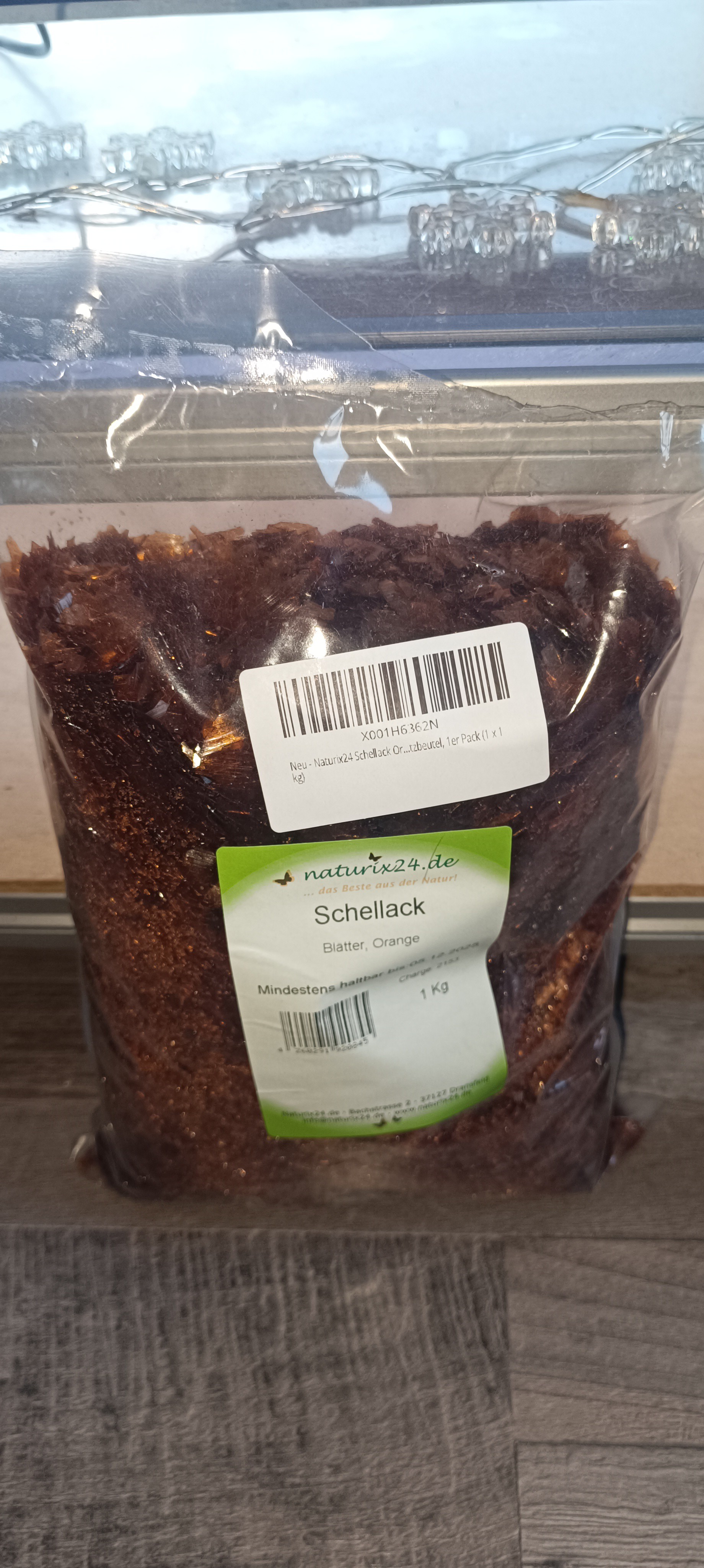
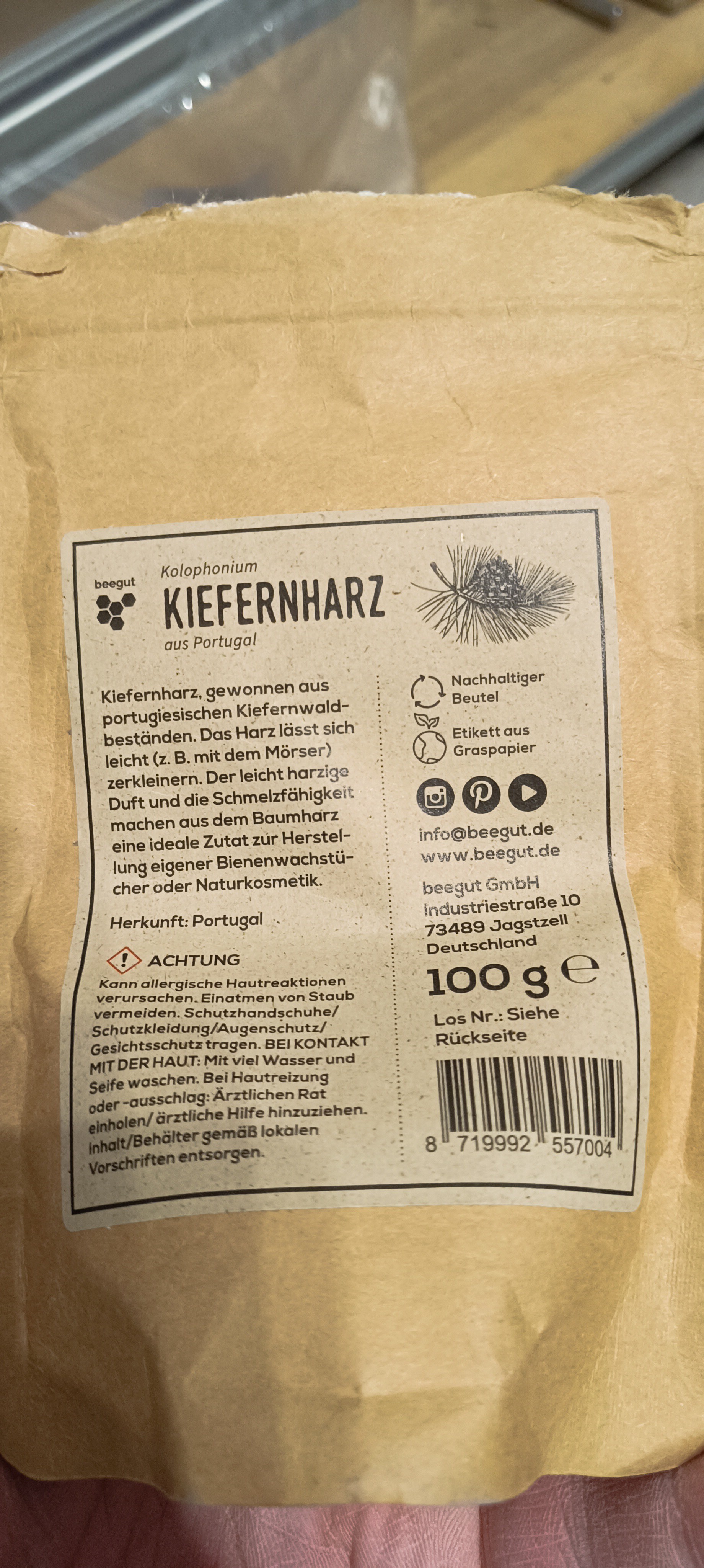
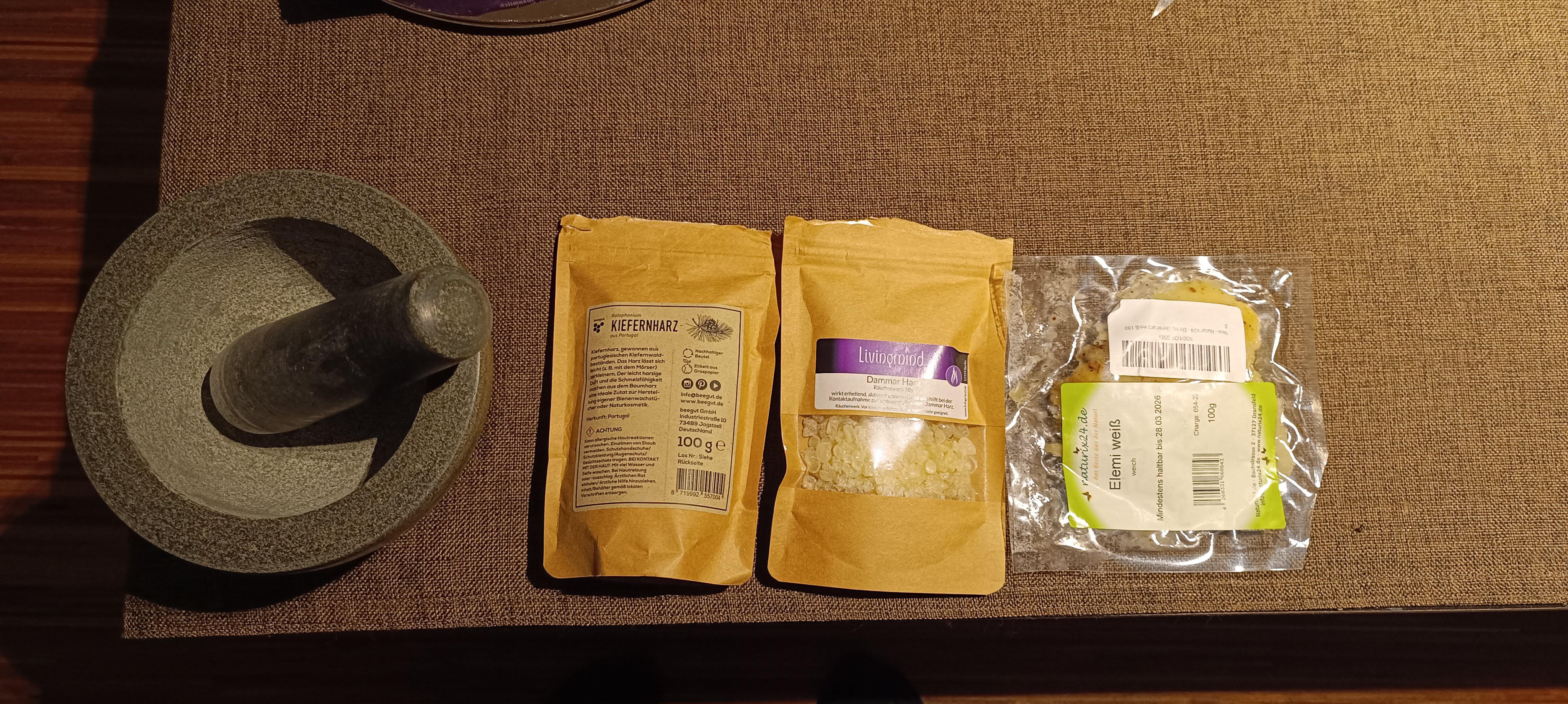
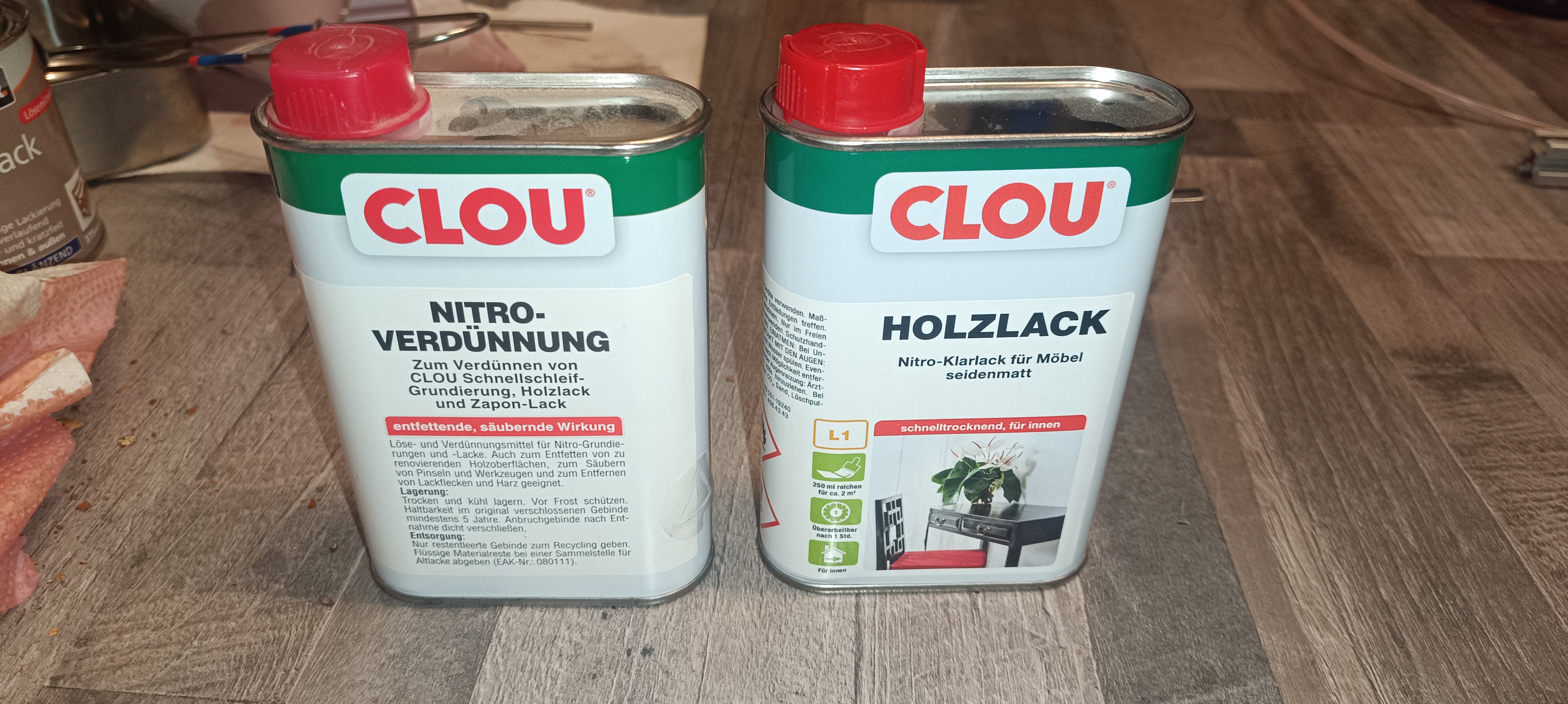
CIJ printers need two different fluids to work - Ink and Make Up Fluid.
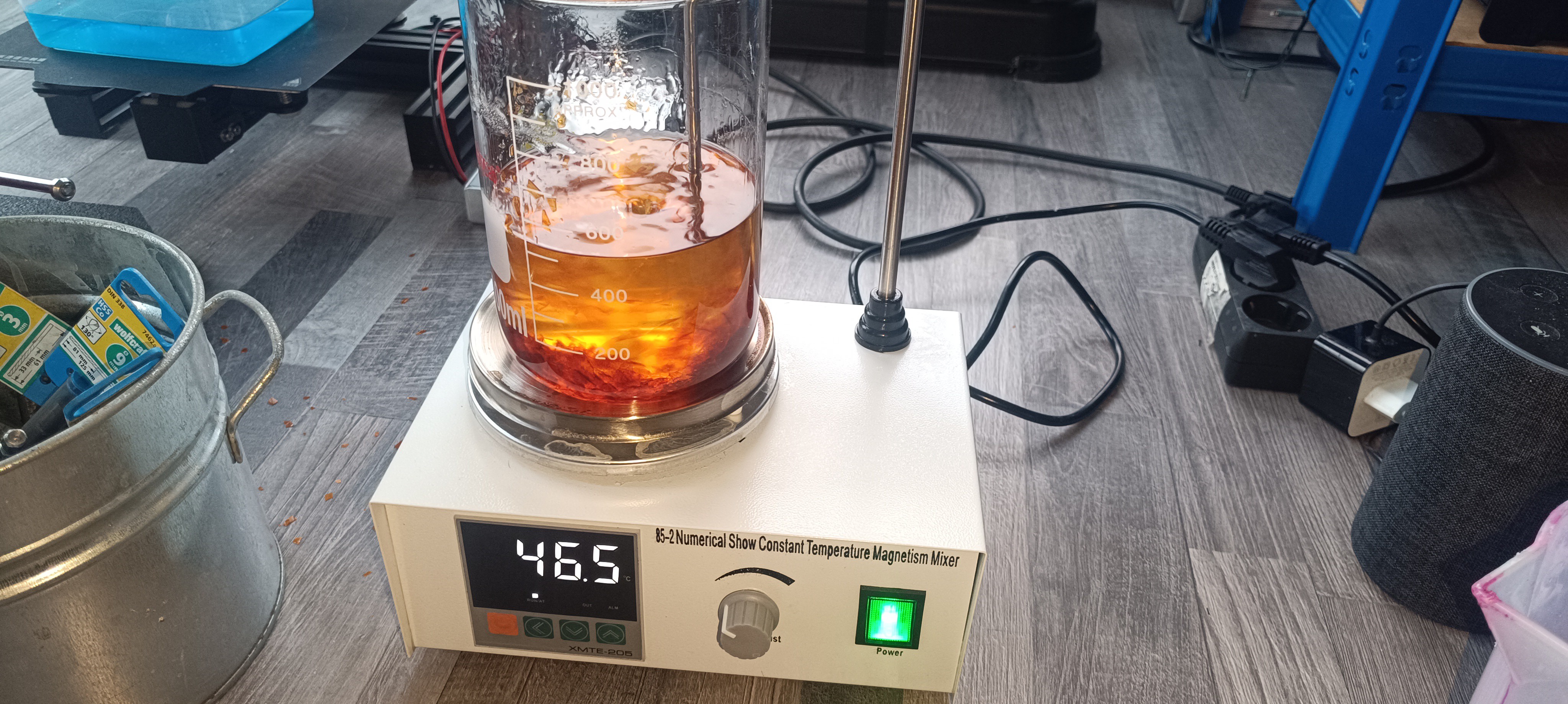
Both fluids get mixed by the printer to reach the right viscosity. The make up fluid is essentially a solvent to dilute the ink.
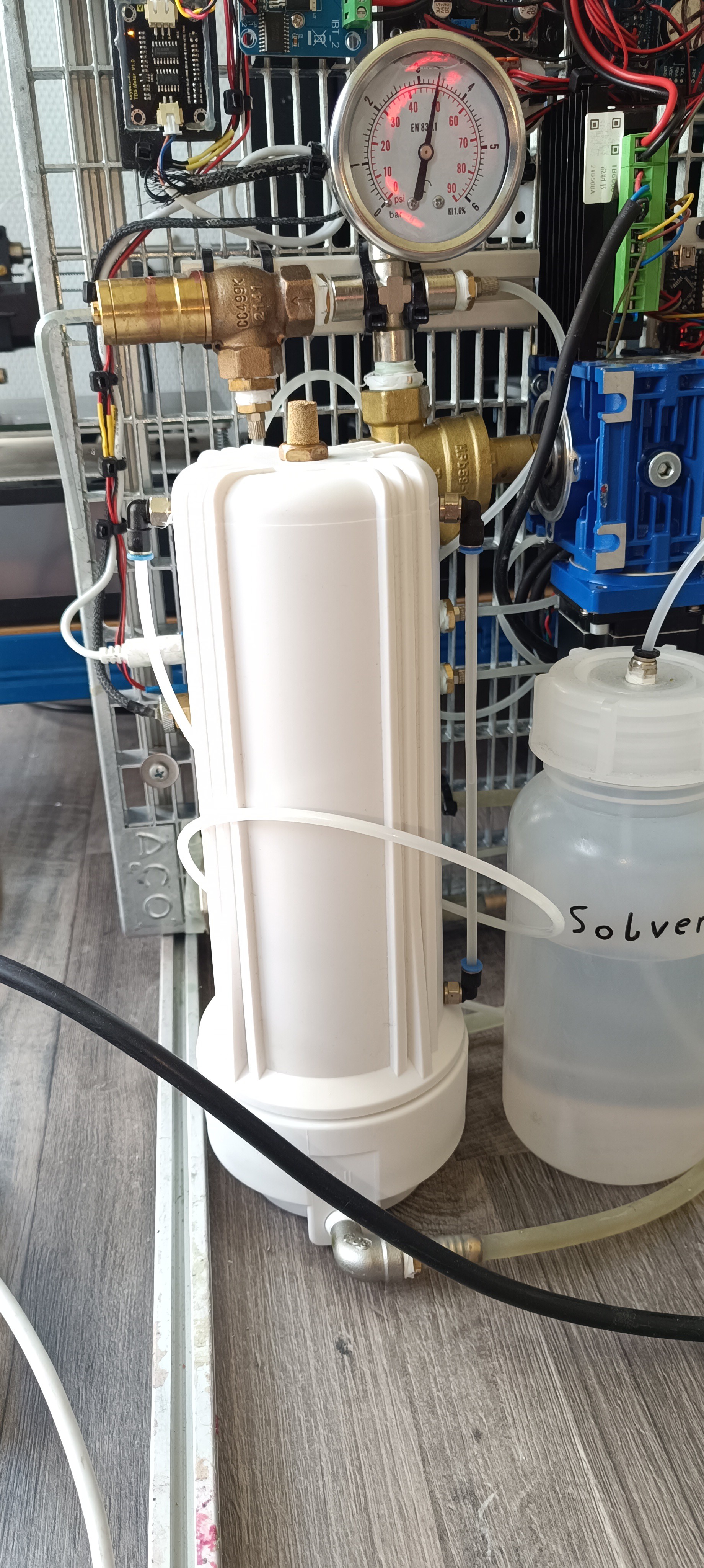
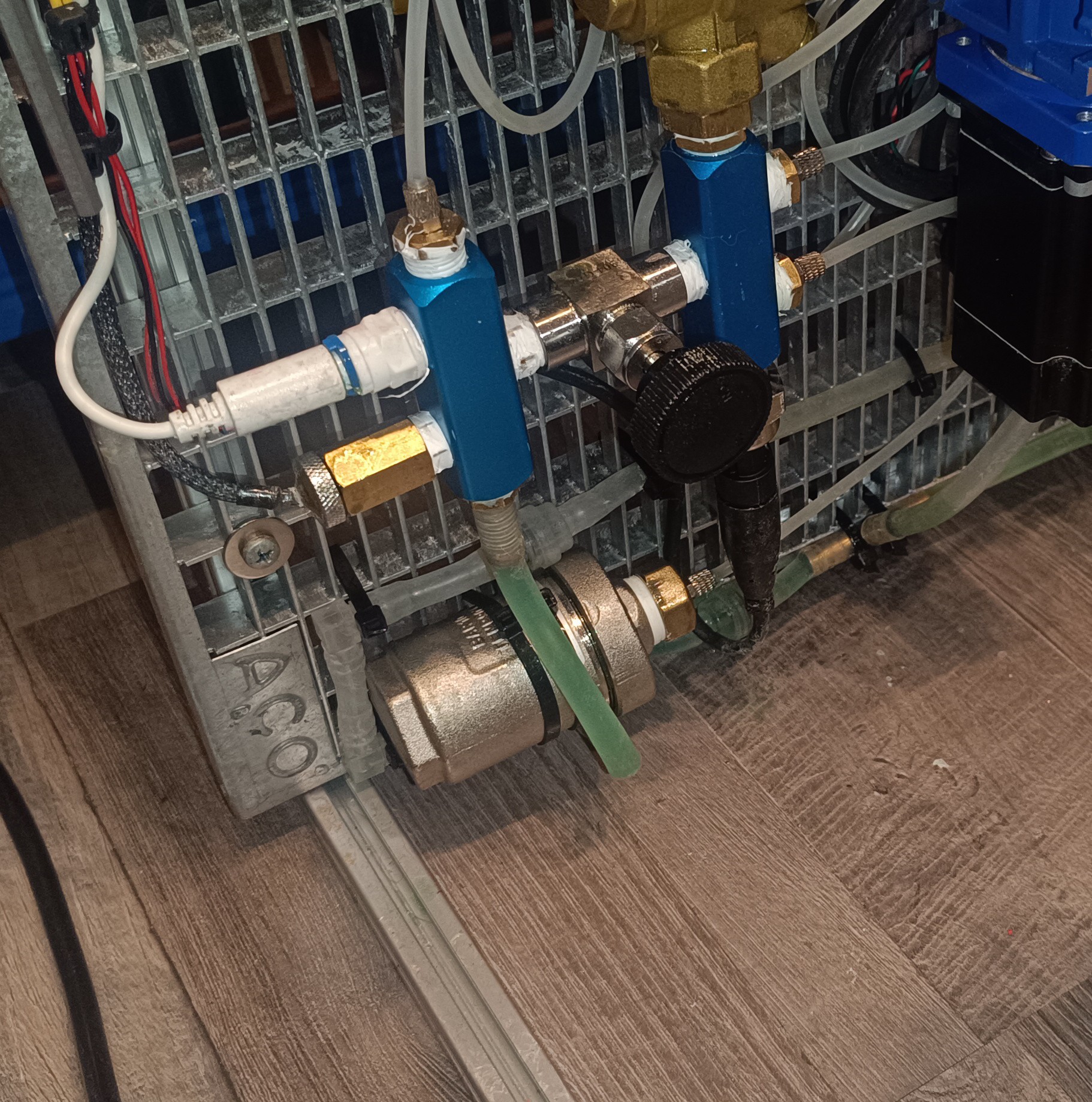
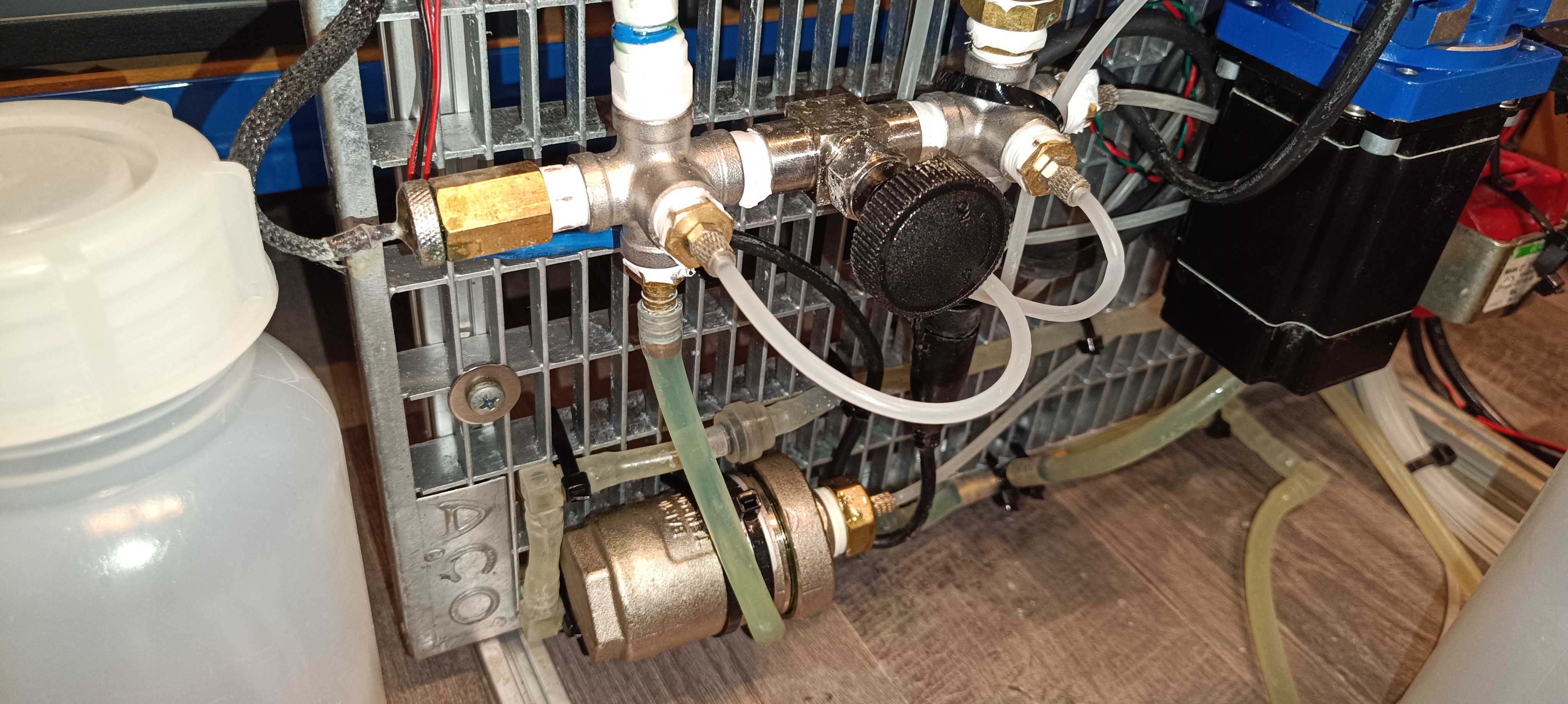
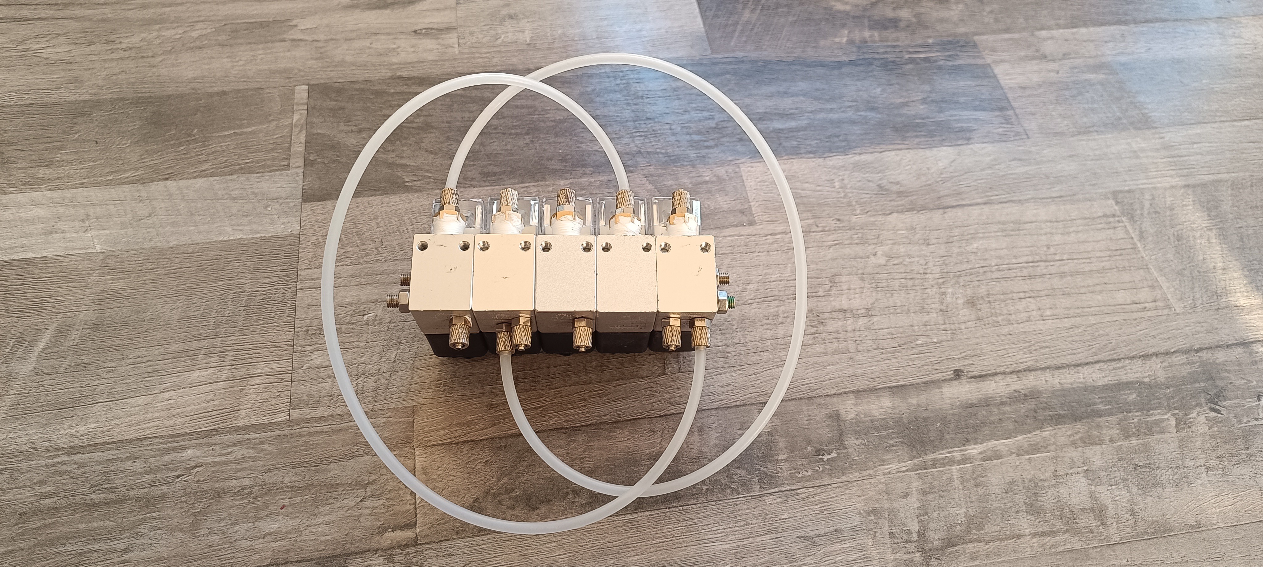
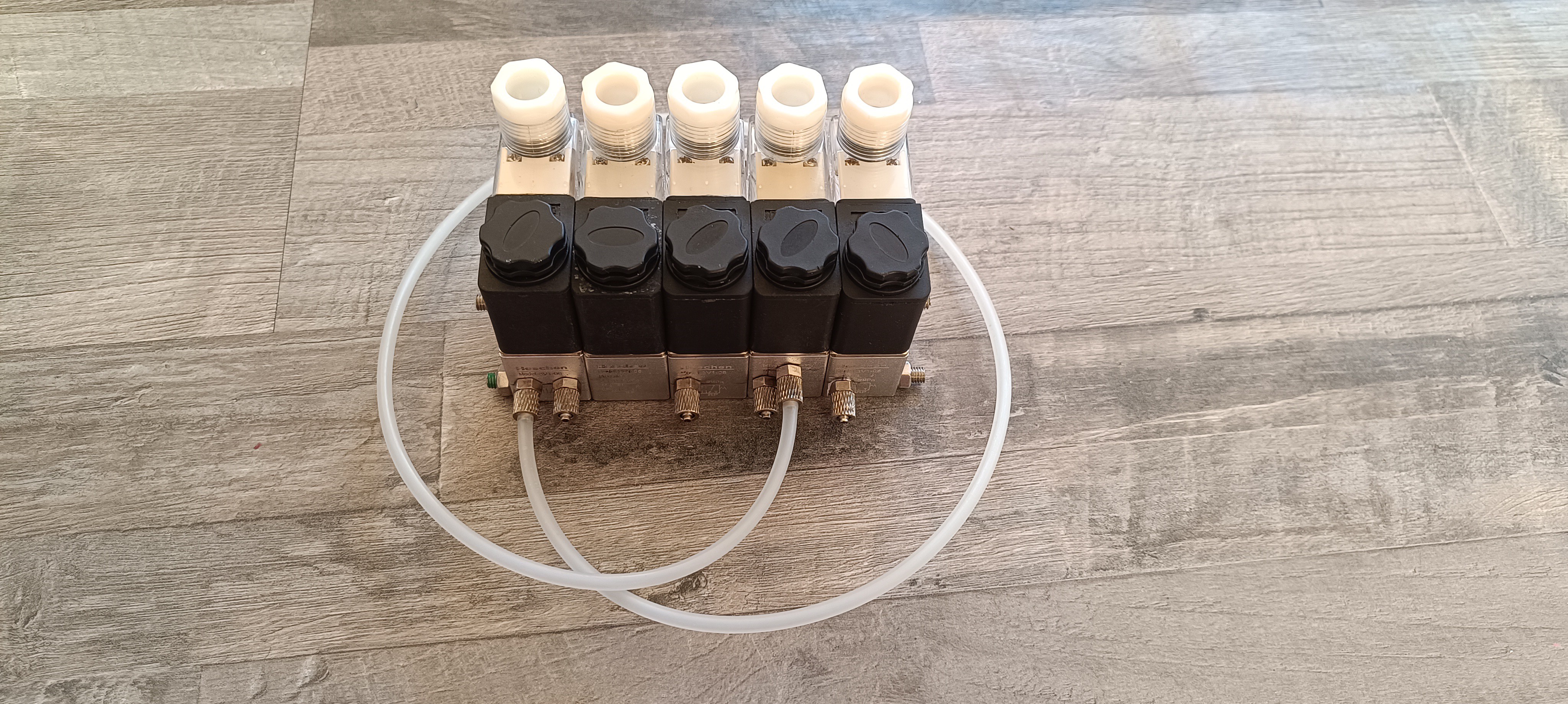
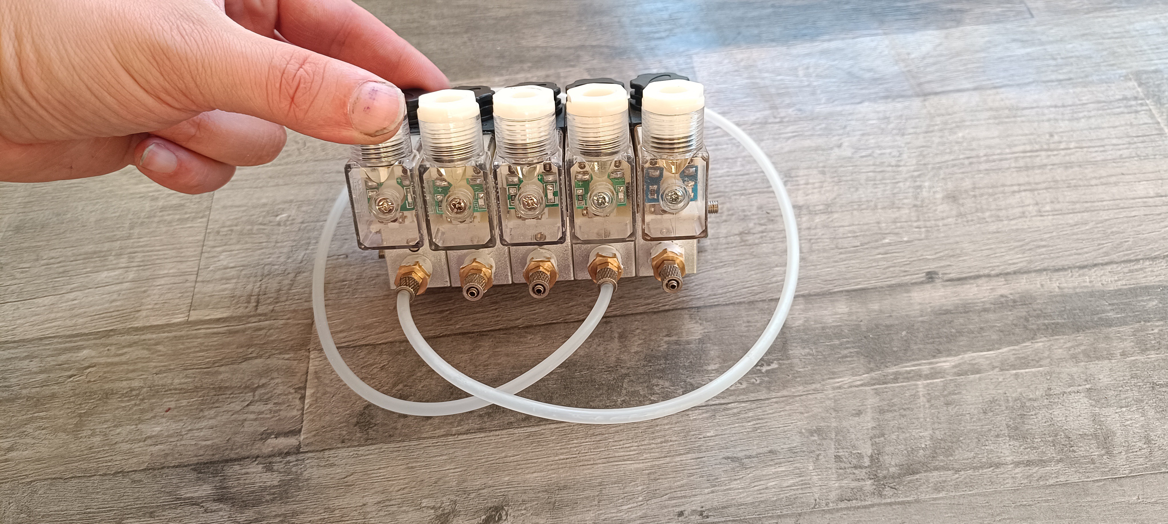
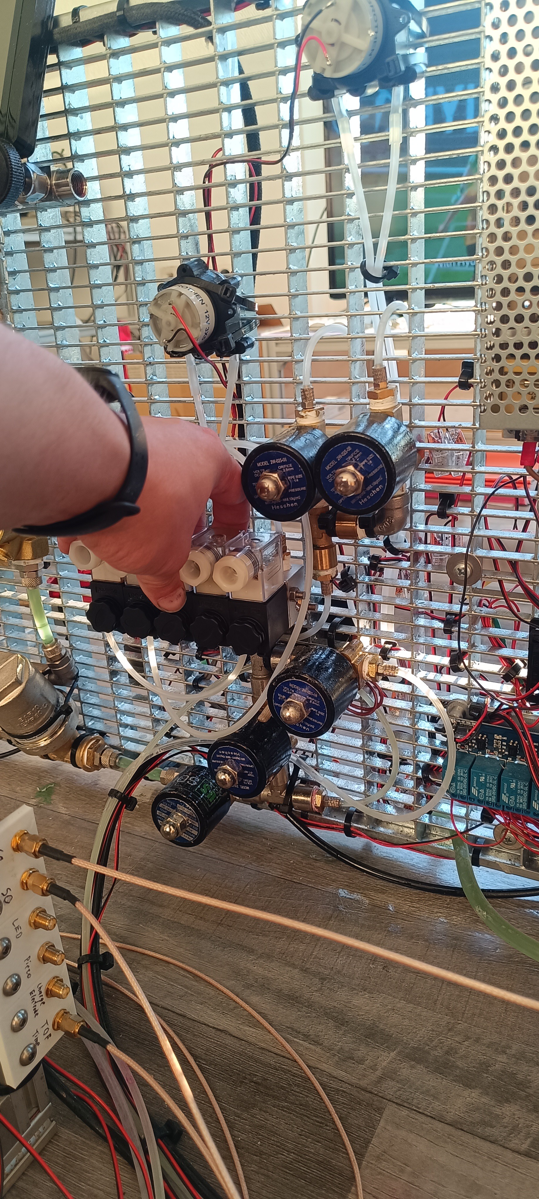
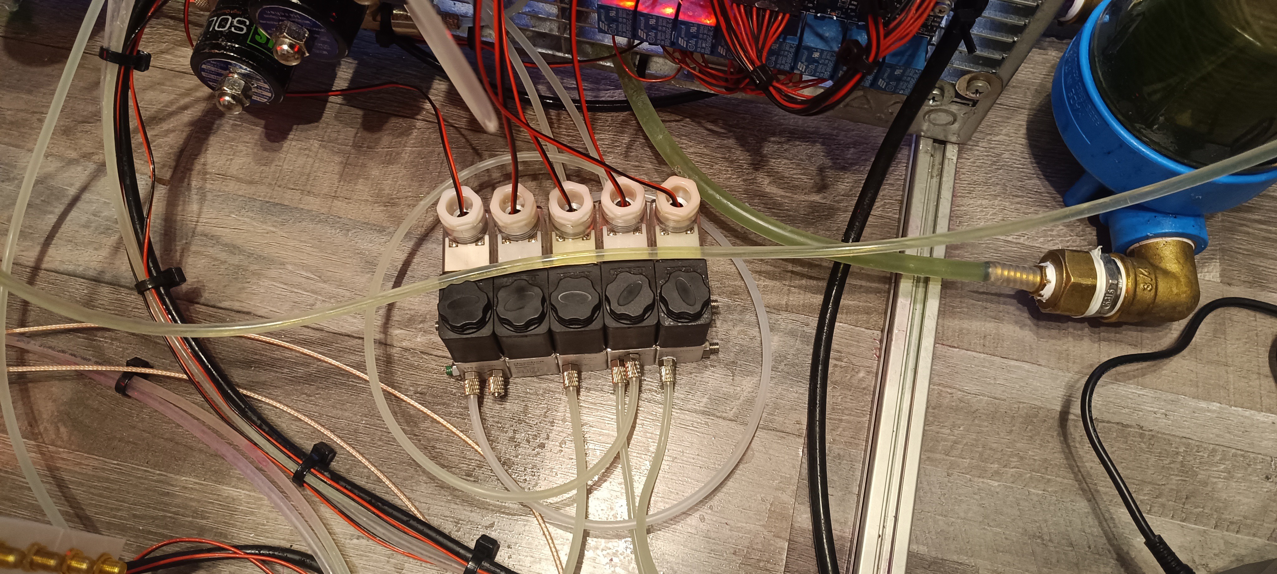
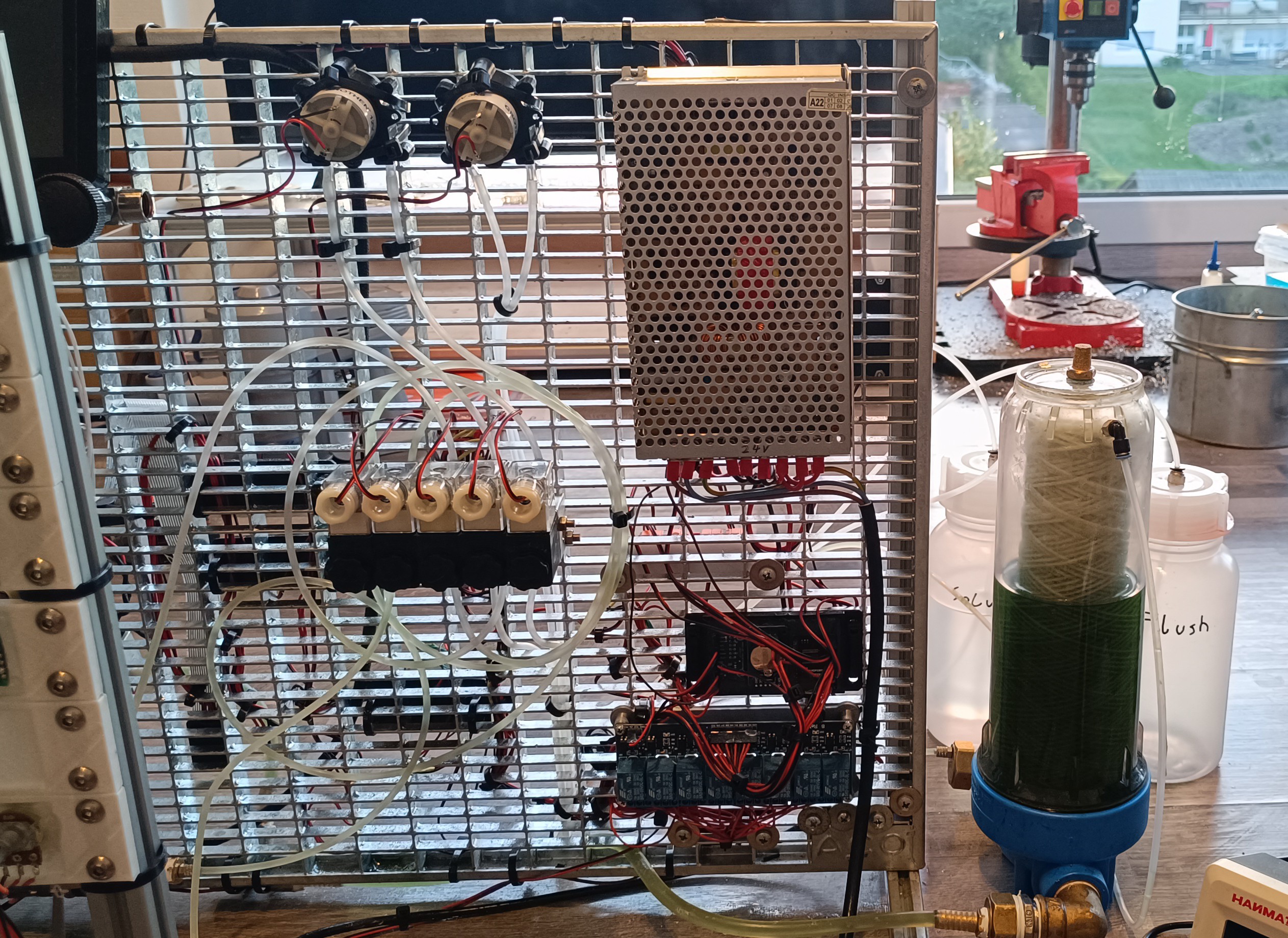
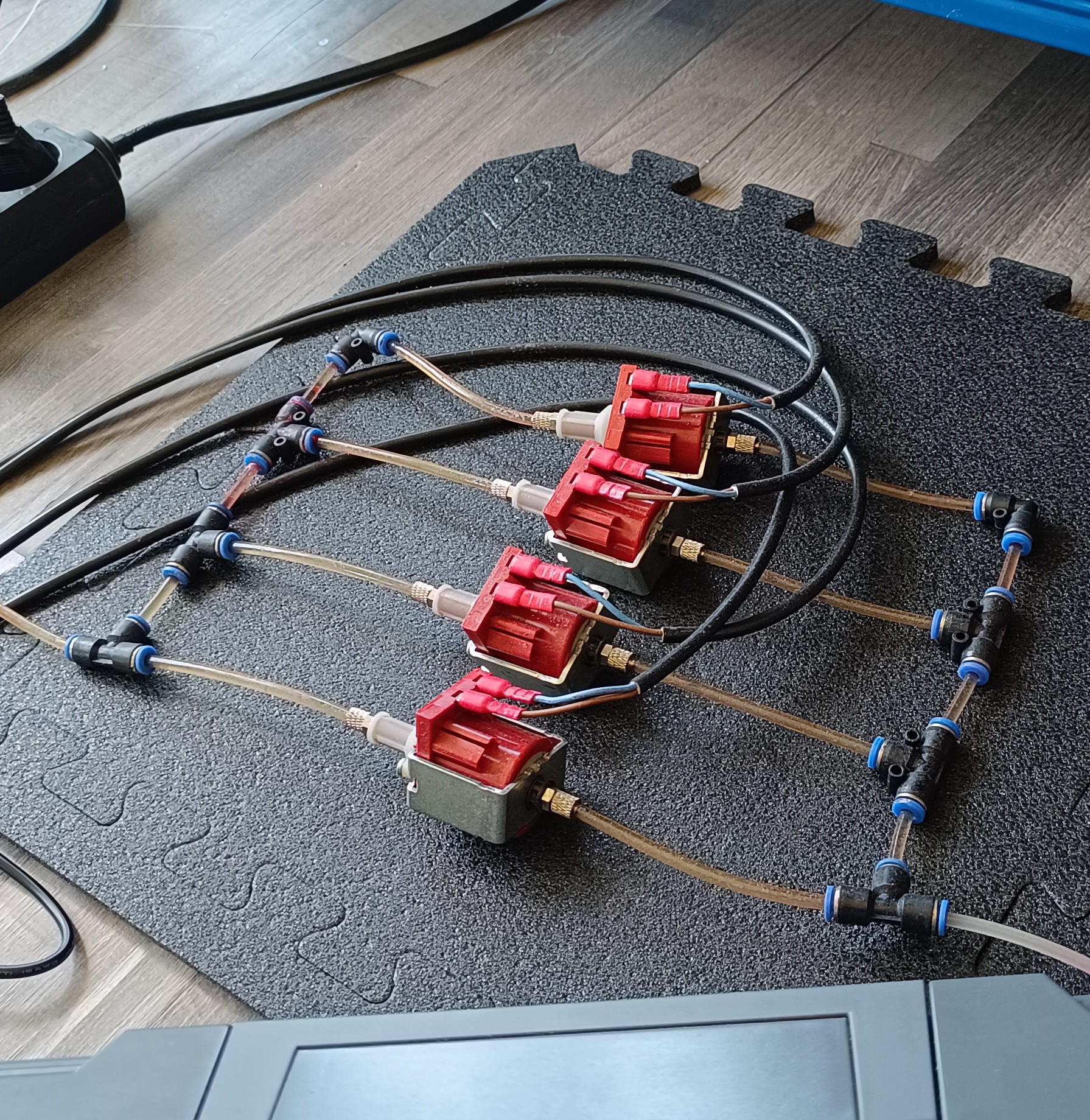
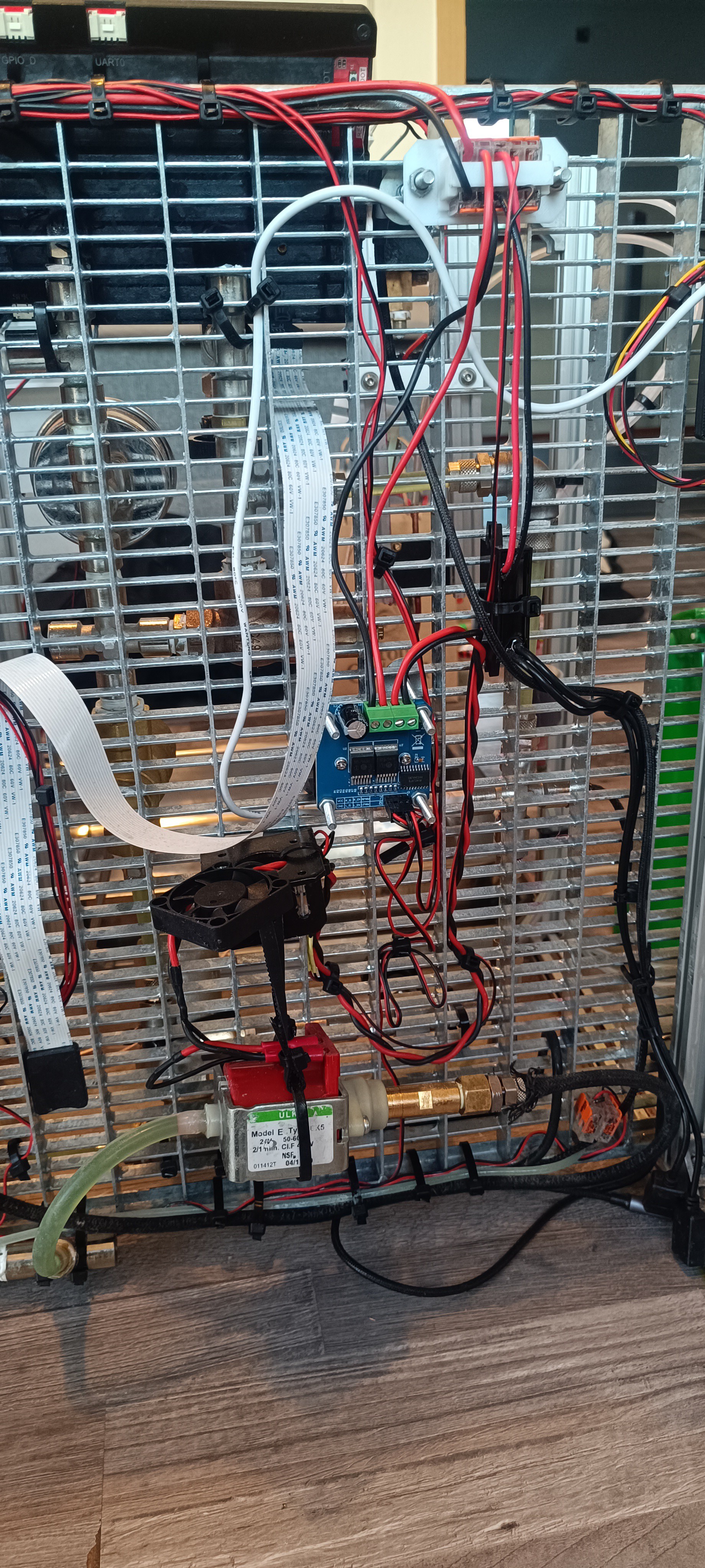
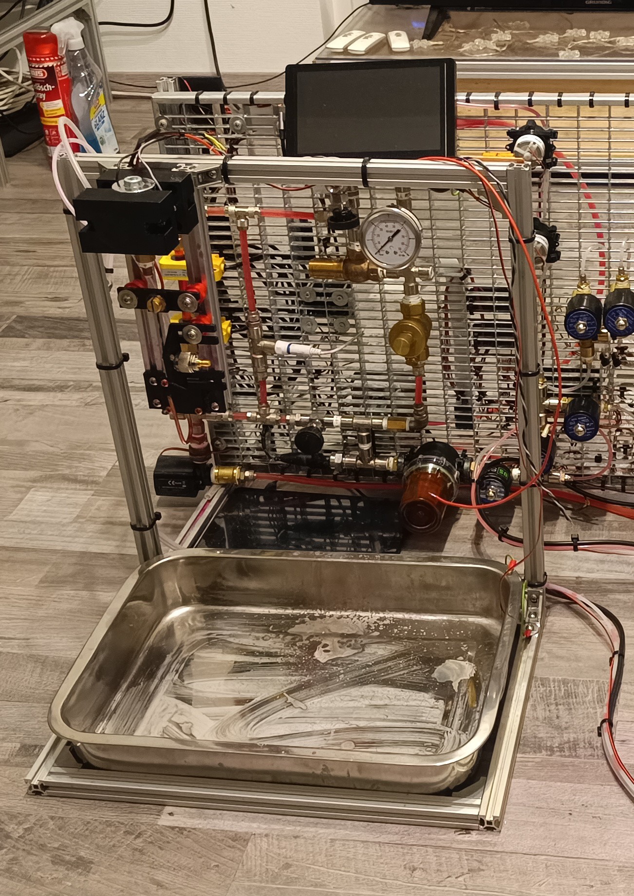
My printer has an ink mixing assembly in which the ink get mixed and also the not used ink returns to. The chamber of it is set under vacuum and the adding of ink and make up fluid is controlled by two pneumatic driven rubber valves.
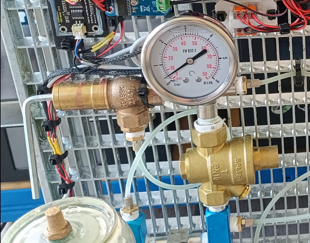
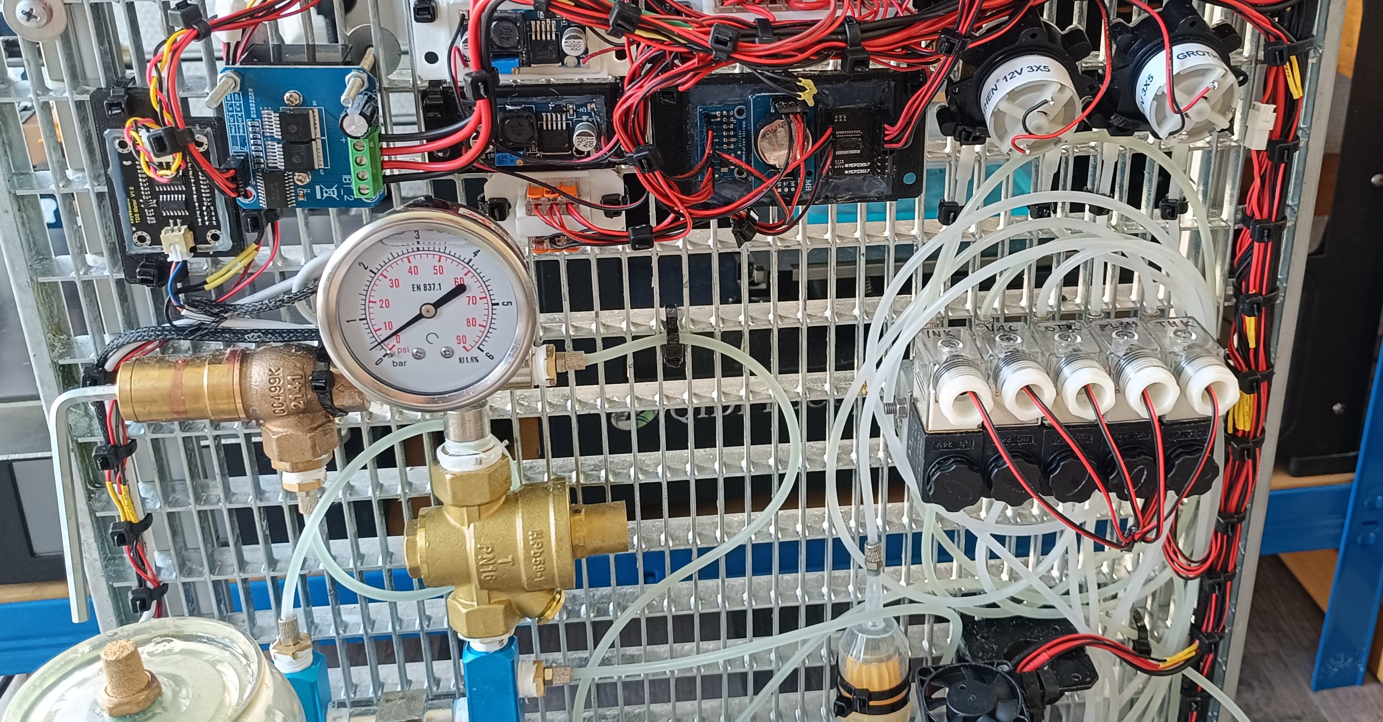
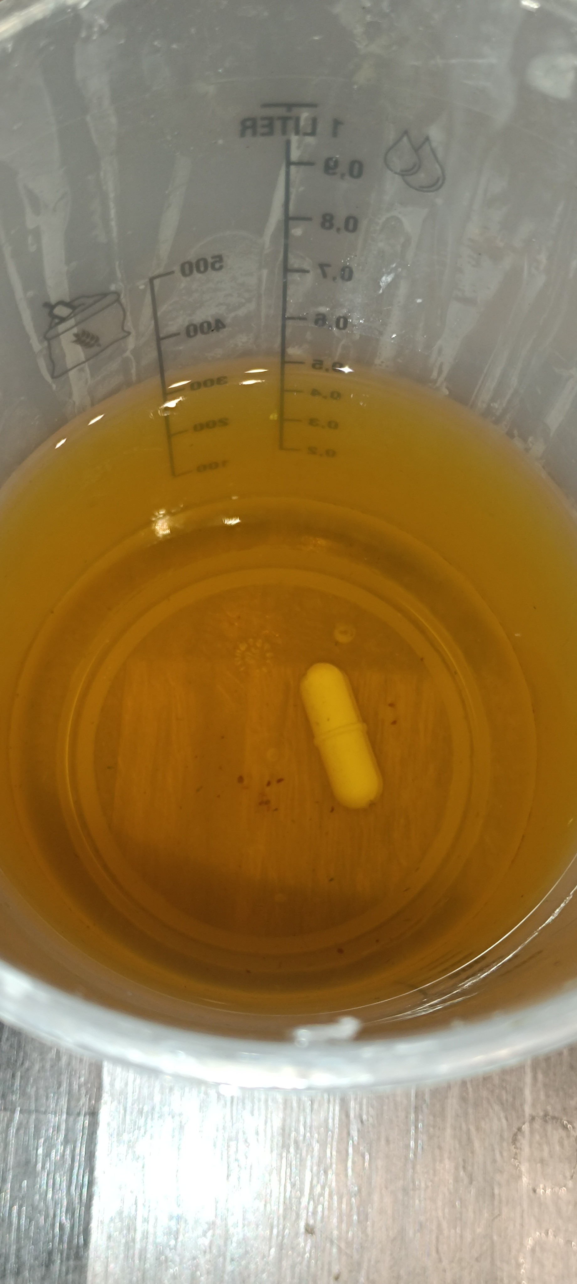
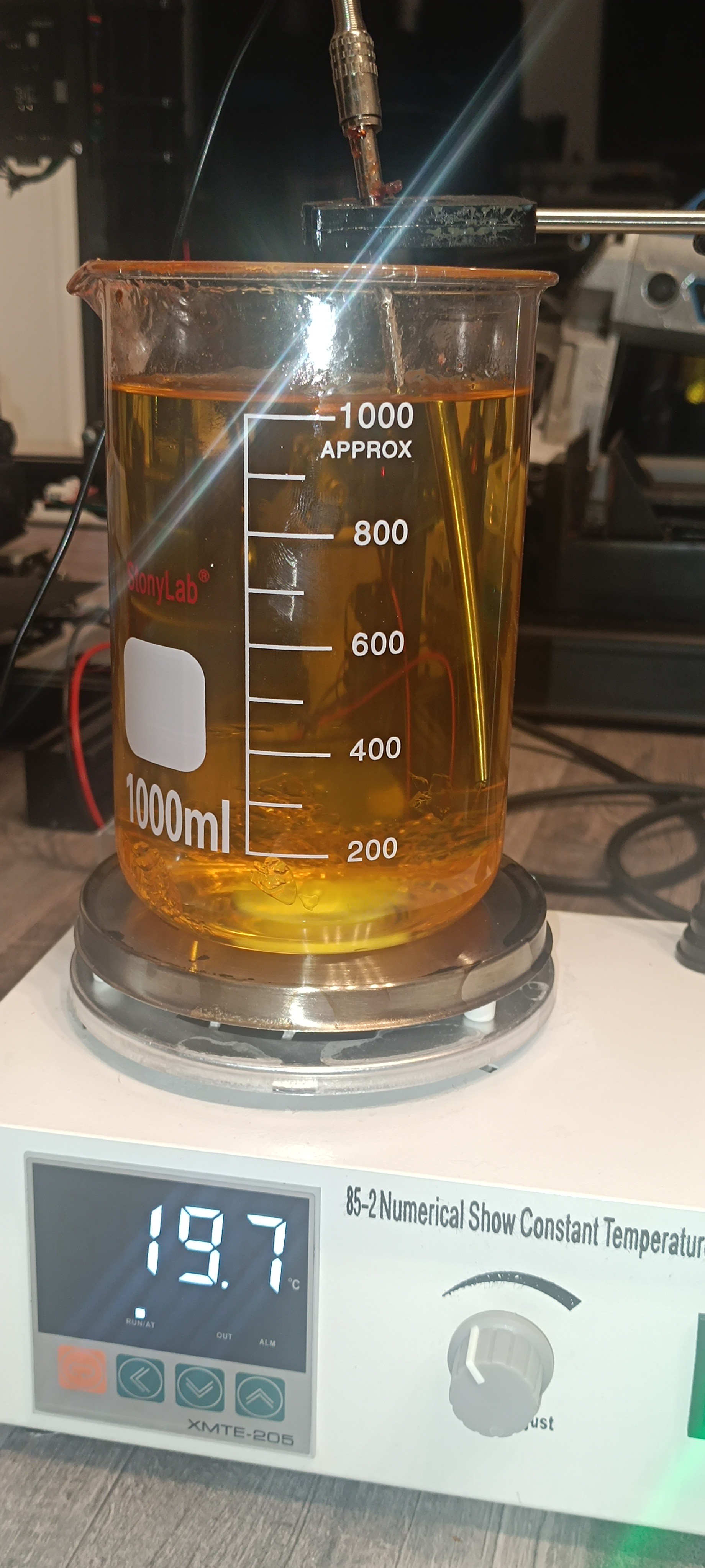
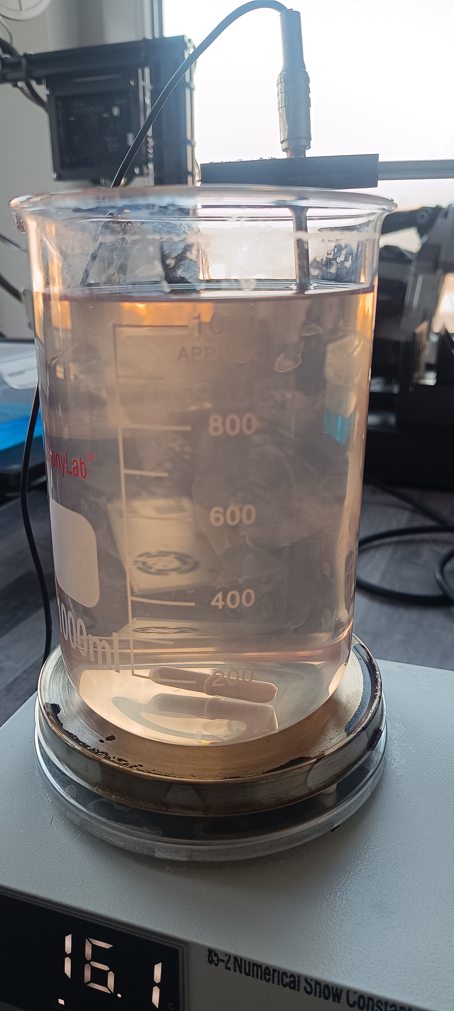
From the ink mixing chamber the ink gets transfered to a viscosity measuring cylinder by a pneumatic rubber pump. The ink cylinder is pressurized and connected to the nozzle which has a valve that stays closed until it reaches a certain pressure to prevent the ink from dripping from the nozzle when not under the right pressure. The pneumatic driven rubber pump is driven with 1 bar above set ink pressure to be able to pump the ink into the cylinder through an ink filter. The pump also has check valves at the in and outlet.
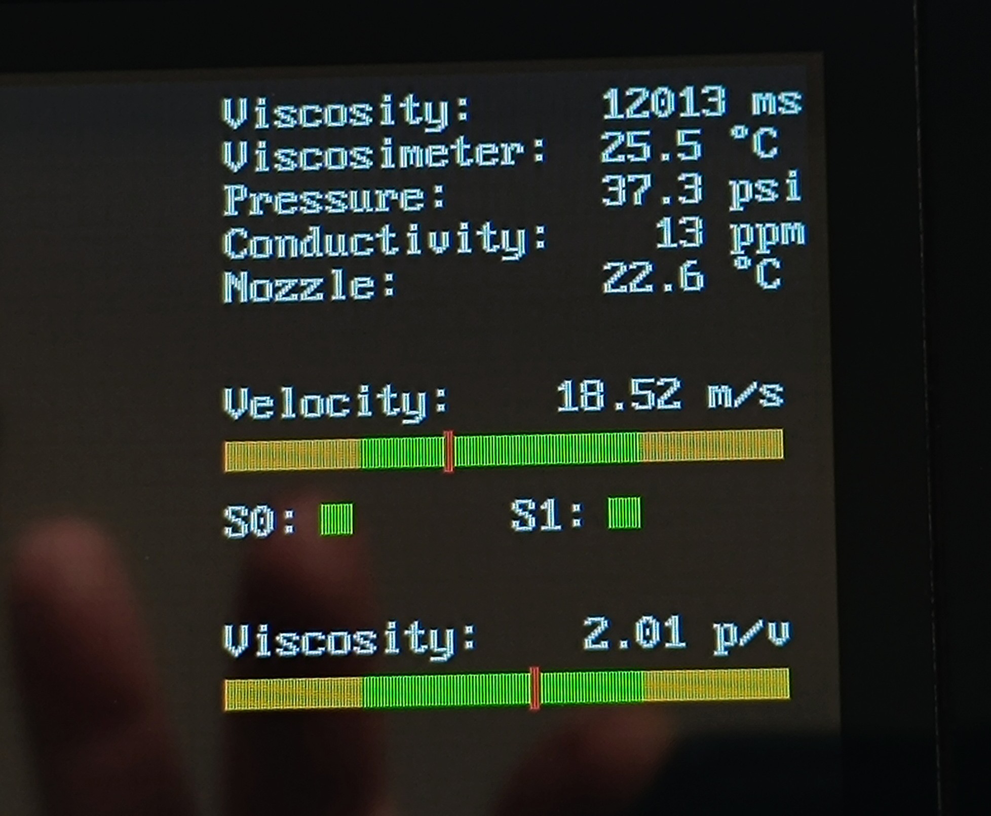
The cylinder has a floating magnet in it and multiple reed switches to detect the ink level. For measuring the viscosity the printer measures the time that it takes to empty the cylinder and according to the set flow time the printer adds ink or make up to the ink chamber - or nothing if everything fits and the ink level in the ink mixing chamber is high enough (it also has a floating magnet and reed switches). The viscosity is measured to get the same print quality at all times during operation.
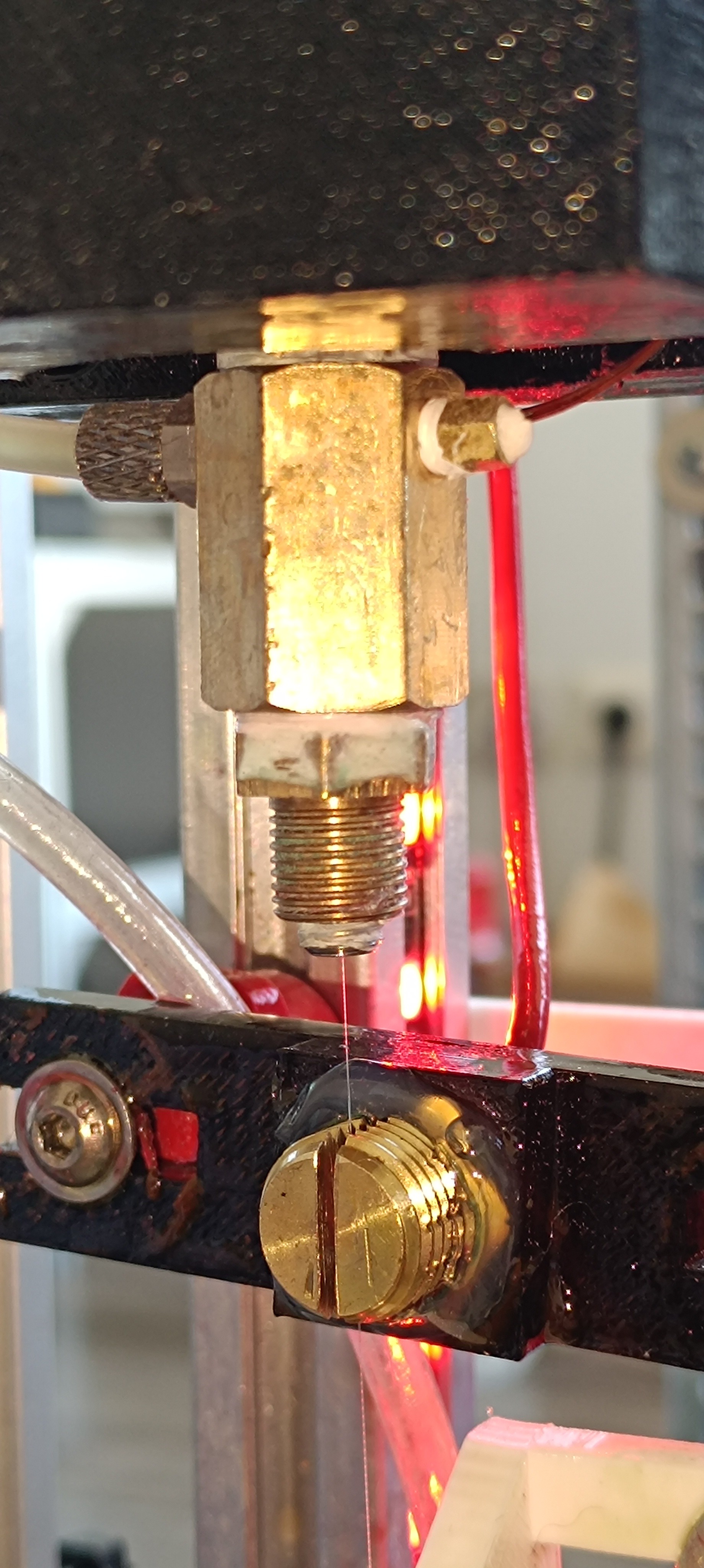
The next step in the cycle is the printhead.
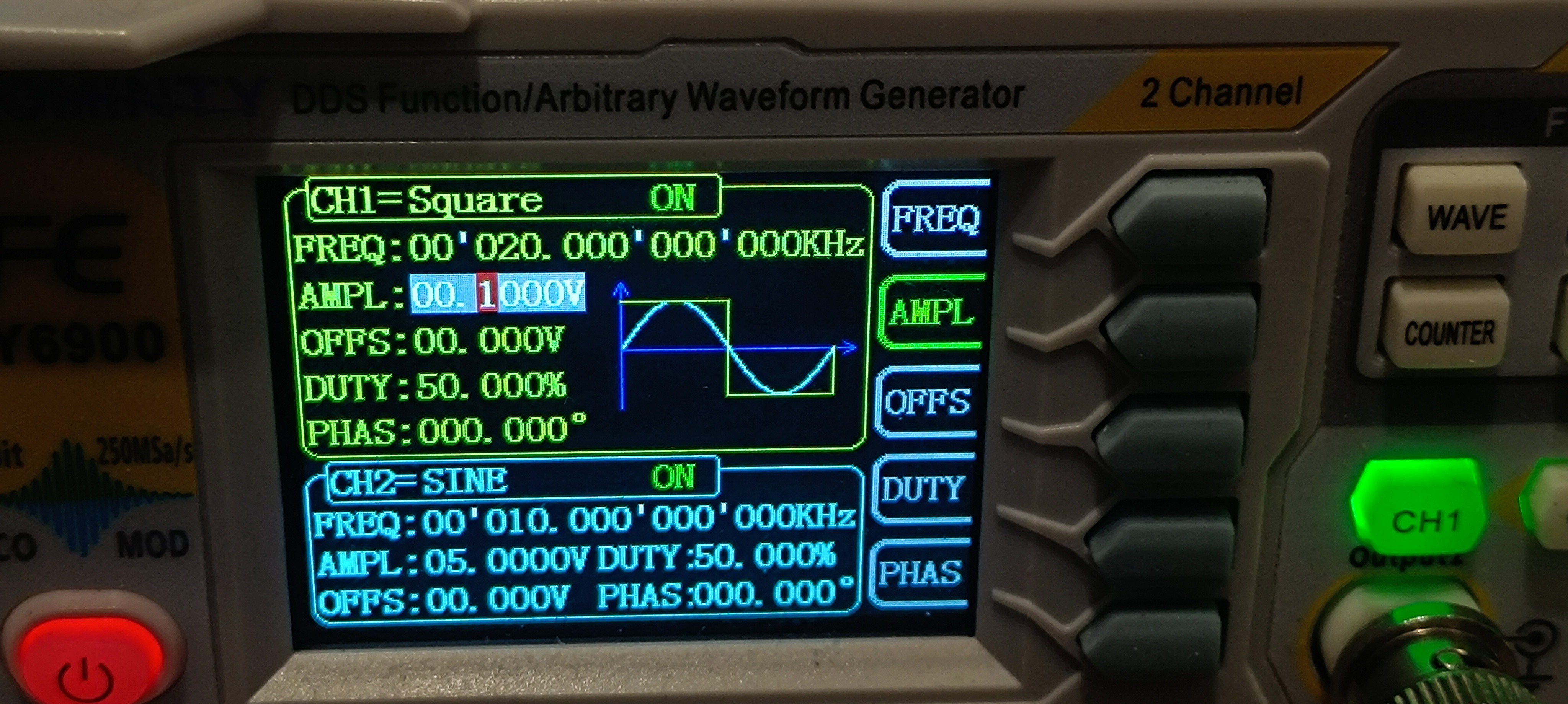
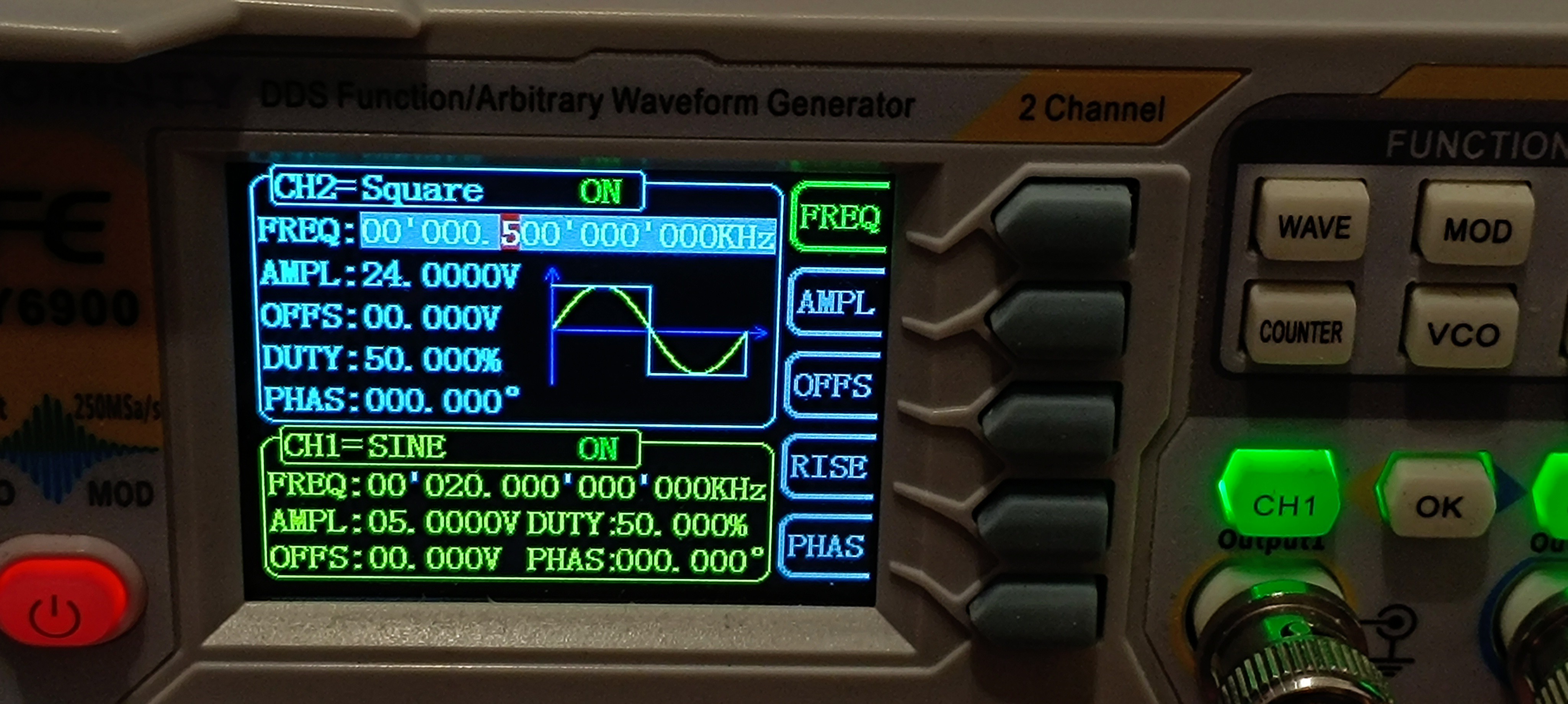
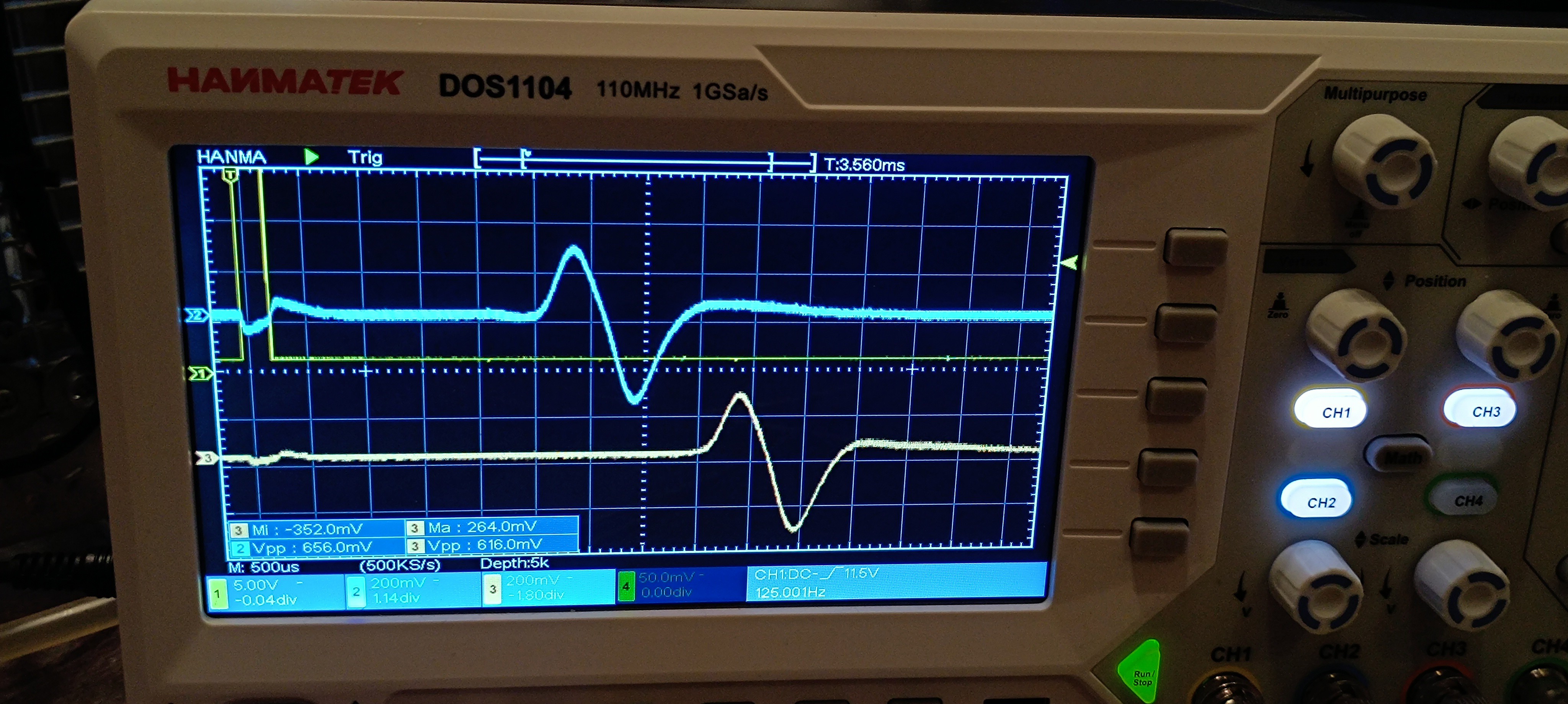
The "low pressure limit valve" at the printhead is connected to the nozzle which contains a piezo crystal that is driven with a frequency that breaks the ink stream up into dropplets using the Plateau–Rayleigh Instability.
After the nozzle there follows a tunnel that is driven by a high voltage to charge the dropplet and after this there follows a high voltage deflection plate to kick dropplets out of the stream to form pattern on the printed surface.
The unused ink streams right into an ink return block which is connected to a sensor that prooves whether the charging has worked and from there it get sucked back into the ink mixing chamber by vacuum to close the cycle.
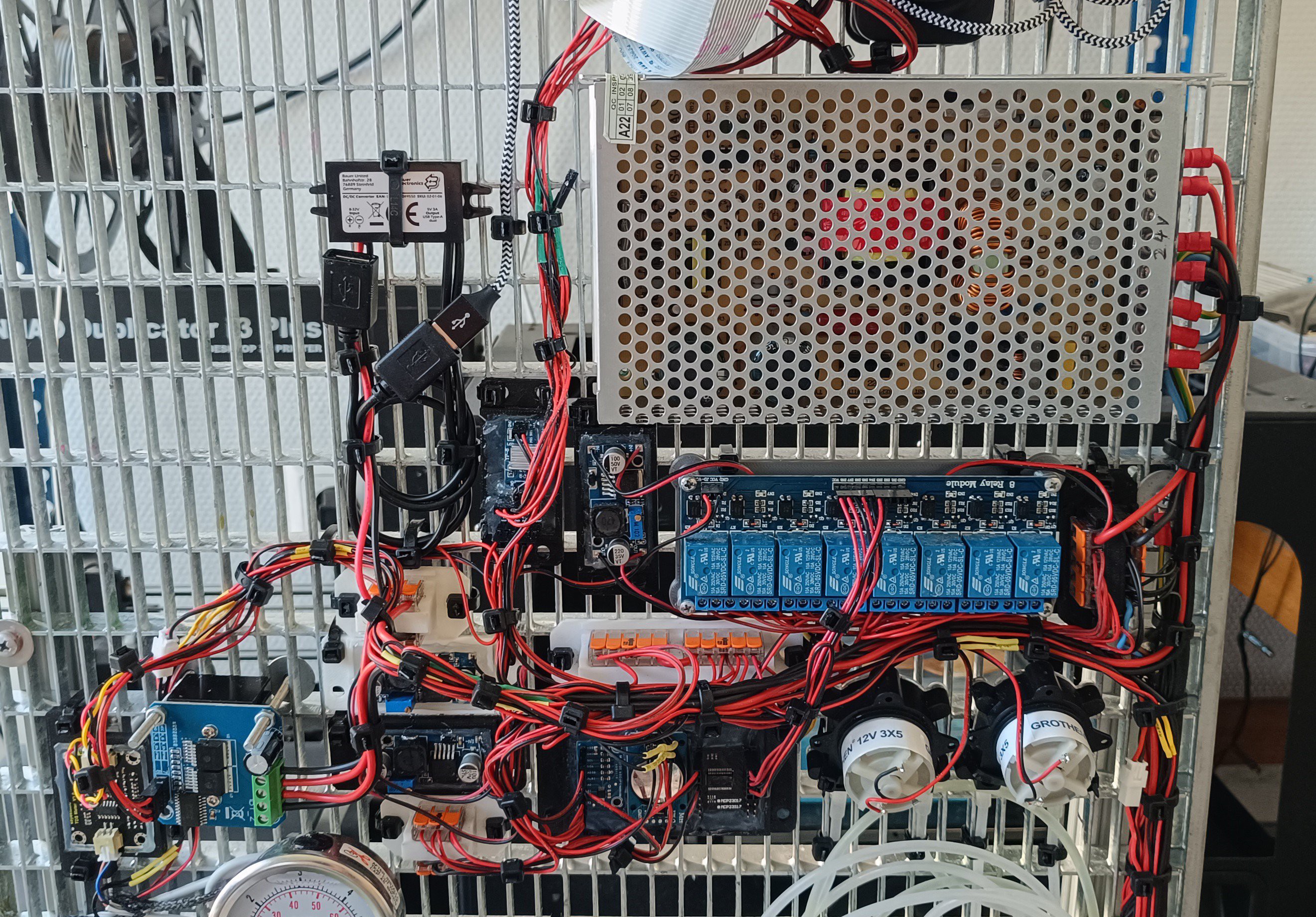
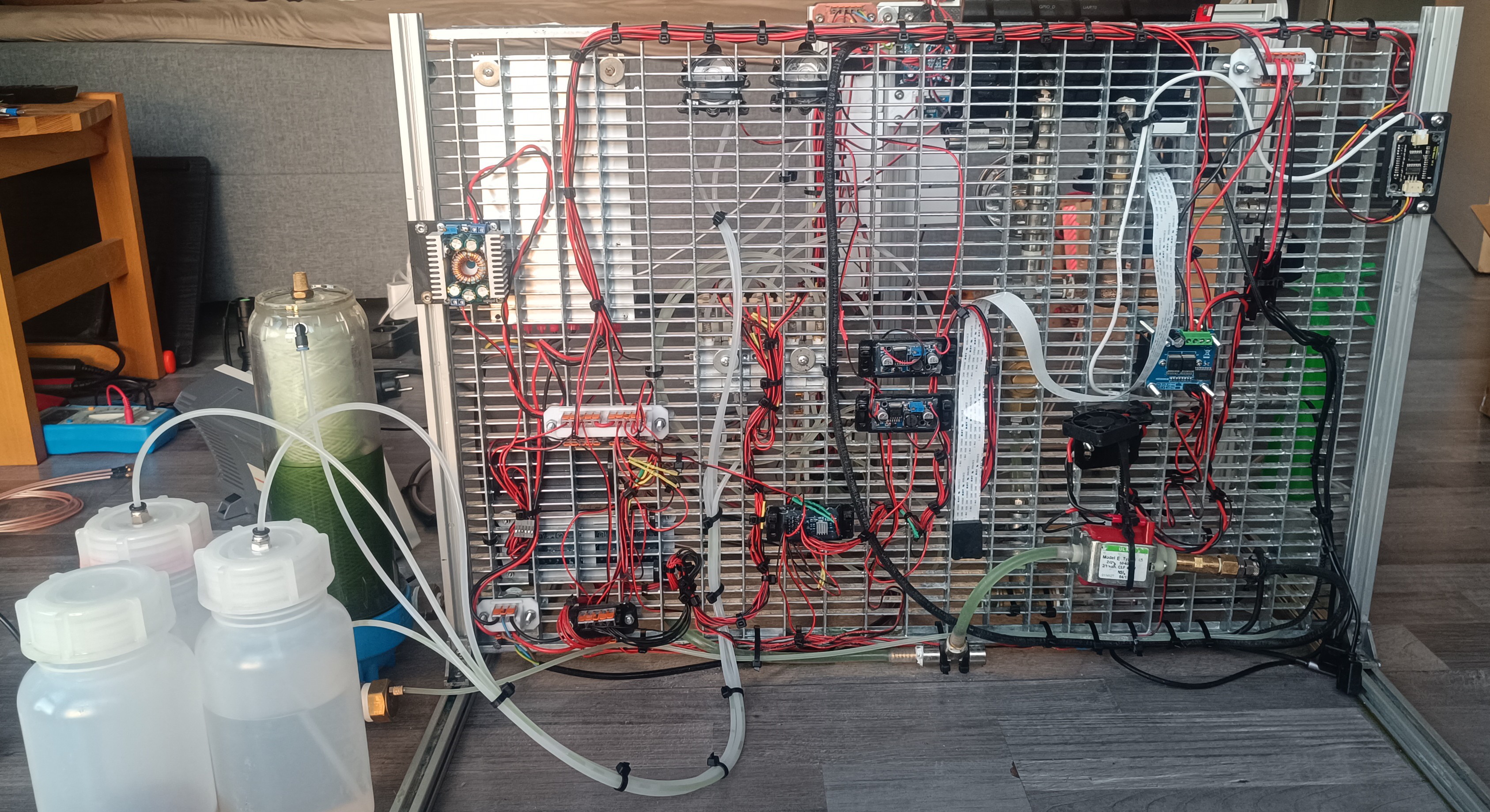
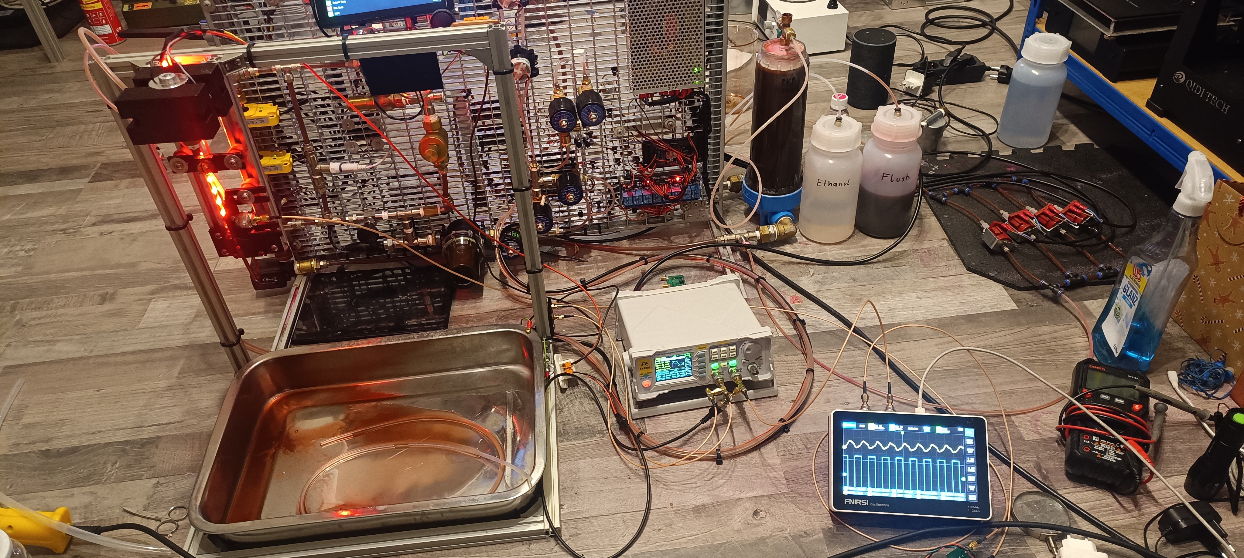
I think the pneumatics, hydraulics and their control circuits are quite simple and would not be very complicated to build for an open source system.
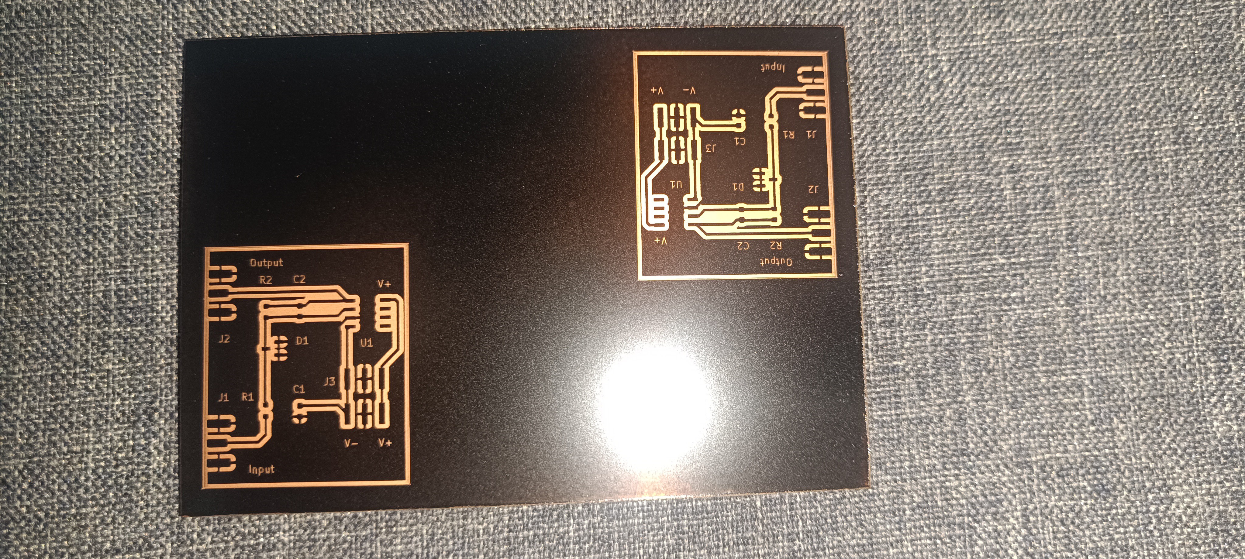
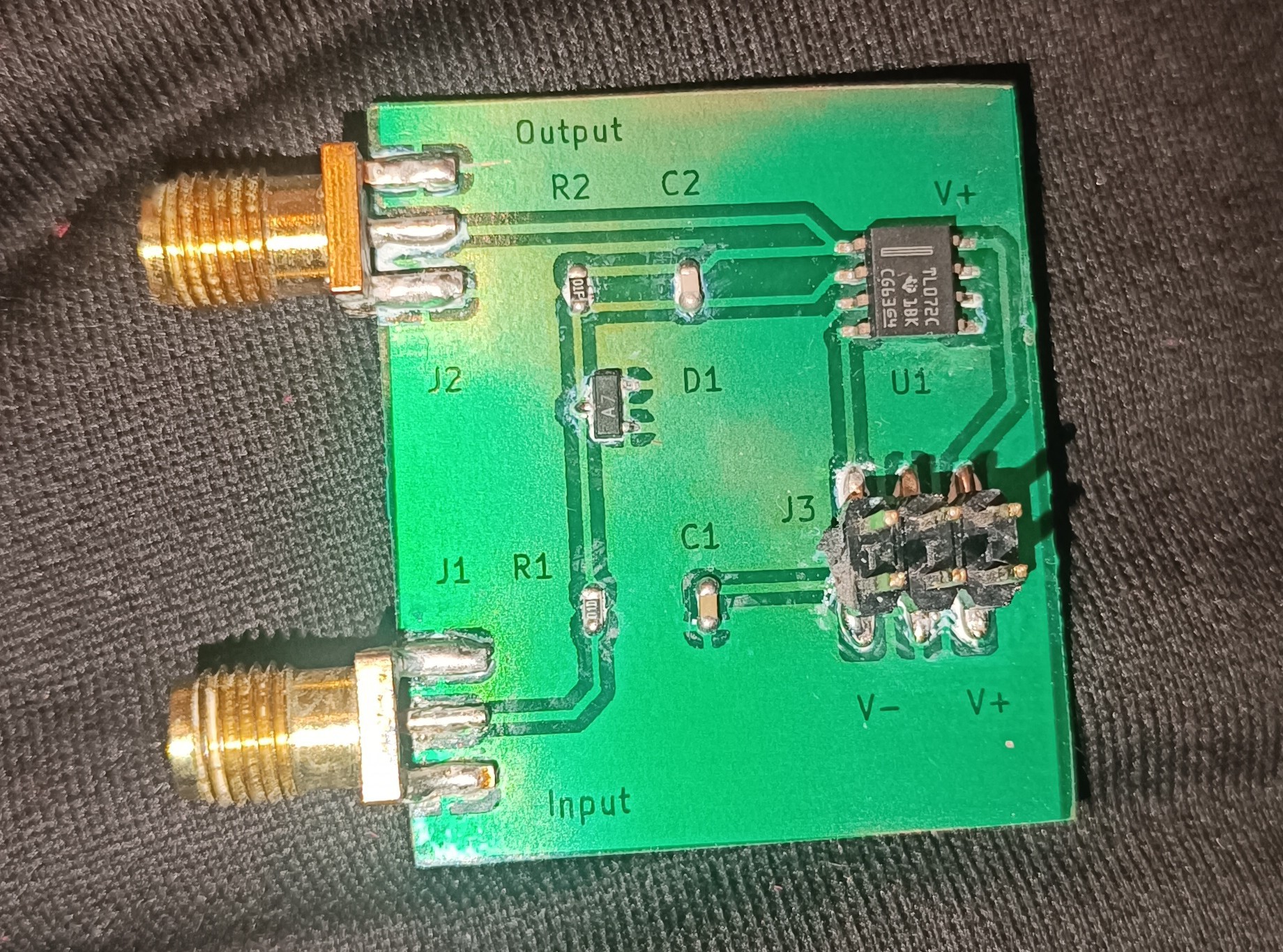
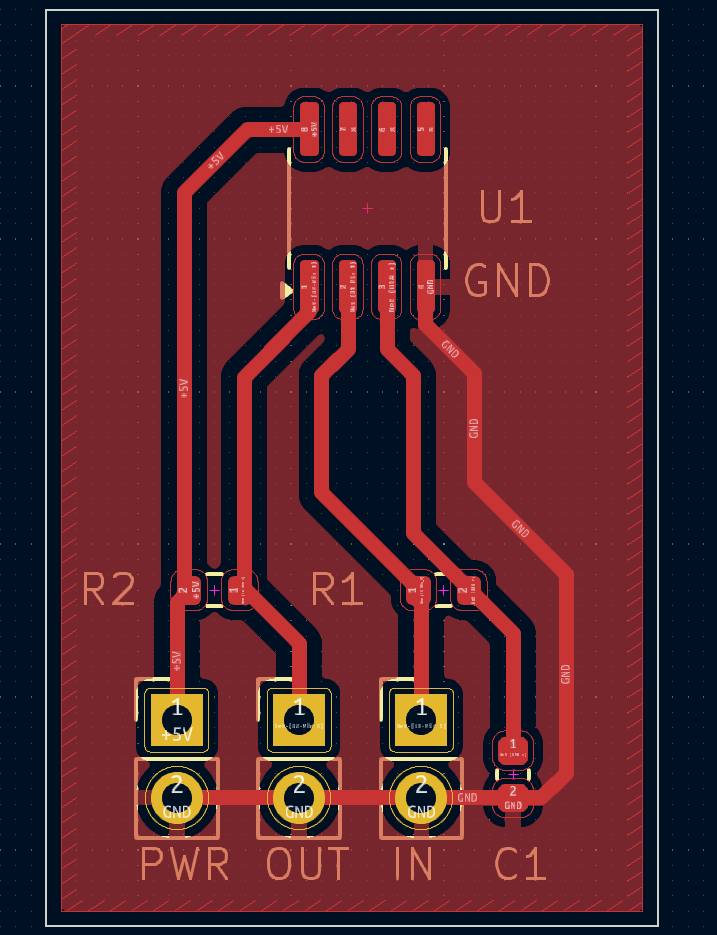
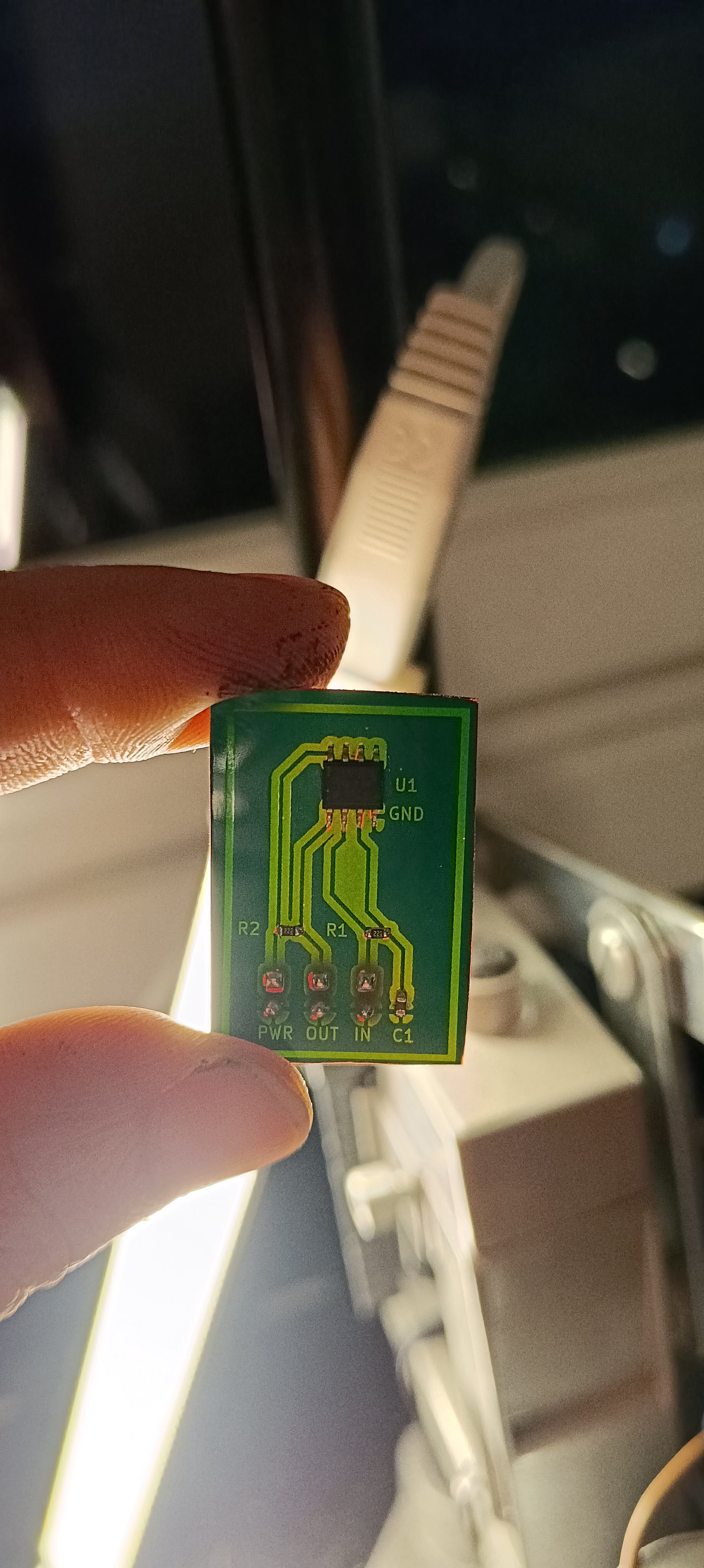
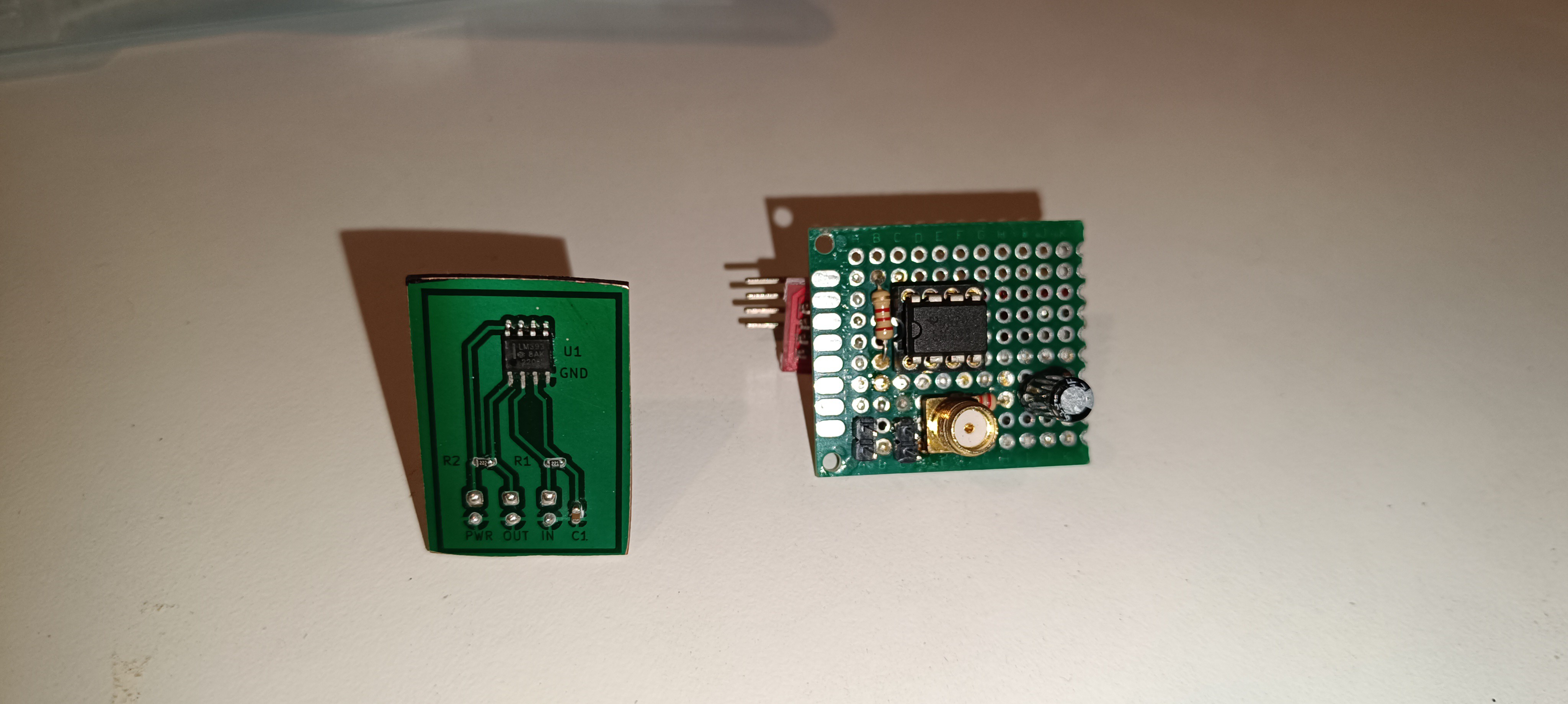
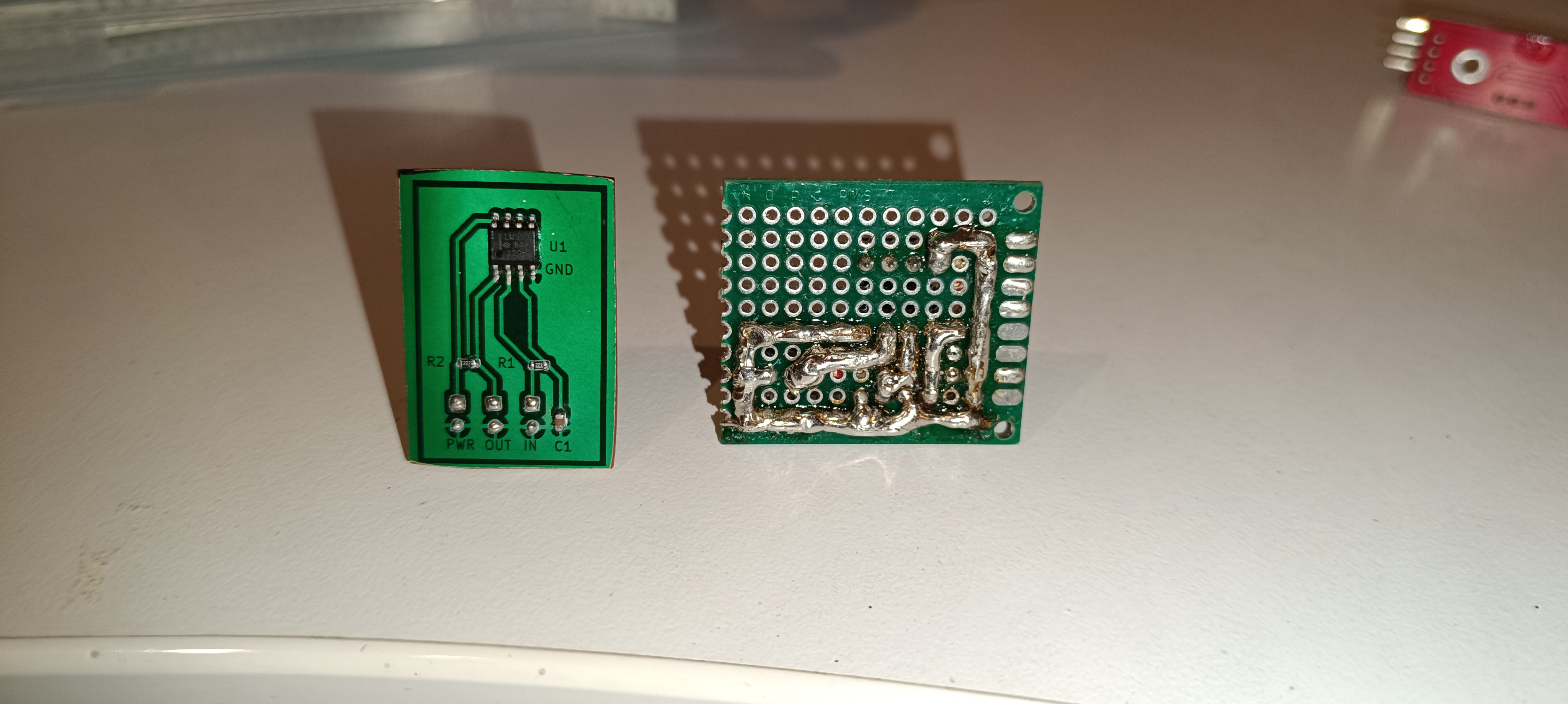
The electrical control of the printhead at the other hand, like the nozzle piezo drive, charging, deflection and sensing signal are more complicated,...
Read more »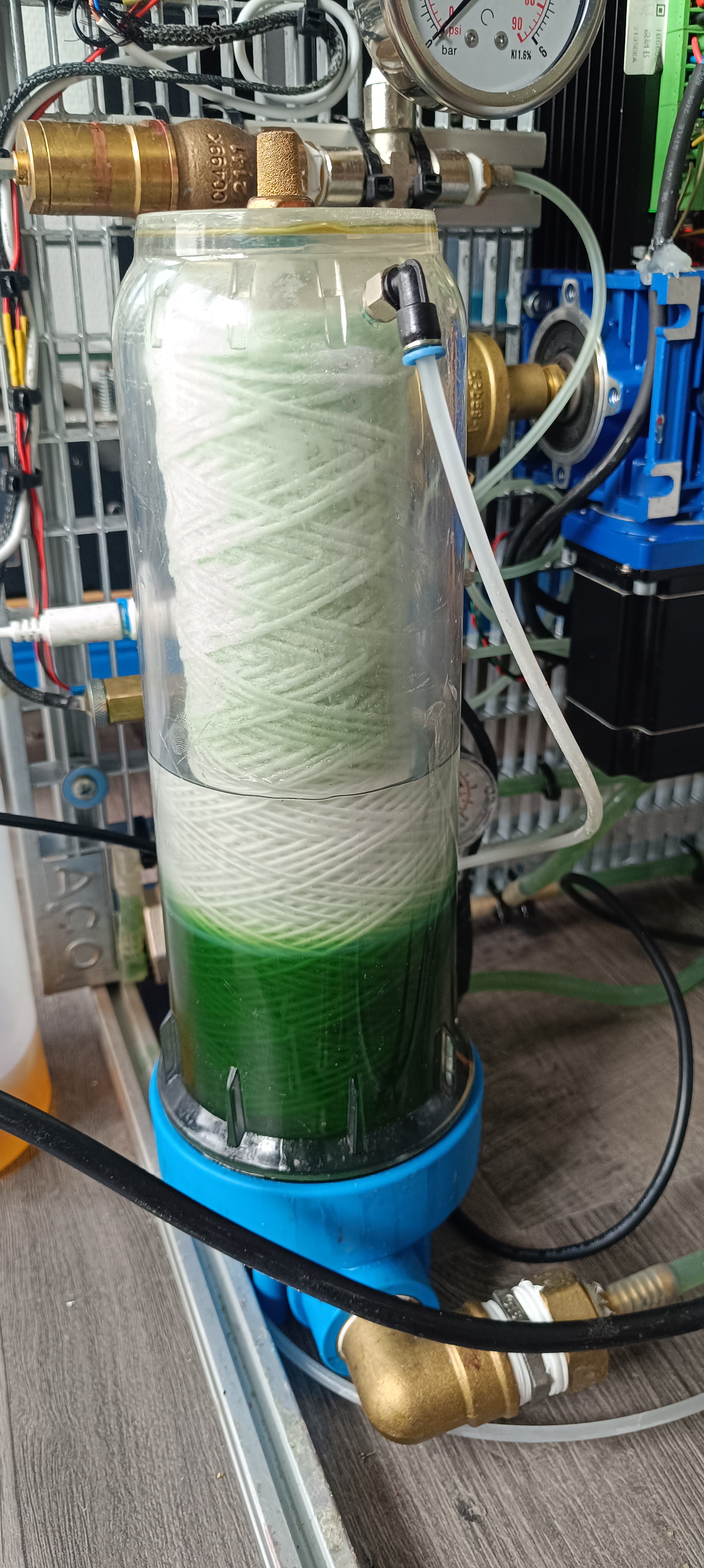


 touchaddict
 Ricardo Ferro
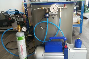
this project is amazing !