-
[T] Tetrinsic Taic: Solar panel variant
04/21/2023 at 01:35 • 0 commentsI was looking at the nice little solar cell built into my calculator, and thought of something: for the people that would say "I'd (almost) never turn those LCDs on", what if a different surface could still have a use compared to a inert slab of material? Instead of turning power into photons, there could be an opportunity to turn photons into power. Were in the 2020s now and should be thinking about how to integrate sustainable power into products. There actually are some solar keyboards, but it's the first time I'm ever hearing about them and the keys themselves sure aren't photovoltaics.
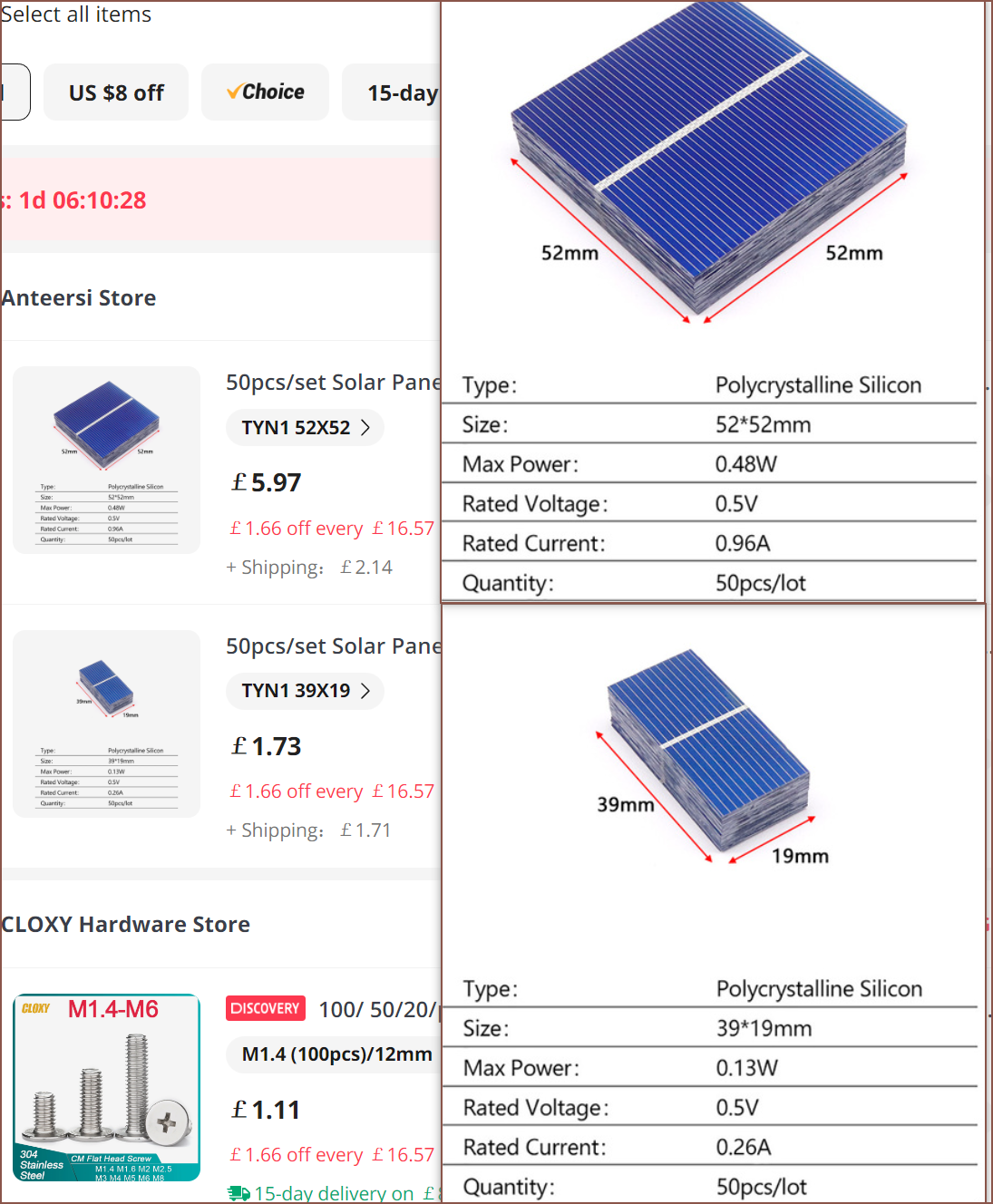
Supringingly, conveniently enough, there are 2 solar cells that are size equivalent to the LCDs on Tetrinsic and Tetent:
These kinds of solar cells are bottom-dollar cheap but the downsides are that they're quite fragile and you seeminlgly need to solder on tabs for the annode and cathode. Those silver looking lines are actually wires for the cathode. Ideally, the panels can be optically glued to a custom 1mm pane of glass.
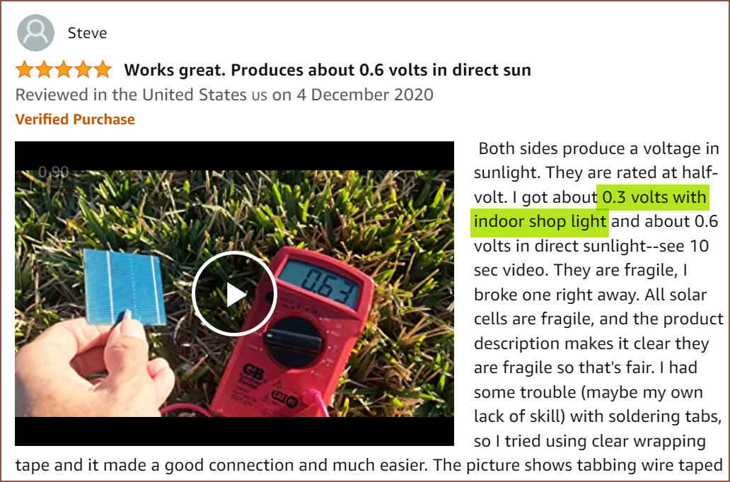
I found this Amazon review that gives some useful metrics on the performance of these kinds of cells:
As the individual panels are likely to receive different amount of light intensity, they should be connected in parallel. If they're connected in series and one panel is completely covered, all power generation gets cut.
Assuming that one 52x52 cell = 4 39x19 cells, I'll assume that:
Indoor current, normalised to 3.7V (nominal LiPo battery voltage):
60% * 3 * 480mW / 3.7V = 233mA
This seems like a decent amount of power, even if it was actually something like 180mA in practice. I also wonder if the cell could be cleanly broken off to get 36mm (length of LCD), but designing for 39mm should be perfectly fine as is (and cuts down the amount of manufacturing steps / things that can go wrong)
Without the LCD screens, the only thing that would really use a chunk of power are the BLDC motors (and the speaker). I was considering using some small haptic motors in a bid to have something even lower power, but they still require a driver controller so I decided to skip on it. I feel like the larger BLDC would be able to create a stronger force for the same power anyway (since it has a larger diameter), but I wonder if a low-power-consuming vibration could overcome the inertia of the motor and slack in the chain.
Along with the 10Ah battery planned for Tetent, hopefully this could mean that if typing is the only thing a user needs and detent strength is kept low, the Tetent Taic would need to be charged as often as the Casio Classwhiz I've owned for 6 years:
0 times.
-
[EM] Created BMI160 footprint
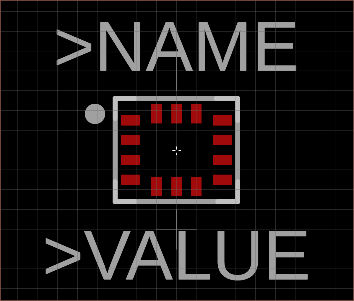
04/19/2023 at 19:40 • 0 commentsThis should've been effortless, not tedious. For some reason, there's no auto generator for LGA packages. There's also no such thing as the dimension tool in the world of footprint generation, and instead, the positions of the pins had to be manually calculated.
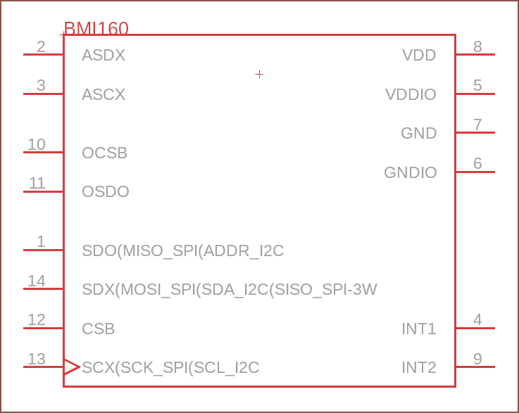
Oh, and I did try to get away with just importing the symbol into the schematic, but Fusion declined, saying I needed a footprint first.
I copied the document things from the ADC footprint to try and retain consistency.
When is an AI that takes in a schematic input and produces a footprint going to exist? Doc drawings look pretty standardised... just a suggestion. Maybe even a manually coded, OCR-type thing could work.
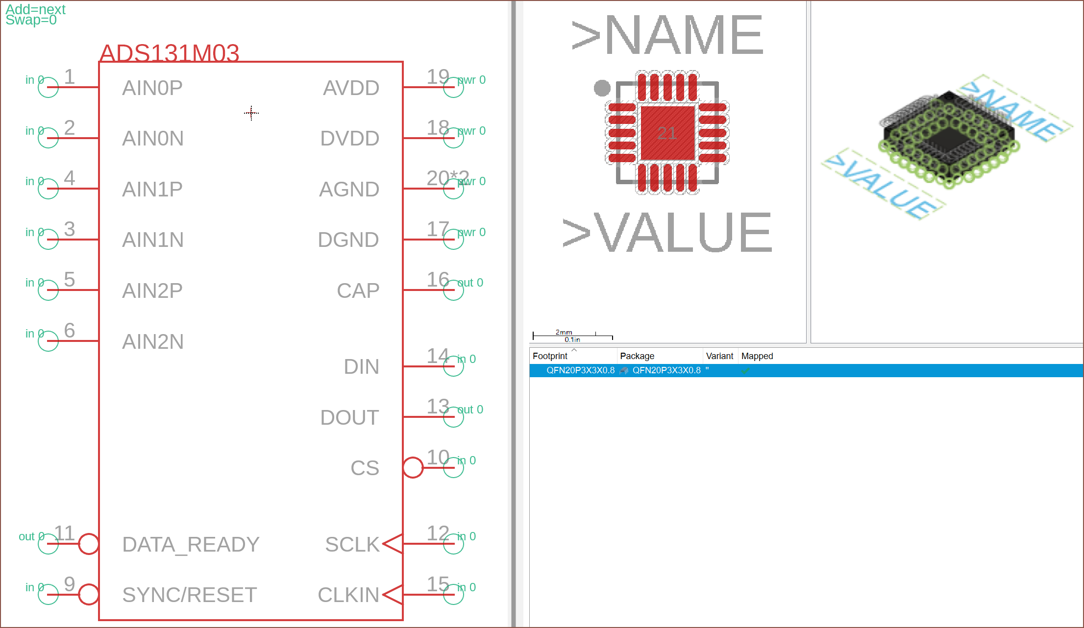
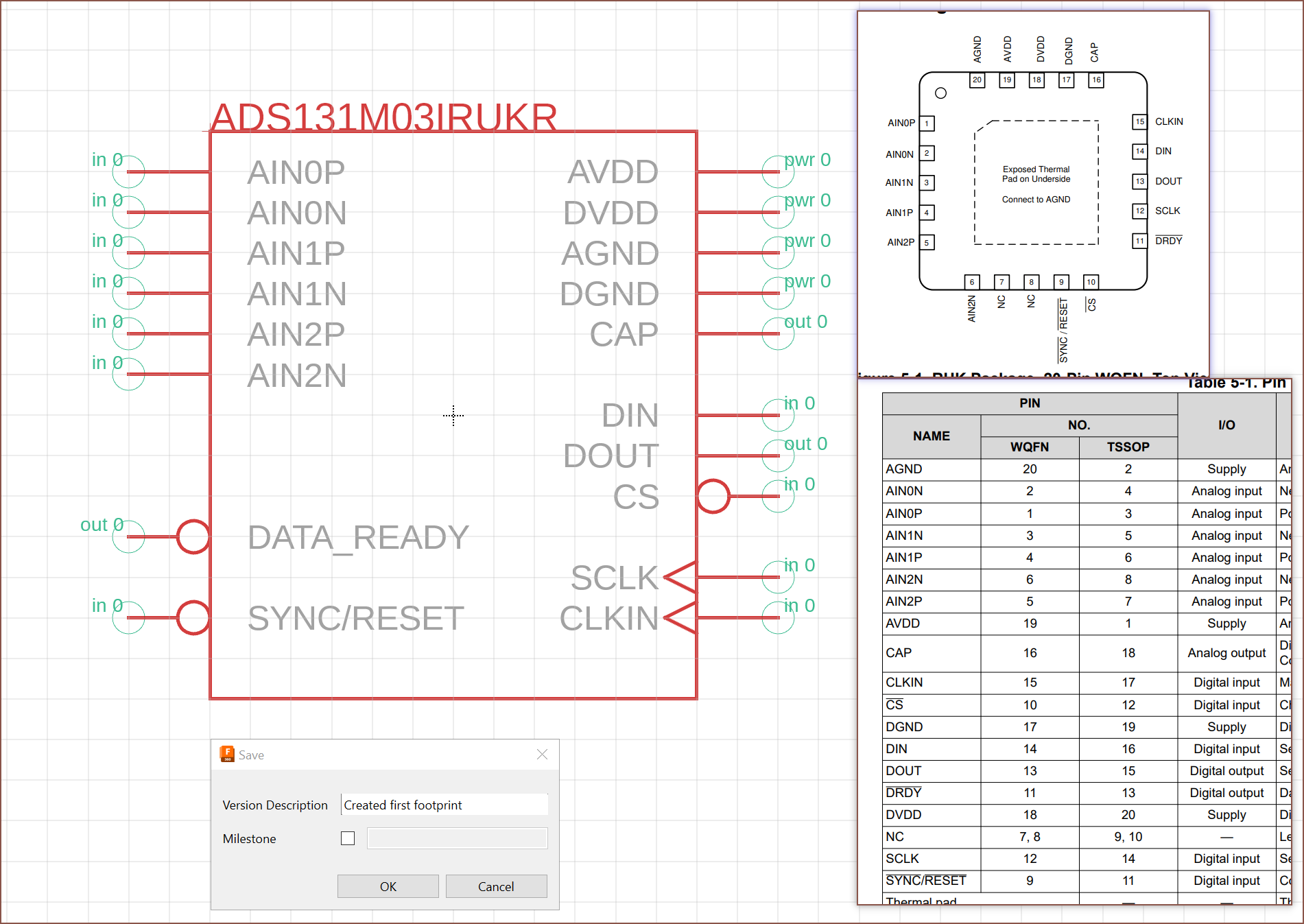
This is the symbol:
-
[EM] ADC schematic entry
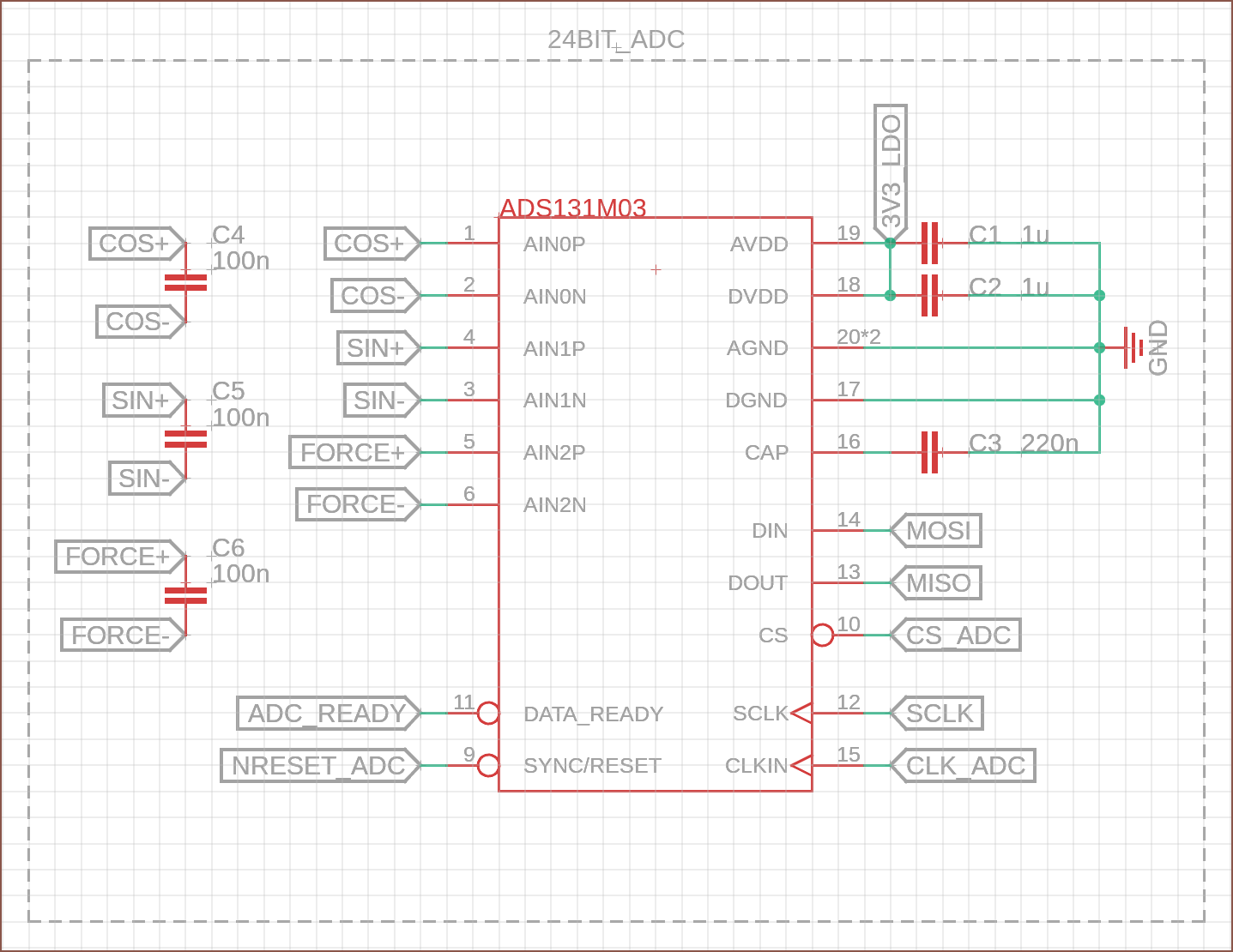
04/19/2023 at 17:58 • 0 commentsFuelled off the good vibes of the Simcity 2013 soundtrack, I've ported over the circuit from my EasyEDA schematic that relates to the ADC:
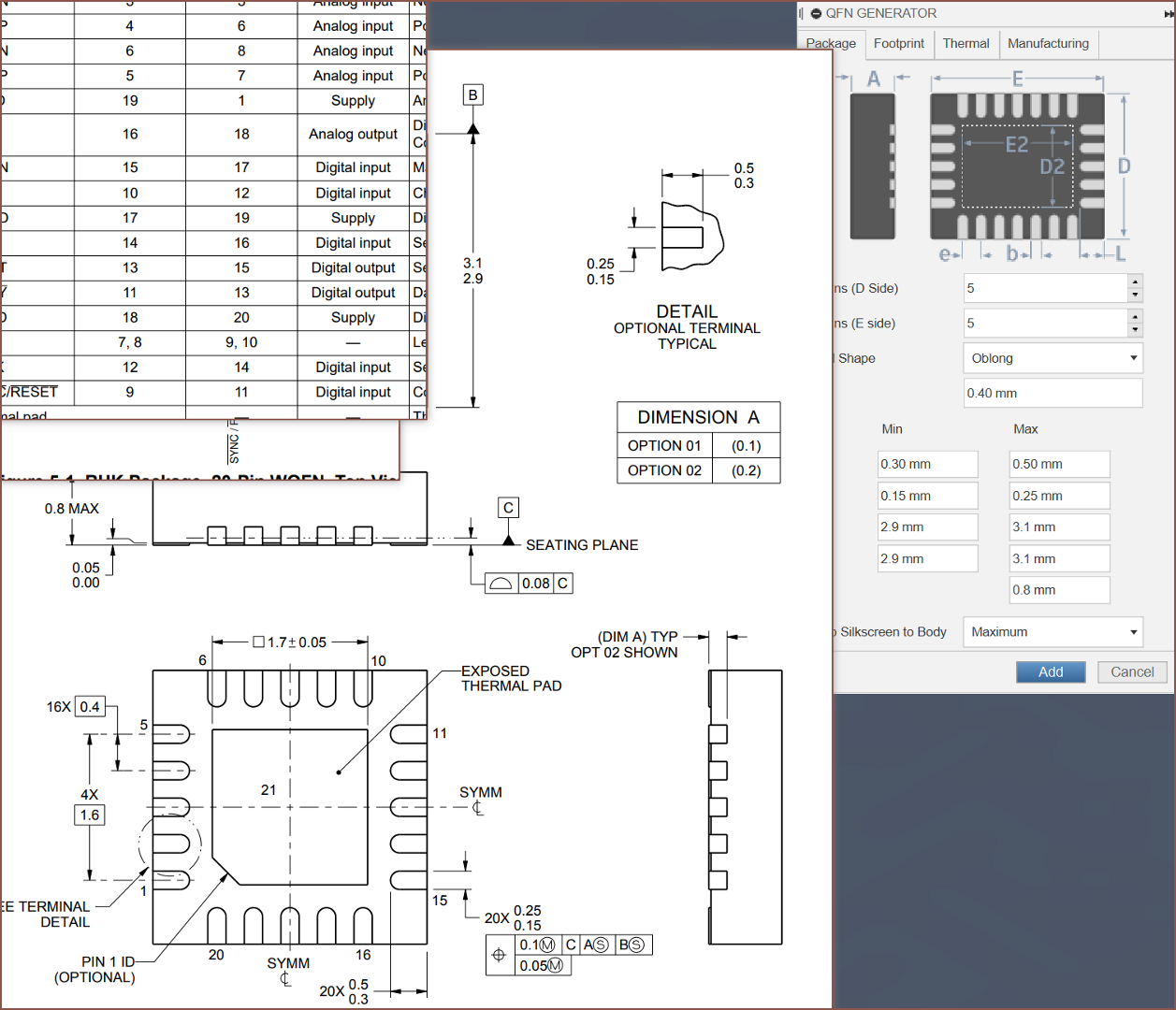
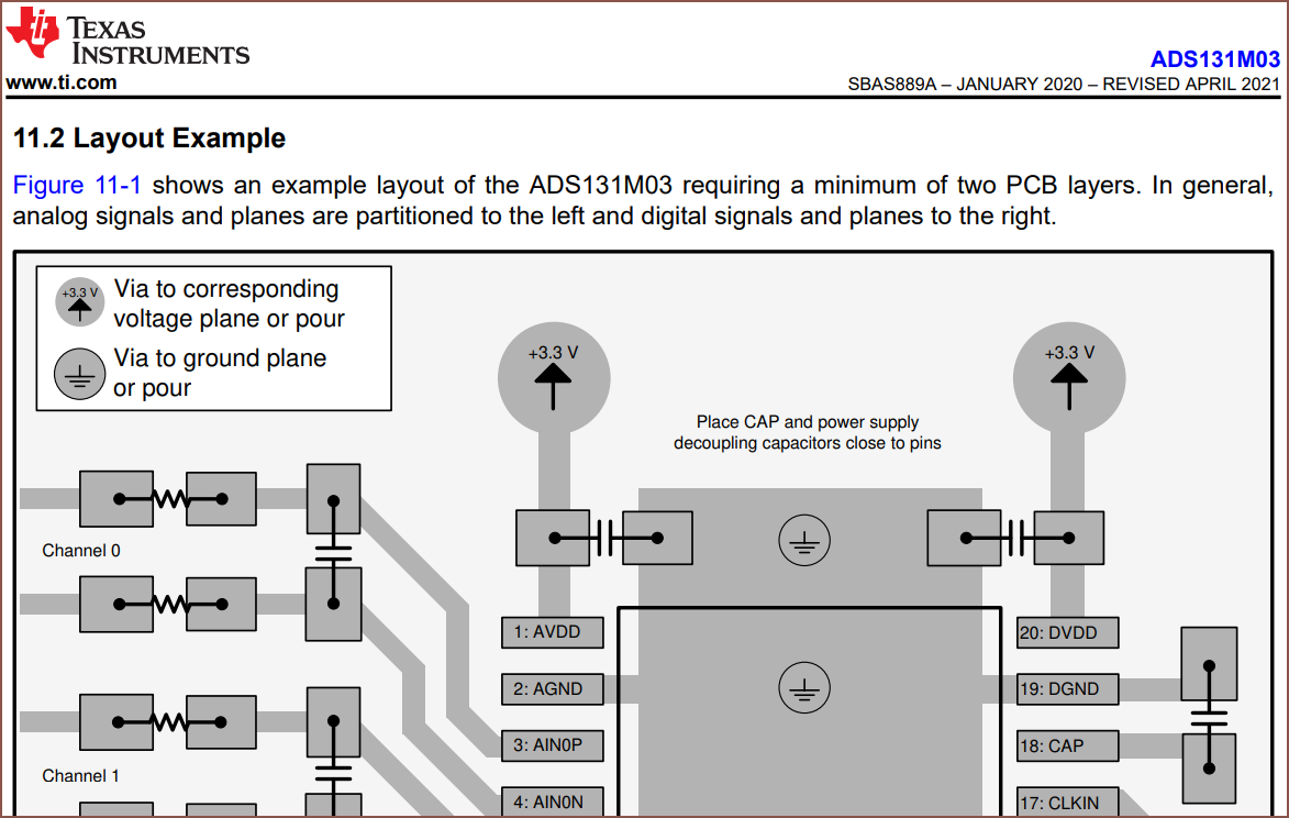
The first thing that I did was create the 3D model using the wizard, which also creates a PCB footprint along with it.
I've also found out that the actual name for what Fusion360 calls a slot and what Apple calls a Dynamic Island is a shape called an "oblong". As you can also see, I increased the spacing of the pins. This is because it's needlessly time consuming to fix the formatting of components added to the pins because those small +'s overlap with everything:
Speaking of the +, I've moved the IC symbol's one closer to the top so that I don't have to figure out the perfect center for every IC, especially as they get longer.
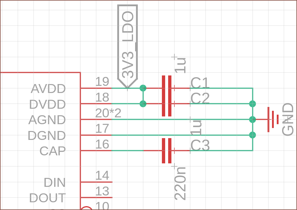
I've added more capacitors to this schematic, as recommended by the datasheet. The capacitor between the + and - signal was also present in the cheap scale I tore down, so it's probably needed. I'm going with a seemingly low capacitance value as I'm assuming that a higher one will take longer to react to changes.
-
[EM] First symbol in Fusion360 Electronics
04/19/2023 at 00:48 • 0 comments[EM] = Electronic Modelling
So, probably 2 hours after deciding that it's probably time to start working on the PCB, I've got my first symbol.
Some things I've learned:
- While asked many times on the forum, the Fusion 360 team has no desire to implement KiCAD library imports.
- Apparently, this is something holding back users that want to create custom keyboards.
- Speaking of custom keyboards, I looked online for a split keyboard (to compare with the Lets Split I built for £81 and barely used) and everything is usually bland-looking and either large (because of the numpad), over £100 or both.
- I guess this half explains why I've got to invent a brand new input device here, despite engineers around the world with better credentials and surely working on more complex problems seemingly content with being landlocked to a desk, potentially with some pay2play tweaks (as seen on r/mk or r/ergomk). It seems that there's just not many companies in this input device business, and innovation from established players seems to be non-existent.
- Apparently, this is something holding back users that want to create custom keyboards.
- There are keyboard shortcuts for adding a pin and naming it.
- There's a "Pin Array" which basically makes this entire IC symbol for you, and I didn't know about it until I was like 2/3rds into creation.
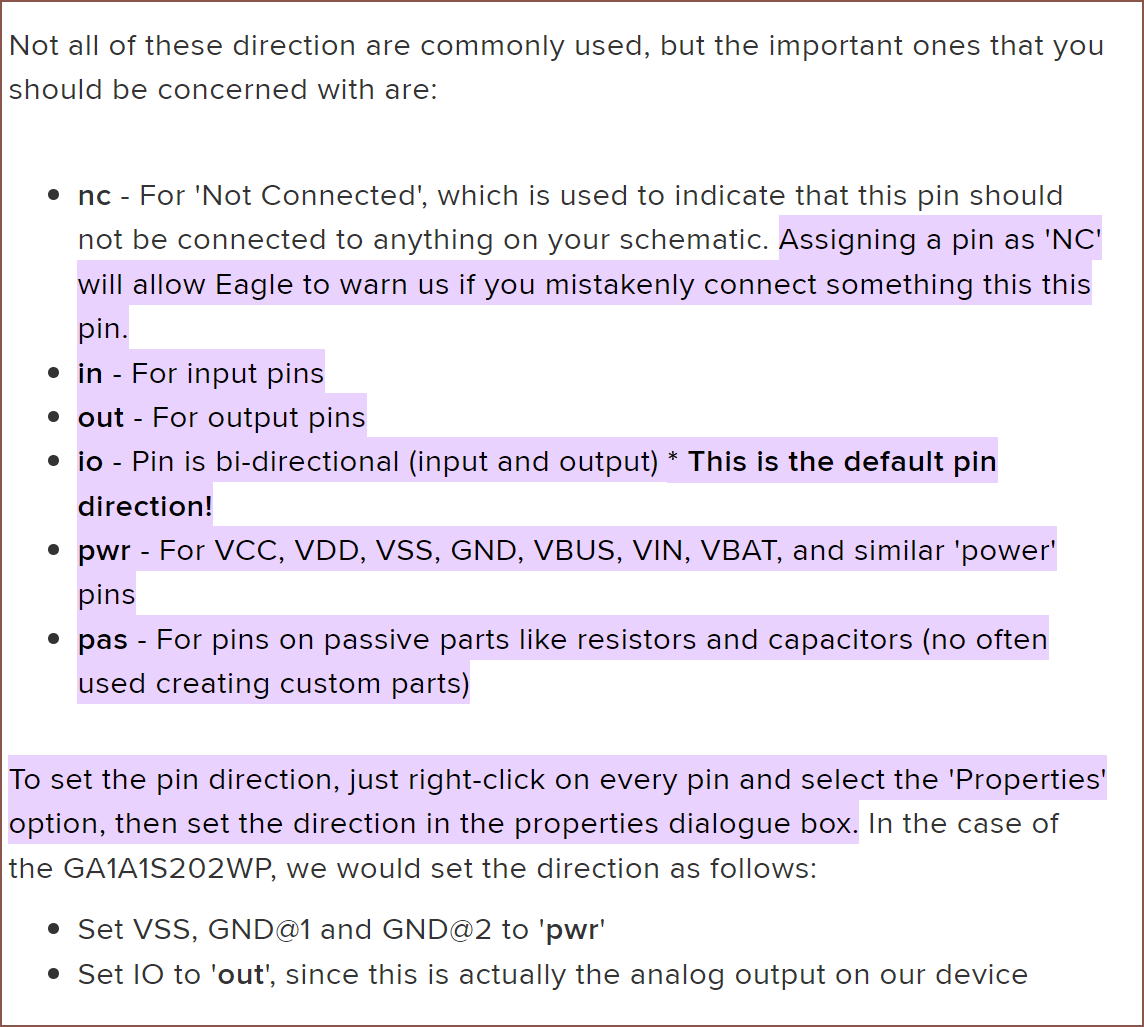
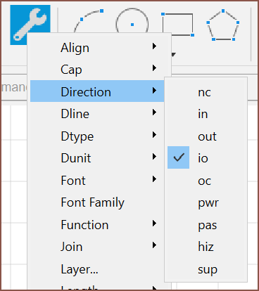
- There's some mysterious list of "Pin Directions" (see my mention of the "Change" command) and I can't find any docs on the ones that are Fusion360 exclusives (aka didn't feature in EAGLE).
- There's a "Change" comand that means that I can select what I want to change in a menu, then click on the pin I want changed.
- For example, instead of right clicking each individual pin and then clicking properties and then clicking Pin Direction and then changing "io" to "in" (because that's what I did), I can just set up the Change function and then quickly click the pins I want to change.
I can only imagine that "hiz" = High Z = high impedance. No clue what "oc" is.
Things to mention:
- I assume I can treat the components library similar to how I create a BOM folder for normal modelling.
- Next steps are to create and connect the footprint and 3D model.
- I couldn't really find any specific IC symbol layout guide to conform to, so I just tried grouping similar pins together and I think what I've created looks easy on the eyes.
- Creating this custom component first is like a low level mob fight before I go to the high level boss: the custom-footprint ESP32-S3-MINI-1U.
- (custom as in it's not a regular package like QFNXX that can be auto generated by Fusion, as well as having the most pins out of all components)
- While asked many times on the forum, the Fusion 360 team has no desire to implement KiCAD library imports.
-
[M] PCB on side?
04/16/2023 at 16:23 • 0 commentsSo I was presented a simple trade offer: +2mm of effective height for uninterrupted mounting access to the load cell screw threads. However, the drawback was the difficulty of routing out the flat flexible cables, and holding the screen.
I subscribe to the Pimaxian philosophy, so "why not both?":
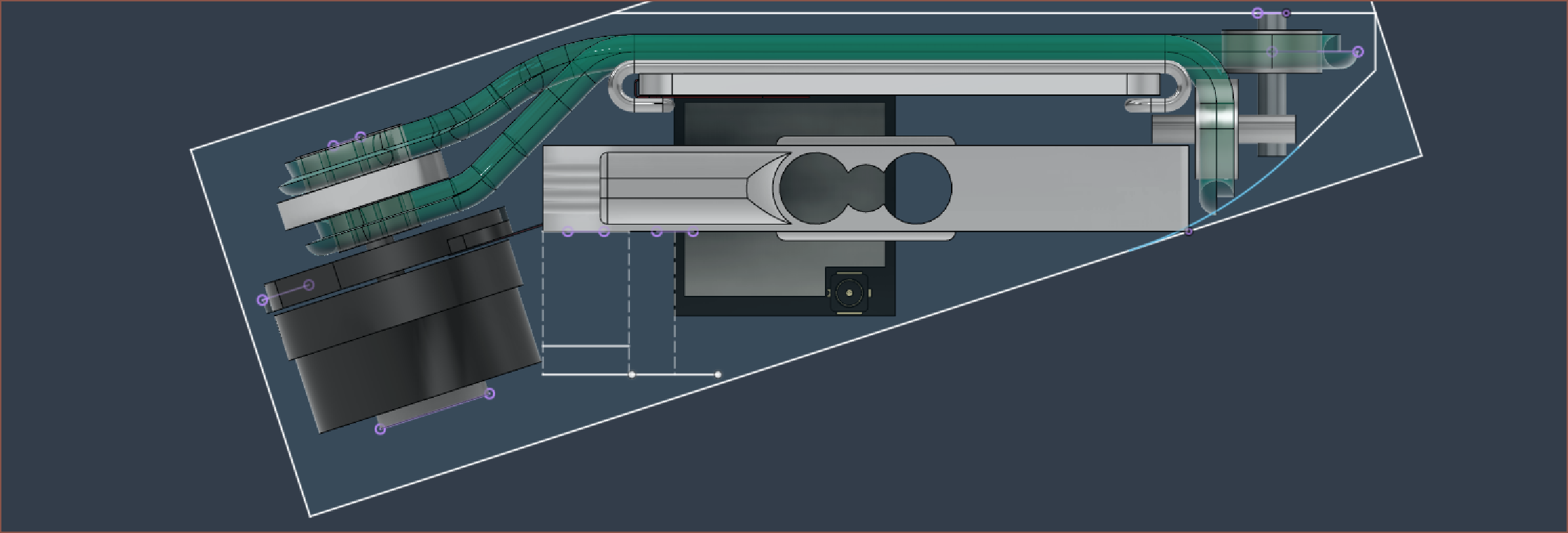
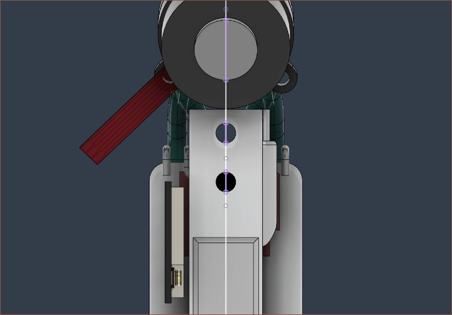
The ESP32-S3-MINI is juuuuuust about small enough to fit side-on without going out of bounds, and allows easy access to the back of the PCB, where I plan to put all the FFC and debug pads. There's also enough space for current carrying wires.
It's also quite likely that the motor's FFC can be soldered directly to the PCB.
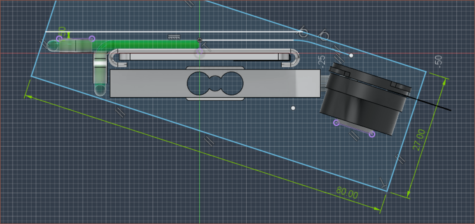
The effective height is currently about 27mm and length 80mm.
-
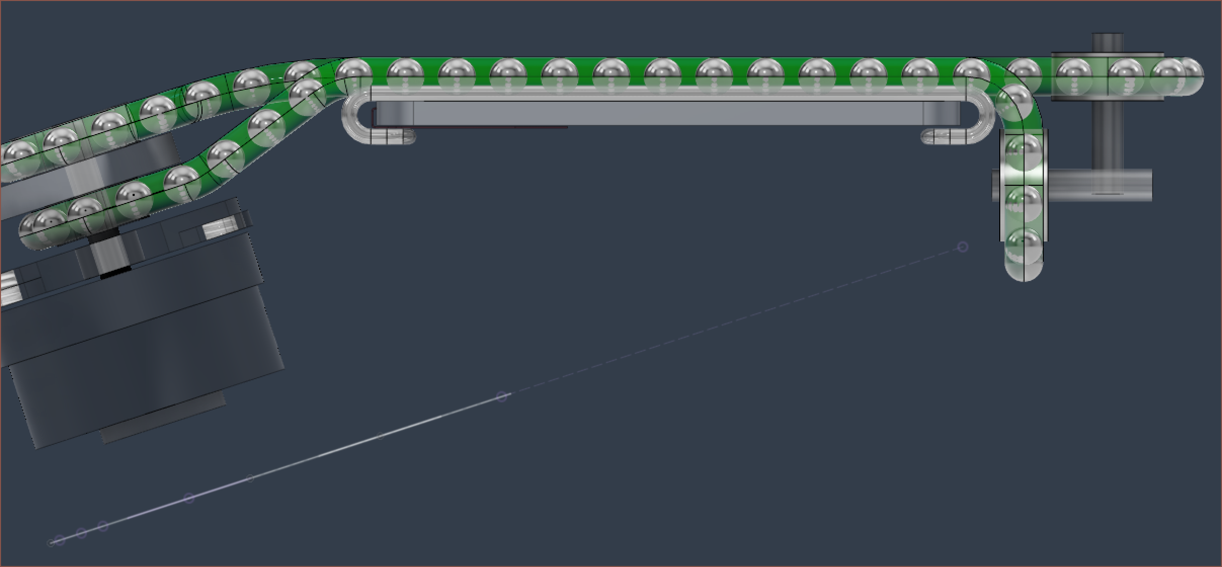
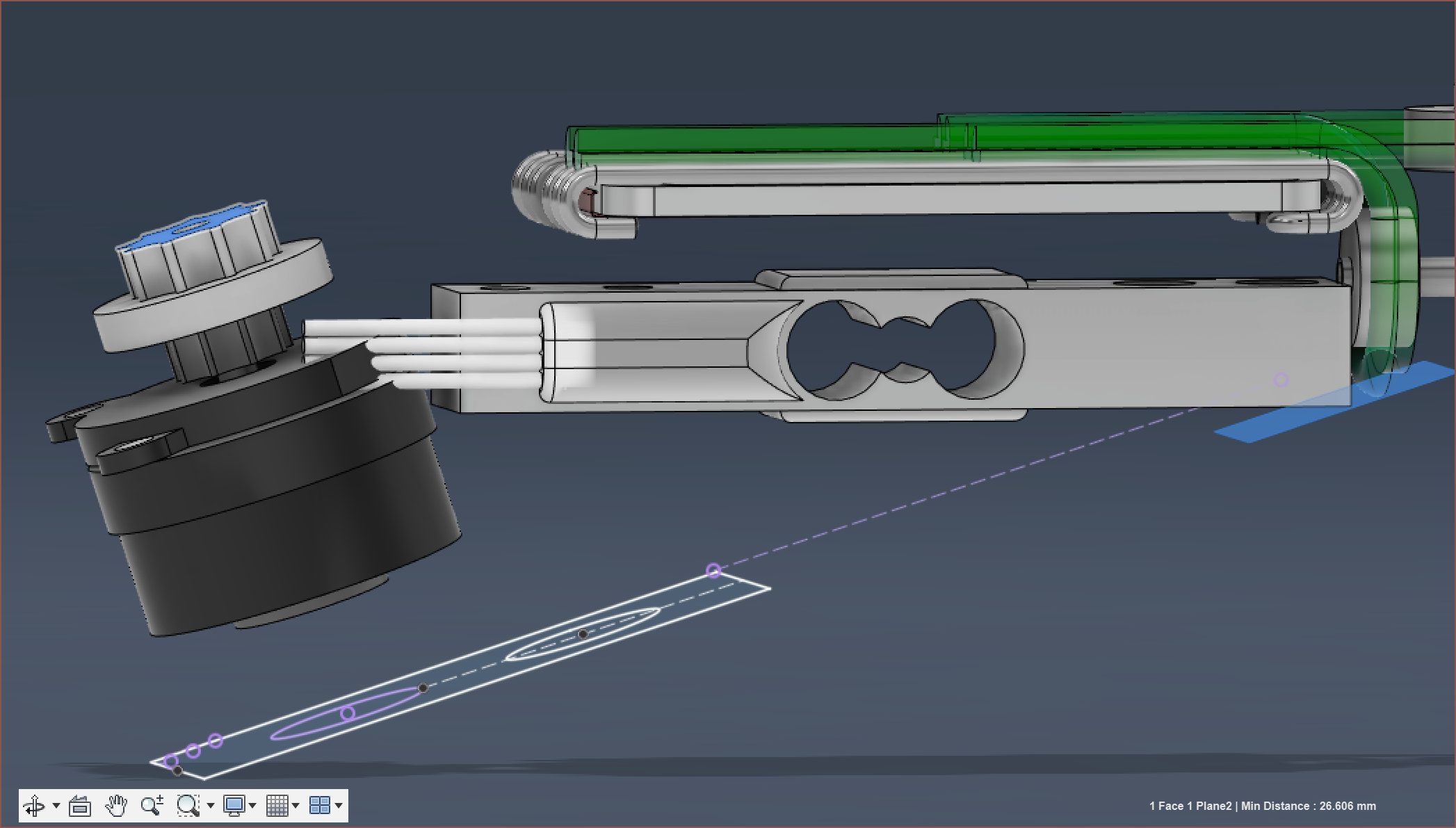
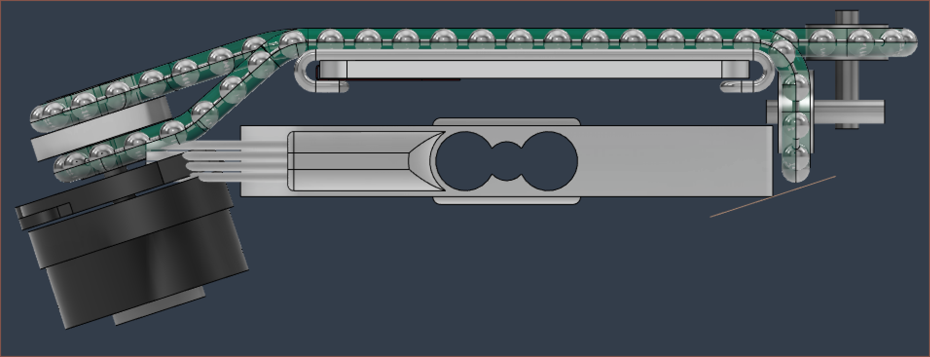
[M] Chain aligned
04/15/2023 at 17:36 • 0 commentsIt's been another 6 or so hours of modelling... once again.
So I started off with modifying the 3D pathway so that Fusion would generate a centre-pathway:
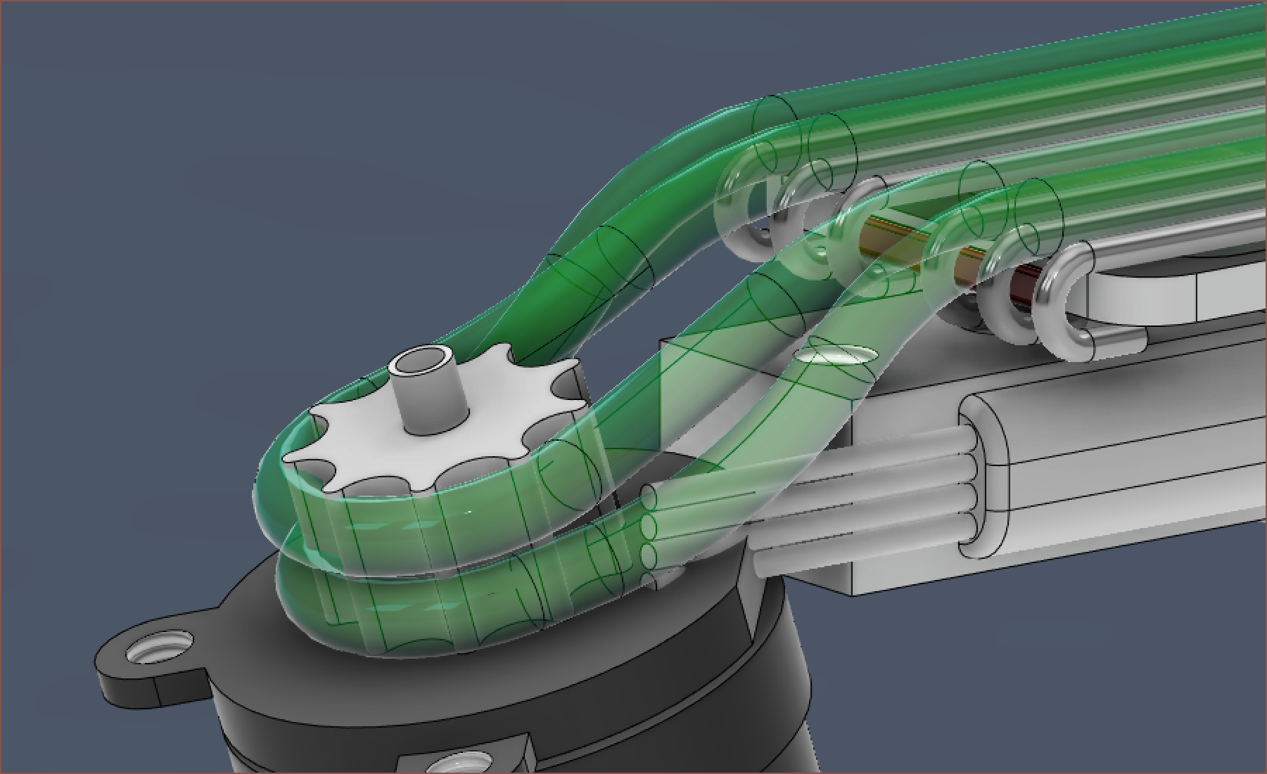
followed by a long process of a misaligned chain:
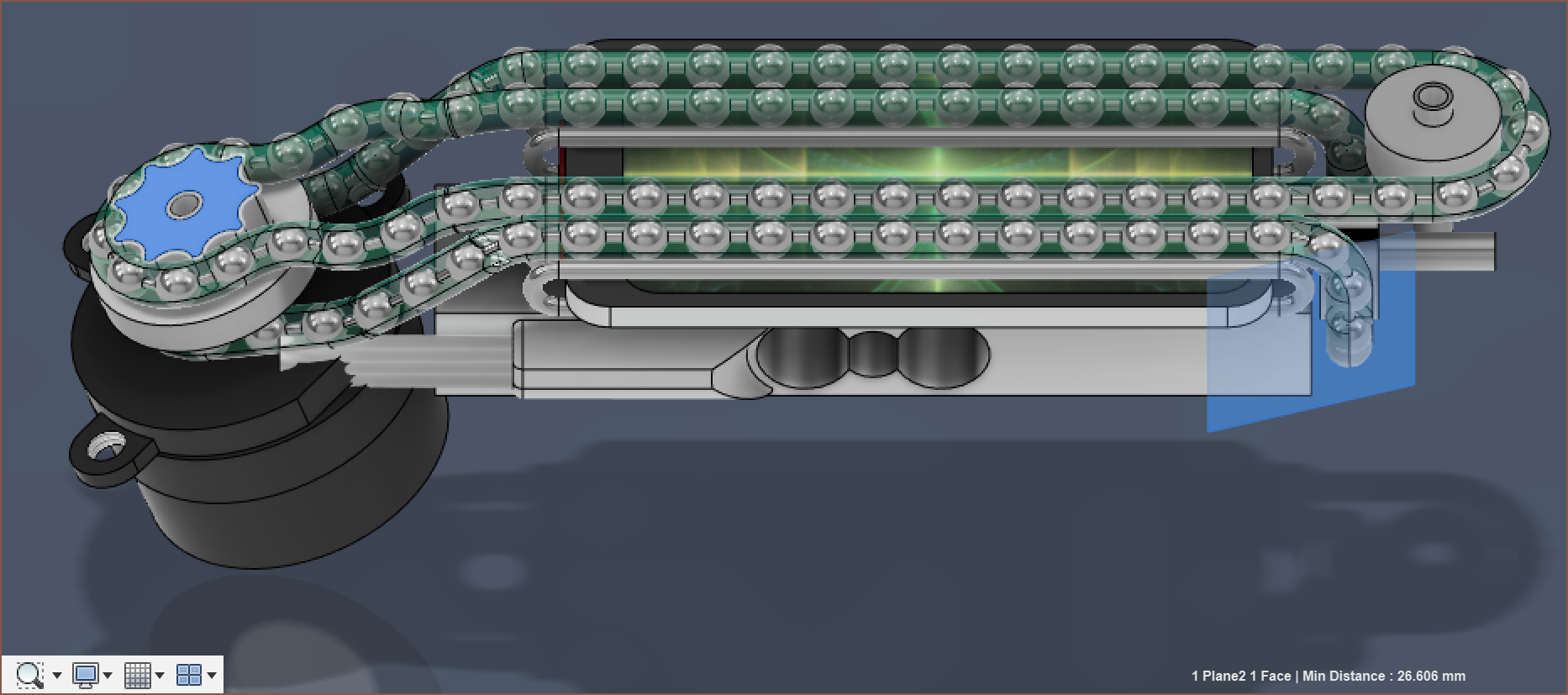
Eventually, I knew I wasn't going to get anywhere tweaking things until the distance from the pulley to the slide-tubes were the same for both the top and bottom paths.
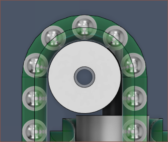
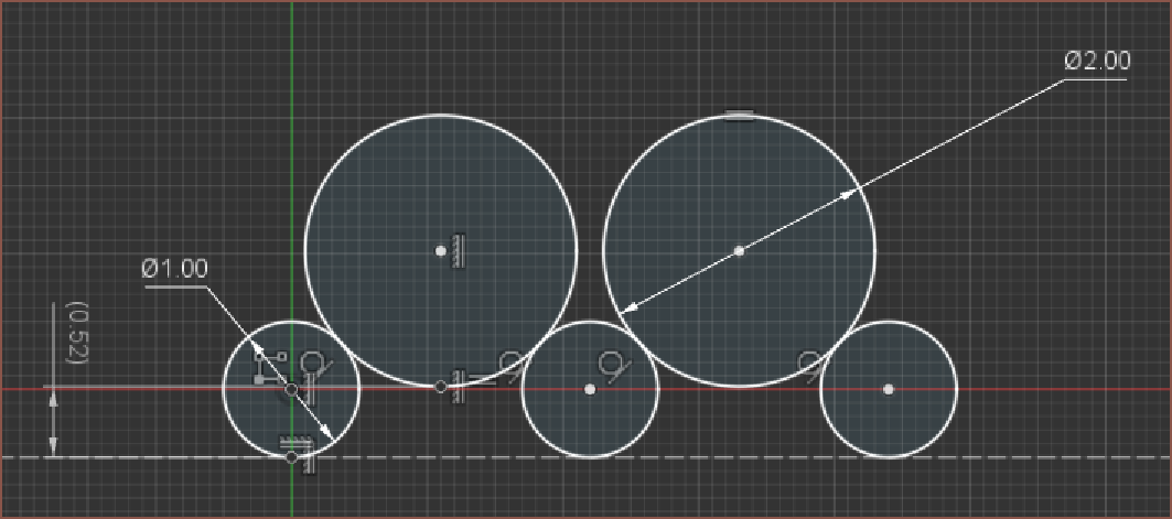
I decided to use a unique property of ball chains, which is that they can "compress" with absolutely no opposing force until the balls themselves are touching each other. Thus, I tweaked the pulley to have 2 different diameters, trying to keep over 2.5mm ber-ball distance for the smaller one and under 3.1mm for the larger one:
Then I had to tweak the paths so that I could get distances from the point where the ball left the pulley (as this is where the chain would be tensioned, with a 3.2mm ball-to-ball distance distance). Essentially, I shortened the bottom path to as low as it can go, and then increase the length of the top path to match:
Then I manually got the position for this bearing so that the ball positions were equal on both sides:
When it came to doing the same on the other bearing, there was an issue that I was going well below the minimum height plane:
Annnnnd... well I looked at this for maybe 6 minutes and deduced that there wasn't going to be any solutions to minimise this, so I decided to just bring down the load cell and increase the amount of space I can use for a 3D print to hold the screen. At least now I don't have to worry about how I'm going to hold the screen + sliding tubes now. At least the "flat height" is less than 27mm still, though this is without the top screw that holds the shaft onto the motor.
You can also see why I was weary of Tetrinsic Gen 1 having a width of 19.6mm. It's all too likely that stuff needs to be moved around and expanded, potentially increasing that size to 20mm and beond. 19.4mm is already just barely enough, going from the 0.8mm spacing in #Tetent [gd0090].
Anyway, this changes all the paths again and my original pathway now intersected with itself. Obviously, when you've got some differential pairs, the strat is to do things the PCBway.com:
This path starts 1 ball later than the bottom one, so the length is 3.2mm shorter to compensate. I also formulated the actual equation needed for the 2 bearings so that I didn't have to manually calculate it again.
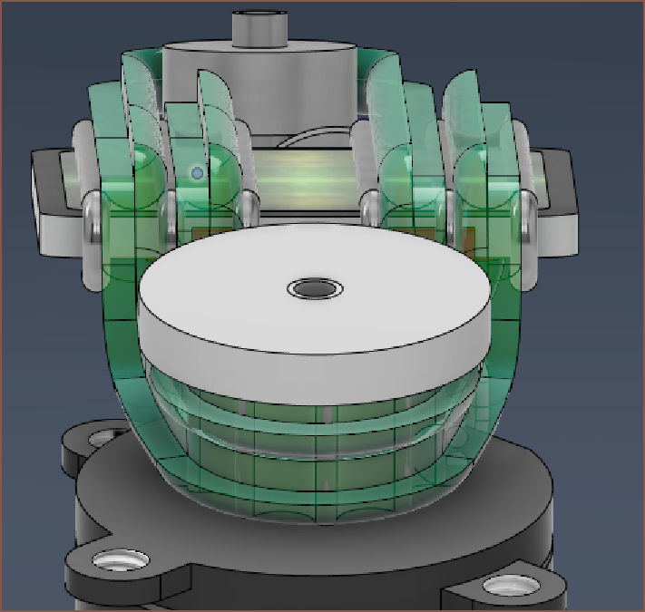
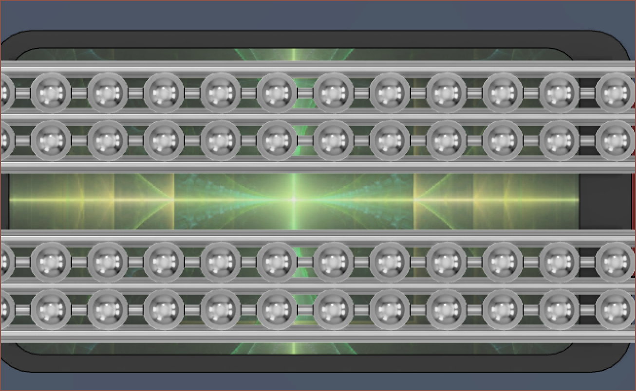
Now I've got some lovely, aligned balls. It also looks good from the side.
Now with all that under-screen space, I'm wondering if a solution exists to have the PCB exist there and send wires off to the angle sensor (just like the load cell wires).
- That sensor is the only one that is in a non-QFN package, so it seems like a simple and straightforward thing to do.
- Allows uninterrupted access to the 2 mounting screws.
- I don't have to solder an extension flat calble to the screen, which I guess negates the top point.
It's quite the tight fit though. There's only 3.35mm of space.
-
[M] Chain Pathway
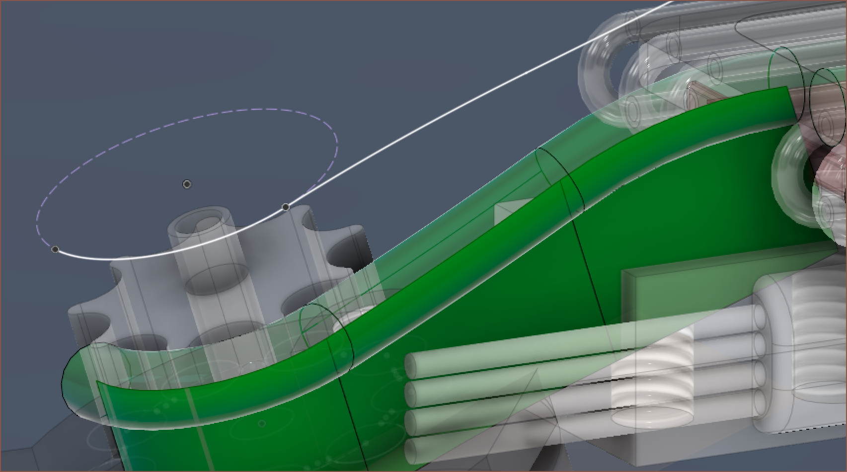
04/13/2023 at 22:25 • 0 commentsAfter all this time, I've finally managed to model the full 3D pathways of the chain. I've added a cap onto the printed pulley (not imaged) with the expectation that I'd insert a grub screw. To model the paths, I used the intersection of 2 extruded surfaces to obtain a sweep path:
I'm using the 2x10mm steel tubes for the pulley and the 2 bearings by going with MR72ZZ bearings that have an inner diameter of 2mm instead of 3mm. I can also get 30pcs 2x10mm tubes for the same price as 20pcs 2x8mm tubes from a different seller, and I need 24 tubes for 1 Tetent.
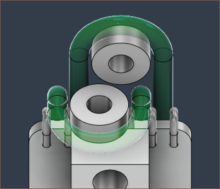
I've also decided to go with a continuous 1mm sliding tube design, putting one of the bends where the LCD wire is so that sharp cutoffs don't risk damaging it:
I've edited the spacings so that all bends are the same inner diameter of 1.7mm. The ball-chain now hovers 1/3 of a millimetre above the LCD. I just hope that 1mm is stiff enough for this job, and I may have to look into simulation in the near future to confirm this.
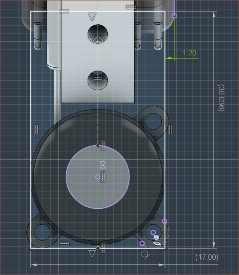
I've created a sketch that will be the basis of the PCB, and it turns out that it's essentially the predicted 17 x 30mm size:
I do worry about the amount of time sunk into this project (+ Tetent) though. I feel like a shareholder when I tell myself "This isn't WeWork! We need to turn a (time)-profit eventually!".
-
[M] Slow foundations
04/13/2023 at 13:30 • 0 commentsThis took somewhere between 7 - 9 hours to get to; it's a good thing I spent the time setting up #TrueTent [gd0143] . You have to realise that all designs since Tetrinsic 2.0 were more like detailed 3D sketches, and that there wasn't as much concern for file cleanliness or the pathway of the chain.
To start off, since #Tetent TimerSpy [gd0136] is being shelved until further notice, and that #Tetent [gd0090] has better ergonomics the longer it is, I decided to ease manufacture by not cutting the load cell at all:
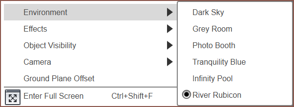
I found out that there's an all new environment option in Fusion 360 called River Rubicon, which is a rather nice dual shade of blue:
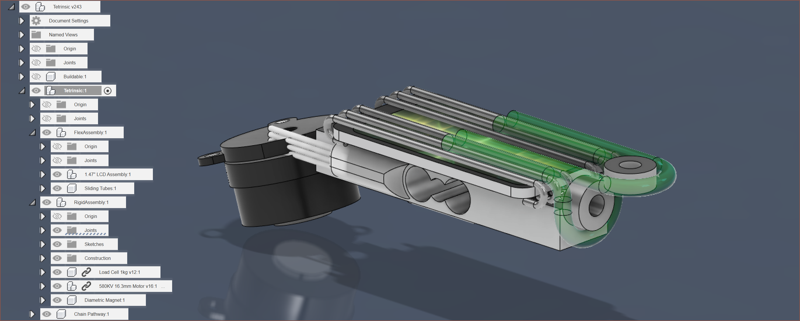
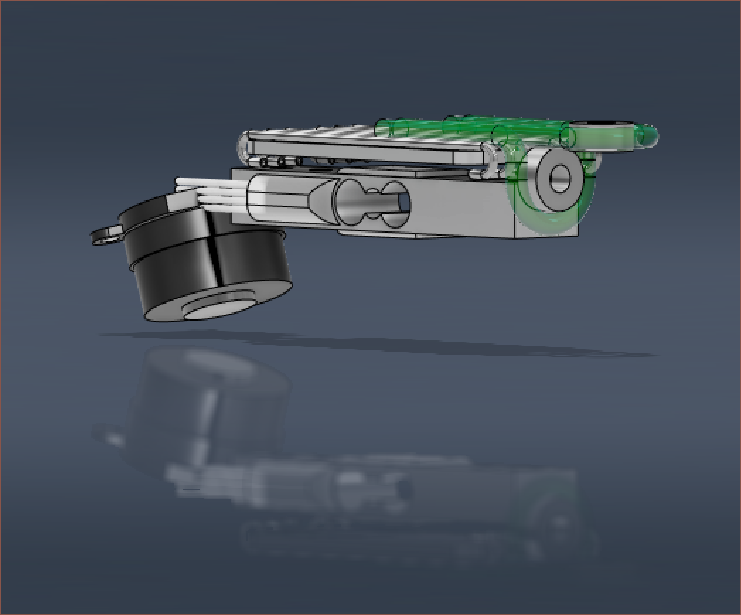
Showing the current design with the dual colour environment. Then I had to have a long and thoughtful computation on how I was actually going to route the ball-chain, and I decided to try and actually do the chain swap on the bearing side so that the motor side didn't have an excessively complex looking junction.
Very conviniently enough, the diameter of that curve is a fraction of a millimetre larger than 7mm, allowing me to use 683ZZ bearings. I probably should've checked, because these are actually some of the smallest bearings commercially available (that aren't something like £1 each).
I should also mention that I've decided to use 2.4mm chain since I've got that with me already, meaning that there should be no suprises with the feel or durability of the final assembly.
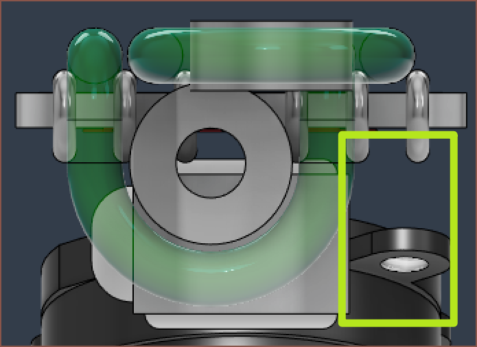
I've routed the chain like this so that the right side (of the image below) is as free as possible, should I need the space for something:
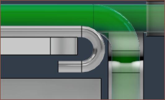
From this angle, you may also see why I've had to bend the 1mm steel tubes: there's not really any place to grab them if they were straight. I don't have any bending knowledge, so I'm going to assume to keep the radius equal to or greater than the diameter of the tube:
I'm also not much of a fan of this tube price, seeing as there are sellers that sell (specifically) 3mm tubes for a fraction of the price.
From my calculations, each one of the 6 tubes in the design is 45.7mm, requiring just under 275mm of length per Tetrinsic.
Back to the bearings, I've got to figure out a way of mounting them. I might use a small ring to shrink the ID from 3mm to 2mm.
The entire design looks to be on track for an 80 x 27mm footprint. This is an increase from the 66 x 24mm footprint in the concept design.
-
[R][T] Plans going forward
04/10/2023 at 22:45 • 0 commentsFinally... I've got a locked-in Tetent solution that also tries to borrow from TyMist (because a handheld input device is near useless without an output device that is just as portable) and I've started thinking of the detailed, full implementation of the solution. I also heard an interesting quote from someone commenting on a Facebook post about some engineering fail:
There's never enough time to do it right but
there's always enough time to do it twice. ― Facebook Guy
I find this hilarious, partially because I'm in a rush yet I've actively been trying to avoid this thought process before seeing it written for the first time.
This project... is going to take a while, mainly because the stuff I need doesn't exist yet. Something along the lines of:
If you wish to make an apple pie from scratch,
you must first invent the universe. ― Carl Sagan
The workload I've envisioned I need to do makes me wish I had a Tetent to create the Tetent.
For the Tetrinsic specific stuff, some of the things I'm thinking of using / implementing are:
- TinyUSB and FreeRTOS on the software side
- Not using Creative Commons for the hardware licence since they actually don't recommend it for such a purpose (which is news to me)
- Using a jig to cut 1*0.7*250mm stainless steel tube to 40mm lengths. It might even be part of the same jig that will be needed to splice the stainless steel ball chain.
- My mental simulations that relied on chain tension and a tempered glass screen protector sliding surface kept coming back with warnings, namely that the chains will still want to bend away from their proper position since infinite tension cannot be acheived.
- @RunnerPack mentioned that he wasn't enthusiastic with sliding chains across the screens and I couldn't shake that thought.
- I still fondly remember when I was sliding the chain through a metal trench/channel, having a similar appreciation as that one tungsten cube review:
[I] bought this cube to become fully accustomed to the intensity of its density, to make its weight bearable and in fact normal to me, so that all the world around me may fade into [...] gravitational inconsequence. ― Amazon Reviewer- It felt great that my fingers were able to frictionlessly move in their dominant axis but was solidly prevented from movement in their secondary axis. I can imagine this being extremely useful for walking and typing.
- Thankfully, the actual height increase is only 0.5mm and LCD light should still be able to pass though mostly non-eclipsed. The weight also shouldn't increase that much, especially since the tube is hollow. The hollowness should also allow for easy cutting, and I can't imagine the tubes deflecting too much from 500g of force.
- I should mention though, that I've just measured the chain I actually have and the balls are 2.4mm in diameter. Hopefully, 2mm balls feel almost indistinguishable, but this further increases my suspicion that 2.4mm is a more common size.
- Support for the TC358870XBG, which is a HDMI to MIPI chip that requires a microcontroller that communicates by I2C. Why not save some money, PCB space and programming time by letting a Tetrinsic handle it?
- Trying Fusion360 Electronics for the design of the PCB.
- Like TinkerCAD, EasyEDA is easy... if you don't need to make many adjustments/revisions (ie you know exactly what you're modelling and can create the thing first time round).
- I'm tired of spending 60++ seconds every time I want to slightly reroute a trace, when such a task should've been a 3 second click+drag.
- I'd probably have to create footprints for every chip I use now, but I'm learning about the program and there's a full wizard thing that creates the PCB and the 3D model too.
- The native 3D model generation is another reason, as well as the expectation that I'd need 5 custom PCB's to fully create Tetent.
- I might see if I can program the firmware in Rust.
- Why? Is C not good enough?
- It is... it's just that I'd like something that syntaxically looked like F#, and Rust does... marginally, if you squint.
- I'm really just in it for the "let" keywords.
- Fornjot is written in Rust and so it might be a decent idea to try and learn the language for #enSweepen [gd0096].
- Basically, I'm going to be staring at this code and maintaining it for tens of hours, so I'd like to at least spend an hour or two weighing in my options.
- [ok I've stopped writing to actually do some research into this]
- Ok it turns out that there's an entire thing called the ESP-IDF which is based on FreeRTOS, according to MicroPython documentation. That sounds like 3rd-party language support can live alongside C libraries perhaps?
- My main concern is TinyUSB, and there seems to be bindings for it.
- There's also the UF2 Bootloader, which is based on TinyUSB, allowing a user to drag/drop files to update the firmware. That does highlight another point, which is how to update all Tetrinsics when only one of them is connected via USB?
- Hopefully there's some simple way to do that over I2C. There's also a way to update over BLE.
- Oh, it turns out that espressif has a fork for TinyUSB.
- Hmmm there's display performance issues, and the syntax of the posters code looks a lot more like c++ than F#, but with even more '::' ! Ok... pass on Rust then.
- It also looks like C++ is absolute multitudes faster than MicroPython, and since each Tetrinsic has a lot of stuff to do simultaneously, it does seem like a simple yet inescapable choice.
- Or is it? Are there any frameworks that let me code in something else and it ports it to C?
- Yes. There's a fat list.
- Did a quick skim scroll and I thought I'd at least look at the ones that converted into multiple languages (so that I could say hypotheticals like "What if there's a python script in this otherwise C++ section of firmware? Dijobu, Igotchu.") and saw Haxe (cool and edgy name btw) and Wax.
- Not that much of a fan of Haxe syntax, but I'm liking the look of wax already:
- Yeah... might have something to do with the dark blue background and "let" keywords. You can also use (, [ or { brackets anywhere and mix/match too, wich is very nice.
- It does seem like wax acts like a nicer looking C, reading its limitations. Hopefully, I don't need C++ stuff. Both ESP-IDF and TinyUSB are written in C, so it doesn't seem like that much of an issue.
- Obvioulsly, the real question is if any of this would actually work for embedded systems or if they're intended for desktop programs only.
- Additionally, it does seem that the features present in C++ would be less tedious to maintain than a C or C-like language, though it's recommended by some redditors to use C if started out and C++ for maintainability.
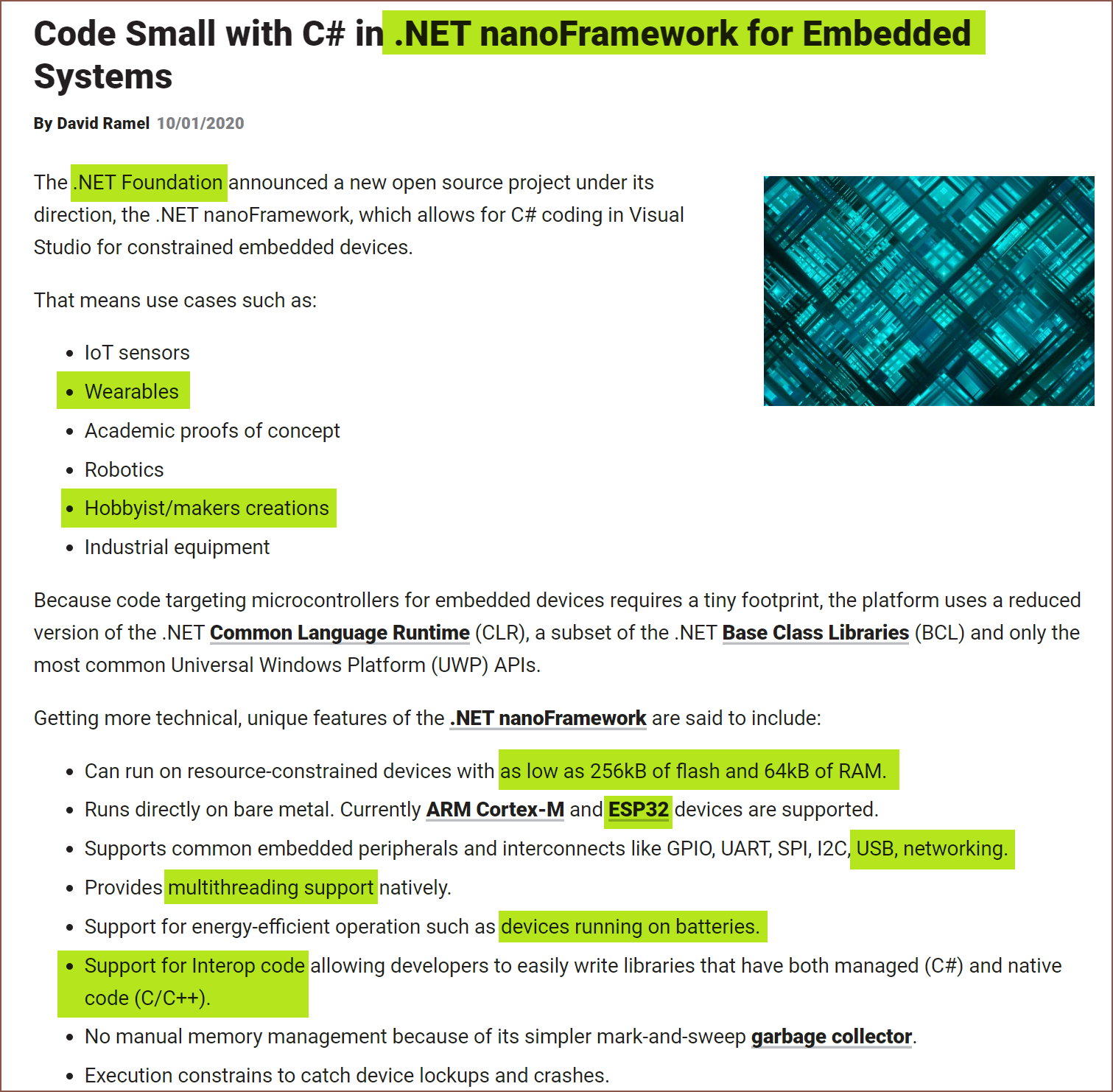
- Sigh... if only .NET could run on microcontrollers.
- Me: [dances like that one kid in a club]
- Reality: [slap]
- Turns out ESP32-S3 support... does not yet exist. I'd give it a go (because I suspect F# isn't a first-class citizen either), but I'm not all that fond of being landlocked and typing on QWERTY (or, at the very least, my current keyboard) to get that job done. This makes me think of:
You can’t solve today’s problems with yesterday’s
solutions. ― Albert Einstein
- By thinking of coding Tetent in C++ --> contribute to nanoFramework --> recode the thing in F#, I then come back to the first and second quotes!
- I'm mainly thinking of maintainability, in that I might code the firmware in 10 weeks, but I could need to maintain the codebase for 10 years. And remember, I've got more software projects to do after this, not including the hardware projects that need custom software to function. I say this, but I still haven't written a single line in F# yet. At the same time, F# and nanoFramework will likely stay in the sidelines if a relatively large percentage of the userbase only use it for side projects.
- Moving on, I'm thinking of using a small bearing or 3 instead of friction on the loop-around U shape I've got currently:
- This part mainly depends on achievable FDM print quality, but is also a longevity concern.
I'm trying to avoid time bankrupcy here, but this overall Tetent project sounds mighty time draining right now.
"Do it from scratch. Spare no expense! And never cut corners."
And we are almost bankrupt. ― Cave Johnson, quoting his father
It all sounds within my capabilities, but loooooooooong.
I wondering if I'll ever get all the way to the end,
but it's a risk I gotta take. ― STRAY KIDS, TOP (english version)
At the same time though, I'm wondering if I should just pack up this hobbyist innovation biz and reclaim my time, seeing as most my other projects all the same or larger in time-cost without Tetent, and that the 4x speed boost and quality-of-life improvement via Tetent will make it all too easy for Me In The Future to take on 8x the current workload, similar to adding more lanes to a highway only incentivises more people to drive.
-
[M][T] ESP32-S3 MINI and other changes
03/21/2023 at 22:43 • 2 commentsI wasn't sure if this log should be written or not but I'm going to do it anyway. Wait who said I had to write it? Let's speak it! Windows 10 dictation for the win with WIN + H!
History
So this all started yesterday when I was looking for a Bluetooth chip.
The reason why I was looking for Bluetooth chip was because I counted all the pins that I was using for the M032 and it was 20 / 30 pins available on the RP2040. It seemed that 6PWM gives me more control so I'm going to keep it in instead of getting another 2 - 3 additional pins. I looked at the LCD screens and I need 7 pins for both of them.
Then, because I plan to have IntProv on here, I looked into buzzers and what notes they could produce. It sounds like "passive" is the type I want, since "active" buzzers take in a solid wave and turn that into a solid note.
ESP32-S3 MINI
So, thinking of TimerSpy, I was thinking "Can we go all the way?" and looked for an SPI Bluetooth module. This is the cheapest one available:
![]()
And it had WiFi tacked on. At least it's BT v5.
This was all quite surprising. For some reason, this was an engineering sample even though there were 7000 in stock, there were 4 entire megabytes of flash and 408 kilobytes of RAM ! That's even more RAM than the RP2040.
So then I did a little bit more digging, and found the S3 MINI for £2.75:
And this is jaw-dropping for me. I didn't know that there were other chips beside the RP2040 with dual cores.
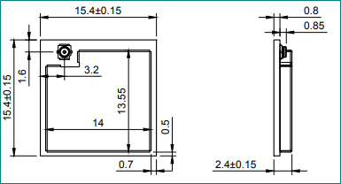
It's smaller than the WROOM module, but 15.4 is kinda gargantuan compared to the 7x7 RP2040 or 4x4 M032. The nice thing is that the oscillator and the antenna header is part of the module.
I counted the GPIO pins and found out that it's still 30. The good news is that I don't lose pins for Bluetooth. I believe the BOM increase is less than £10 compared to an RP2040 + 8MB FLASH chip + oscillator, and the PCB space would probably be similar even though they would be separate components. I can now have a wireless Tetent without having to install an extra board and interface with it. I guess I also get free Wi-Fi.
Looking at the pinout, there's a wall of GND pins so I'm thinking of having those connections on the top layer and root or the other pins on the bottom layer. This means that the module looks like this on the PCB:
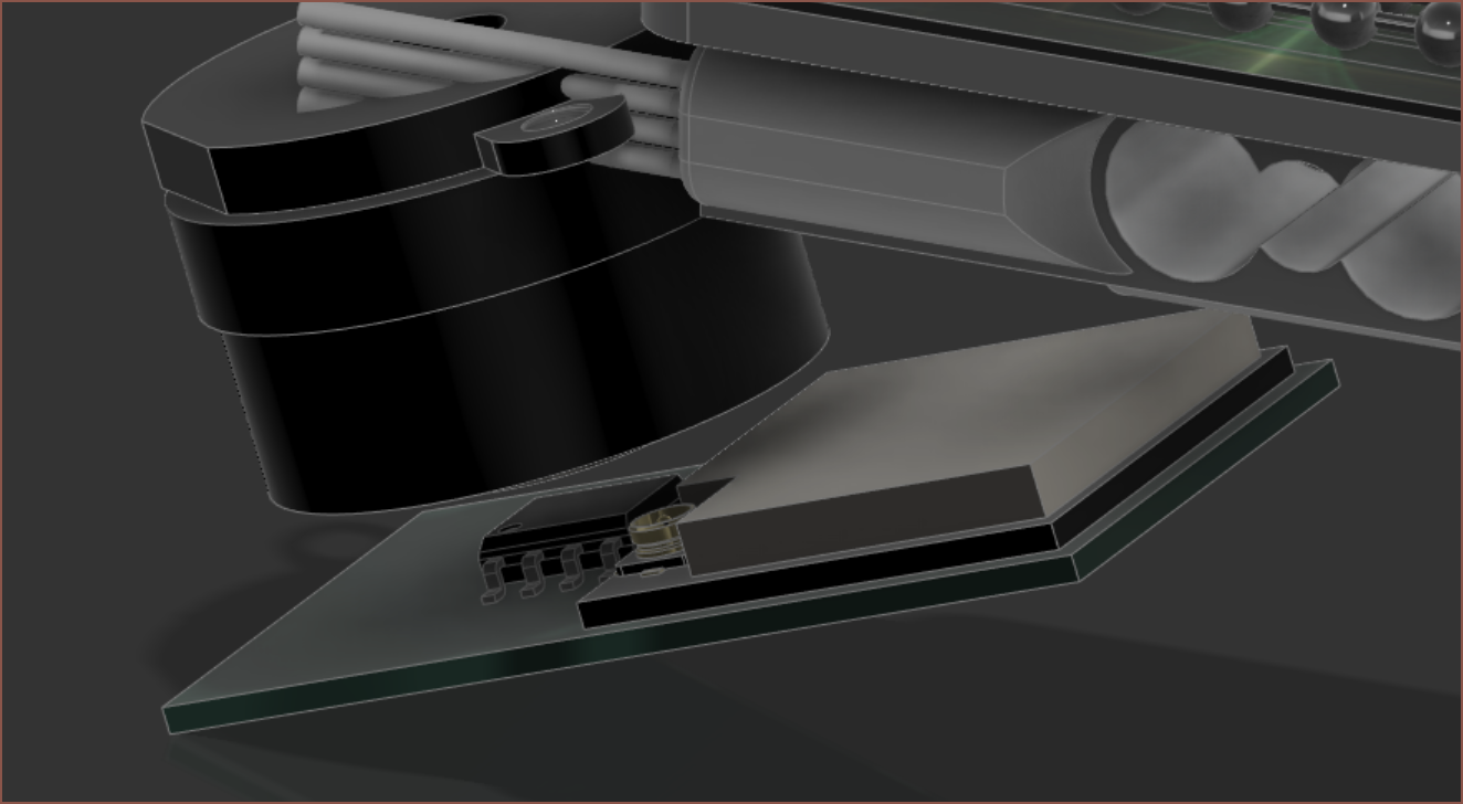
PCB space was one of the things I was trying to maximise. It allows me to obtain opportunities like this one.
Internal Measurement Unit
Turns out a 9 axis IMU singular chip is £16 on digikey. That's the cheapest one in stock anyway. AliExpress has (somewhat large) PCB boards for £4 and as low as £2 (shipped) if I went 6-axis.
I feel like I only need a 3-axis accelerometer to correct for the no-load force of the load cell when in a different orientation. I assume the polling frequency required will determine if I need to have this per Tetrinsic or if I can have 1 singular one in Tetent. I doubt a user would be changing accelerations often enough, but I am talking about 8-10g actuation ranges and walking (which is something I'd like to be able to do while typing) is shaky. The cheaper ones are just under £1 on AliExpress, though a fully manufactured board is still cheaper. The LIS2DH12 looks to be a good, cheap and small option that doesn't require many additional components and can run at least 1KHz.
Looking at the PS5 controller, it does seem that they go with 6-axis. I've gone down this list and searched it up on AliExpress, and the first one with a good price is the LSM6DSL. It's about £1.30 each + £3.21 shipping. I searched "IMU" on the store and there's a 10pcs listing for the BMI-160, which is £6.72 + £3.21. That BMI160 lists "augmented reality" and "immersive gaming" as potential applications which is what I'm looking for.
Conclusions
I think that, as long as I only need 1 per Tetent, using I^2C (or IIC, as some AliExpress sellers call it) should be fine for external boards. At least then I'm using 28 / 30 GPIO pins.
I forgot that #T^2 TyMist [gd0138] is no longer happening due to optical constraints, so audio output is once again required for Tetent... maybe. Well I know it'll sound better than using buzzers in Tetent and TimerSpy so I've been looking into USB audio interfaces with the EPS32 to see if it's possible.
I might try hybrid dictating and typing logs more often.
Tetrinsic [gd0041]
A motorised fader that is continuous, pressure sensitive, haptic and water resistant.
 kelvinA










 And this is jaw-dropping for me. I didn't know that there were other chips beside the RP2040 with dual cores.
  It's smaller than the WROOM module, but 15.4 is kinda gargantuan compared to the 7x7 RP2040 or 4x4 M032. The nice thing is that the oscillator and the antenna header is part of the module.
  PCB space was one of the things I was trying to maximise. It allows me to obtain opportunities like this one.