-
[R] Electrostatic and magnetic resin
08/15/2022 at 00:42 • 0 commentsTo start of my research, I looked into laser toner viscosity which didn't really find anything viscosity wise, because it turns out toner is a powder and a very fine one at that. There's even magnetic versions, suggesting that it may be better to have magnetic particles in the resin instead of magnets on the printer. As I guessed, the charged and magnetic solution could be combined for dark resins, which should result in even greater cleaning performance.
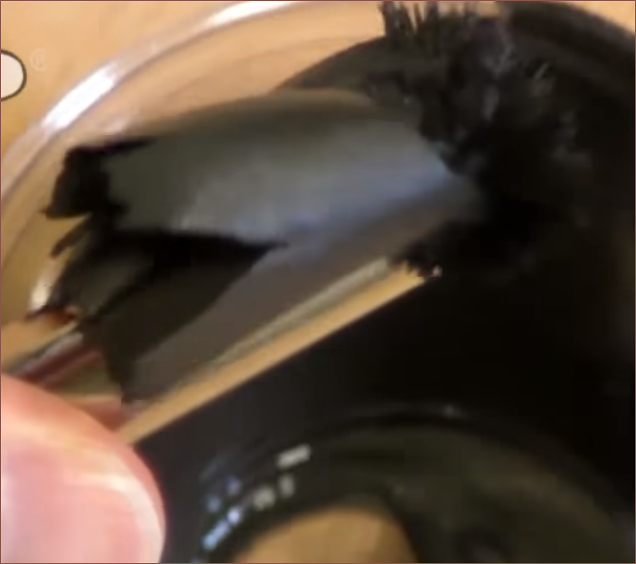
Then I looked into magnetic paints. I found out about erasable crayons and dustless chalk, but then I found this:
![]()
Ok... the paint just got rip-n-torn clean off the bottom of the transparent cup. This'll work, 100% no doubt about it.
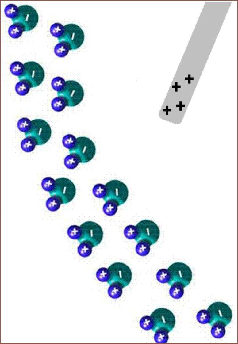
Now that the magnetic solution has been validated, I went back to researching about an electrostatic solution. I found a webpage that explained this school experiment I've long forgotten about involving a water stream and a charged rod:
![]()
The page says that polar molecules have a greater effect than regular dust. Speaking of water, it sounds like the relative humidity should be low, but that may only apply to generating static electricity by rubbing. Here's a video I found, and the force seems pretty strong even at a distance magnitudes further away than what I need:
I wouldn't imagine a vacuum being this performant at the same distance.
I also found another one that shows a cheap way to generate the charged plate needed for the printer:
This board can be powered from 3 cell batteries. From reading the comments, I was able to deduce that this one creates negative static charge. The commentor deduced this by seeing that the diode is pointing away from the output.
Conclusions
I can cut the LCD stepper motor (and slightly complex gear arrangement) solution I originally thought of and go with 2 light servo motors that only need 2 pins on the motherboard and no stepper driver controllers, since there isn't any high angle precision required (unlike the Arm Attachment). This reduces the motors needed for the Suspense + Arm Attachment to 19 and, more importantly, the SuspenseSmall to 11! Since 8 steppers are used for the Arm Attachment, they can all be mapped to the Monster8 and the main system can entirely be on the Manta M8P + EXP MOT. My eyes are now set on reducing the cartridge pumps from 2 to 1 per cartridge, and I'll write more in a future project log.
It seems that I'm going to push some of the required development to the chemical team of the project (which is just me some time in the future) and hope for a resin with embedded polar molecules. The attraction from the plate should work fine in small pockets (80um square, but ideally 40um), where mental simulations for trying the same pocket with a vacuum fails. All attracted resin goes back on the same PET film it came from, so the dream of "every single drop (minus probably 50-150ml for the minimum fill line) makes it to the print".
Also, I'm thinking that it might be possible to partially cover the side of the LCD with the charged plate, reducing UV exposure to the LCD and hopefully increasing its usable life. I need to do more research to see if this would work or if the still-exposed section of the screen would still deteriorate at the same rate. My current understanding is similar to silicon wafer yields, in that covering the screen reduces the area on the LCD that could be damaged, thus reducing the probabilty that there would be damage anywhere on the screen.
-
[T] New cleaning method required
08/14/2022 at 14:29 • 0 commentsCurrent simulations
My mental simulations suggest that the current roller solution would be unreliable, and it's likely the reason why my modelling speed has slowed this week; the roller assembly moves other assemblies around. I'm thinking that the resin may stick to the roller, but there is a probability that some resin is further pushed down along the edge of the part.
The simulation assumes that the top of the exposed area is fully cured, thus the only location for uncured resin is the boundary between solid and liquid parts. It should be possible to roll the X axis over the section to be printed to prevent the resin being compressed between the LCD and another material in the same layer, though this requires 2 applications on the PET. For a single application, it might be possible to move to press on the part, roll off to expose a different part of the layer and then roll back, pushing out the resin.
The simulation is using 0.2mm layers because I want to be able to draft print if possible and the higher the layer height, the harder it is to clean.
Possible solutions
The ideal solution is one that obtains a result similar to a cookie cutout of dough, whereby everything exposed sticks to the part and everything else sticks to the film. Additionally, the LED strip is ommitted, instead making use of the hight powered UV lamp that already exists overhead.
Since the LCD is light, thin, and for this printer, small, it shouldn't be too much of an ask to install it on a trapdoor.
For non-conductive materials, I'm thinking of electrically charged resin and something on the screen-side of the PET attracting the resin. Something like a toner printer maybe?
![The steps of xerography [12]. | Download Scientific Diagram]()
![廊 Face With Raised Eyebrow Emoji — Dictionary of Emoji, Copy & Paste]() Wait... things are getting real close to a laser printer now. The differences is that the laser step is ommited and the "fuse" (read: expose) step comes before the transfer (back to the film) step.
Wait... things are getting real close to a laser printer now. The differences is that the laser step is ommited and the "fuse" (read: expose) step comes before the transfer (back to the film) step.For conductive resins, I'm thinking of adding ferrous powder and having magnets on the screen-side of the film. I have a better feeling that this would work (magnetic putty is just an extremely viscous liquid, right), but the bigger question is making affordable and highly conductive resins. I still believe that liquid deposition into channels would be for the best. Silver paste may be expensive, but only a 1 layer (40um) thick trace would need to be deposited and would still exceed conductivity of 2oz copper traces, and the silver is only deposited where it's needed. I don't have to worry about reclaiming excess paste or the metal particles reflecting most of the UV light if it was in a UV curable resin.
Compute conclusions
Both solutions may allow the "every single drop makes it to the print" ideal that BCN3D and those 2021 researchers talked about. It should also be more gentle on small features, since there shouldn't be any contact (and if there is, very lightly).
As the X axis may now be responsible for cleaning and curing, the application rollers may be brought back for speed improvements, but right now I need a minimum viable product not a max velocity printer. Thus, this solution should remove:
- 4 stepper motors
- (so all the cleaning roller related motors and 1 motor is repurposed to move the LCD instead of the cleaning thread)
- 2 stepper drivers
- UV LED strips
- Most bearings and pullety from the design, as well as some 2GT belt
- The cleaning roller and the hand-cut aluminium channels
- Long strands of thread as a consumable, and the associated maintinance downtime
- This was one of the things holding up a compute. The problem was being able to get the thread into position and how the thread bowden would get to/leave from the roller assembly.
- 2 linear rails
Additionally, the Z height is likely to increase by 20mm.
Now I need to research how to negatively charge liquids and what voltages would be needed for the anode.
- 4 stepper motors
-
[R] Reusable supports
08/12/2022 at 17:45 • 0 commentsSo I went around researching other attempts of reusable supports and the comments of internet users.
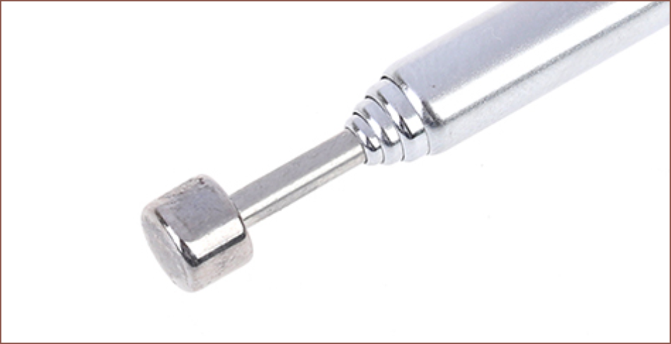
One of the comments in here talked about using telescopic antennas. Looking at build plates for SLA, especially top-down designs, it seems that resin prints can tolerate gaps, so I looked into a full-bed solution. Telescopic antennas would allow a finer height adjustment than stacking magnets (and magnetic cylinders of the same size and thickness in an alternating pattern so that the stacks don't push each other apart).
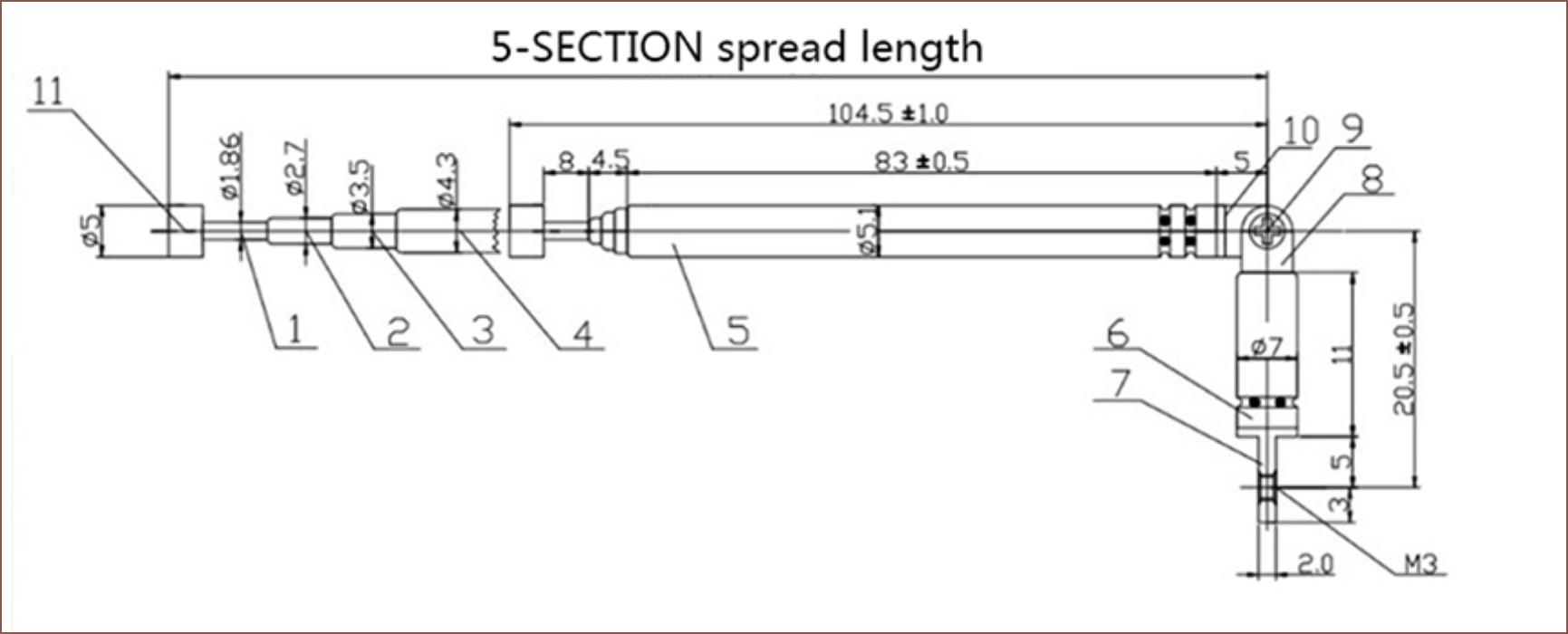
![]() I found some 27p/each antennas that extend up to 37cm, though in practice with many antennas, I expect the safe height to be 36cm. The end cap looks similar to the face of a magnet and flat enough to print on.
I found some 27p/each antennas that extend up to 37cm, though in practice with many antennas, I expect the safe height to be 36cm. The end cap looks similar to the face of a magnet and flat enough to print on.![]()
5mm sounds like an ok size.
165mm / 5 = 33
515mm / 5 = 103
33 * 103 = 3,399
3400 * 0.27 = £918
However, that's not an OK price. Apparently, the system in the hackaday article was or is estimated to be $10K, so that's a 10x reduction, but it would need another 10-20x reduction to be financially feasible. If I assume that I can go with a 10mm distance, the price drops to £239.
For this concept to work, I think it would have to be 3D printed in order to get that kind of precision but cut out labour and shipping costs. In terms of material usage, it's a fair assumption to assume that almost all the volume needed for this bed would use resin. Thus, for 10mm square size and print dimensions of 520x170x100, 8.84 litres of resin would be needed. For a reasonable price, that would require £4/L resin. In my opinion, that would be a nice price for the stuff anyway since I've lived the lifestyle of £5/kg PLA filament. The factory delivered 11kg of the 20kg I ordered for £55. 1kg of filament is 1.3kg of weight including the spool and box, so a shipping charge for a 14.3kg delivery was also built into that price.
If conductive traces could ever be printed cheaply, it could even mean that each telescopic pole can become a linear actuator like this.
-
[T] Magnets for reusable supports
08/11/2022 at 21:12 • 0 commentsI just realised that resin can adhere to room temperature metals, unlike FDM. This could simplify the resuable supports idea I had in #SecSavr Sublime [gd0036] where magnets would be stacked in a tower. The first magnet will be lightly press fit into a printed housing to keep it from moving.
This might be more sustainable in the long term than a supports printed from the more versatile recyclable resin I found talked about a few weeks ago. The researchers use ethylene glycol and heat to break down the printed part back into resin that can be used in the printer again, and can be done so up to 4 times. That already sounds miles better than the kind of hoops you need to go through to recycle FDM waste. The drawback is that the parts aren't fully cured from UV alone, which might make layer cleaning difficult, as well as bring in safety concerns. I wonder if higher viscosity resins could eliminate these problems, because this resin would work great for draft prints aswel. There's also this article talking about a more recent method and I'm reading it right now.
Anyway, magnets don't have those limitations and print time might be similar, but the height that can be used is dependent on the max height of the pick+place attachment. That PnP could also be doing things like inserting nuts or magnets into the part, so there's now a strong reason to obtain a higher height than what would be needed for PCBs.
-
[A] Proposed technology name: L^3
08/11/2022 at 20:04 • 0 commentsContinuation of https://hackaday.io/project/184896-secsavr-suspense-gd0105/log/205183-t-technology-naming
I think I'm just going to have something that gets to the point and is easy to imagine:
- Liquid Laminate Stereolithography (LLS or LLSL)
I could do the same strategy as BCN3D (acronym uses "lithography" instead of "stereolithography" and Stratasys (Programmable PhotoPolymerisation -> P³) to have
- L^3 for Liquid Laminate Lithography
Looks better in marketing (P³ looks more advanced than PPP for example), but again, to get the point across, I'm likely to just say "liquid laminate stereolitho". I actually don't understand where the "stereo" part of SL even comes from, since all definitions of SL only refer to the specific art of curing a vat of photopolymer with a laser. Looking at this wikipedia page makes it seem that I could just throw anything infront of "lithography" anyway, and that might be why BCN3D has chosen to ommit "stereo" from their technology name.
Ok. "L cubed" it is. Or is it "L 3"? I've been saying "P 3" for Programmable PhotoPolymerisation, but I say "Sol Squared" for #SecSavr Sol^2 [gd0045] and "T Squared" for #T^2 Tiles [gd0095] so I'm just being consistent.
-
[T] String bowden and 2060 Z
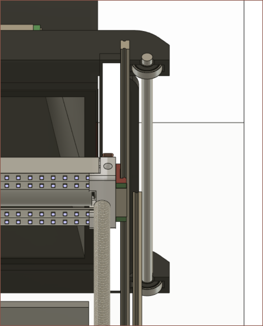
08/07/2022 at 20:46 • 0 commentsSo I've been slowly working on the case, and since the Roller Assembly moves a lot of things around, I've gone back and have mostly been thinking about the bowden tubes for the cleaning string (and the LED wires). My original plan was to use a tape measure as a cable chain, but it seems that it would only work if the U is in the horizontal plane. Thus I'm looking at my options that eliminates the possibility of the bowden tubes hitting the PET film.
![]()
I've also been looking into how to hold the Z axis beams up. I've decided on trying out a 2060 and having that connect to 2 2020 beams to make an I-beam like shape. The case will go behind the rail to improve aesthetics. The 2060 likely would also hold each half of the case together. I am getting a bit concerned about space since I don't really want to exceed 605mm, but so far it isn't looking like there's going to be that much space for the cartridges (I'm putting in 4 of them) and PET rolls which will likely be at the bottom corners of the printer.
-
[M][E1] Small Case Shape
08/06/2022 at 12:24 • 0 comments![]() This is the expected look of the SuspenseSmall. I want to get it to look more like something Brother would bring to market than some one-man-band DIY. The cleaner it looks, the easier it is to keep clean. I still need to think of a door solution. It might be a sliding acrylic/polycarbonate door, but a transparent rolling sheet (like rolling blinds) is also an option.
This is the expected look of the SuspenseSmall. I want to get it to look more like something Brother would bring to market than some one-man-band DIY. The cleaner it looks, the easier it is to keep clean. I still need to think of a door solution. It might be a sliding acrylic/polycarbonate door, but a transparent rolling sheet (like rolling blinds) is also an option.[E1 7th Aug @ 02:33]
![]() Pretty nice to see how similar to the 3rd concept design is to the current design. Oh, and I'm going to print in grey:
Pretty nice to see how similar to the 3rd concept design is to the current design. Oh, and I'm going to print in grey:![]() I don't actually know how much filament the testing stage of is going to use, and quite a bit of the filament budget is for light sensitive resins, so I thought it would make more sense printing in a dark material instead of white.
I don't actually know how much filament the testing stage of is going to use, and quite a bit of the filament budget is for light sensitive resins, so I thought it would make more sense printing in a dark material instead of white. -
[M] Slighty more Z, Roller cover and X rollers
08/04/2022 at 16:39 • 0 commentsJust done a few small tweaks. Due to the Z rails being slightly short, I left 10mm of Z height on the table. Extending the rails only increased the BOM by maybe £2 or something. The SuspenseSmall is now at a 240mm Z height.
![]()
Next, I've added the concept rollers for the X axis. These are cut from the same polished 19mm tube as the roller. So far, the Suspense would need a metal saw (for the aluminium channel) and a tube cutter, which I don't think is that bad. I'm also hoping that I can design the printed parts to fit inside the Ender3 (and various clones).
![]()
The transparent box is the 605*305*605mm bounding box of the SuspenseSmall. I've also added a cover to the top of the cleaning roller, which also has a channel for the string. There's not much clearance though, so I'm still wondering about how maintenance is going to work. I just hope that the string is consumed slowly enough to only have to worry about it. I'm thinking of holding the cover with magnets.
![]()
Reducing the required controllable motors of the Suspense to 22 has resulted in a notable saving on the BOM. This is under the assumption that a mini servo motor can be used to push the continuous fibre to the fibre arm roller and that the conductive silver paste can also double as solder paste. I can't imagine the second point going well, but I just remembered that I can print a support layer over the PCB that would act as a dissolvable soldermask stencil, though the PnP may not be usable. There's also connecting both Z axis motors to the same stepper driver, a method of using a servo/DC motor for the string puller instead of a stepper or just using a cheap stepper extension board and using 3 spare pins somewhere. Perhaps there's a slow curing silver paste that will allow the PnP to place the components in before it solidifies.
![]()
-
[T] Merge Application Rollers with Screen Block
08/03/2022 at 00:10 • 0 commentsA new solution has been detected...
The wide distance between the roller shafts on the Screen Block I just modelled made me realise that, with the right optical endstop and PET roller setup, I could eliminate the independent application rollers. I'm using optical endstops everywhere because they're quieter and give me the opportunity to move past the endstop if needed. My idea is to have a long strip that extends from [x axis limit] all the way to [absolute max x axis limit].
Benefits
- Removes 2 steppers, saving >£10
- Due to the removed steppers, it becomes possible to M8P + Monst8 + 2x MOT, saving around £13.
- Removes 4 100mm linear rails, saving £20.
- Allows more space for cartridges in both length and height.
- I may need to rethink my strategy for holding them, because I can't imagine having so many kilograms cantilevered at each cartridge is going to work out for me. The current idea is to make the 5 cartridges part of a shelving unit and it's the entire unit that a user has to remove from the printer.
- Removes 2 endstops. Probably saves pennies but those endstops are also some of the furthest away ones from the expected motherboard installation location.
- Makes assemby easier and reduces CAD modelling.
- The PET film will have a steeper angle, further improving peeling performance.
- Ideally, for prints where there is an adjacent screen area to move, the Screen Block will move to said area and the PET film will cleanly peel away from the part without much worry about suction forces at all.
Potential hurdles
- When the Screen Block moves away from the cartridge. there would be more slack in the PET than with the original plan. This probably won't be an issue in practice, as I can think of a few ways to resolve this.
- All material has to be applied onto the film or sucked back into the cartridge. I can imagine that this would be a similar difficulty to fine tuning the filament-end-forming script on an MMU before the filament is removed from an FDM hotend.
-
[M] Screen Block
08/02/2022 at 21:41 • 0 comments![]()
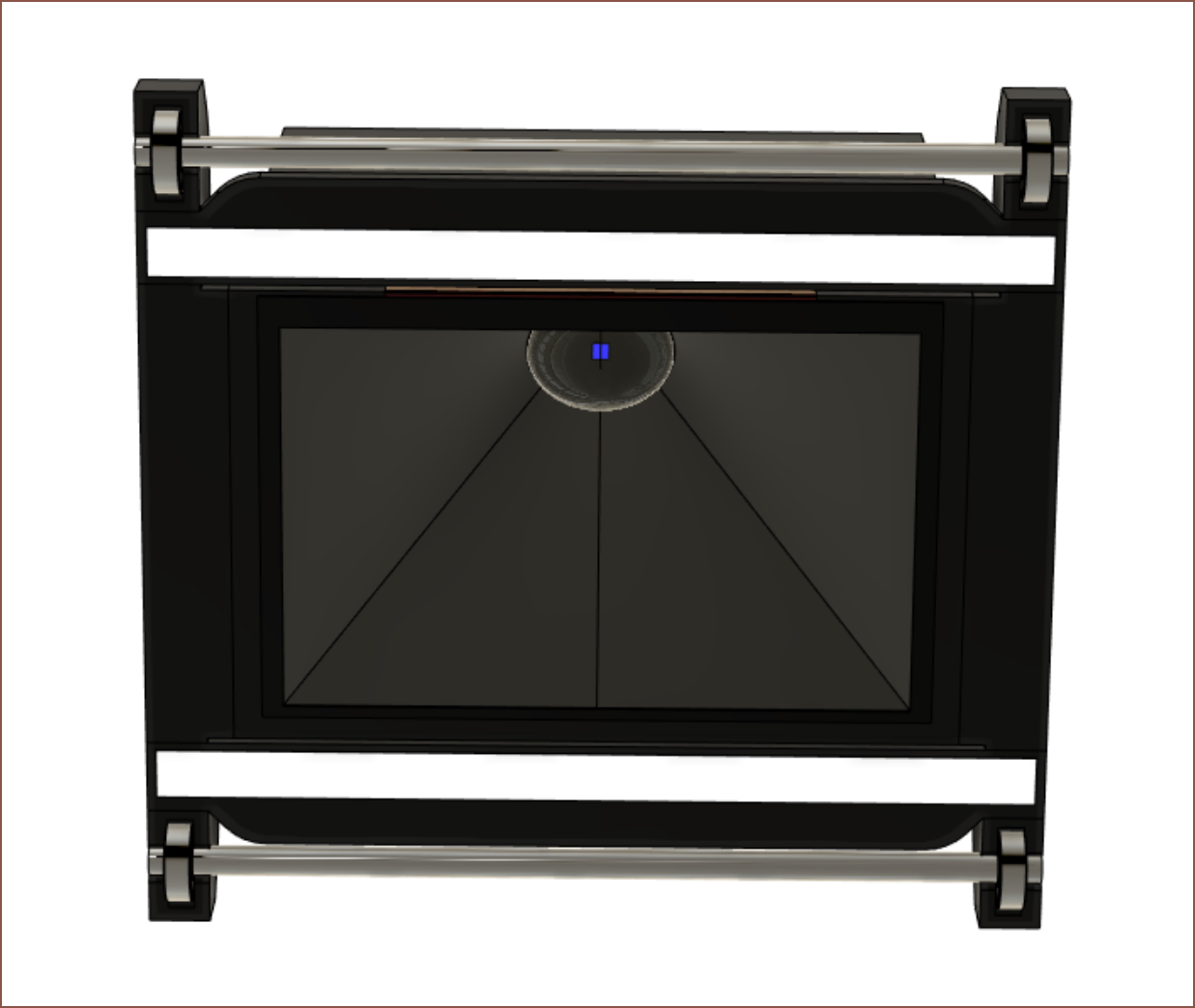
It seems that every 3D printer "head" I design is relatively large. This one is 224*236*206mm. This is the screen block. Usually I try to refine blocky looking designs, but it looks fine and the 6028 fans are close to the edges anyway. Up to this moment, I was actually planning on using a 16mm hose to duct air over to the block, and this entire time I've been wondering hwo I'm going to deal with the hose when the block is closest to the side the hose enters into. I've instead gone with a dual 6028 solution.![]() I'd probably have to change it for something more secure, but for now I'm thinking of pushing in the 608 bearings into some channels. The white LED bars are the dual scanner sensors. I've heard that they're too fragile to take out of the plastic housing that they come in, so I've just left them as-is in the design.
I'd probably have to change it for something more secure, but for now I'm thinking of pushing in the 608 bearings into some channels. The white LED bars are the dual scanner sensors. I've heard that they're too fragile to take out of the plastic housing that they come in, so I've just left them as-is in the design.I've also got to think about how the block with be attached to the X axis slider.
[A few mintues later]
![]()
Hmmm and I would've gotten away with it too if it wasn't for that meddling plastic tab on the CIS. It's not like it would've helped much if it was ommitted anyway. I wont be suprised if the SuspenseSmall ends up being 605*605*305mm (H*L*D). Maybe small enough to put on a table or one of those "heavy duty" shelves on ebay, but relatively large compared to the print area. At least it should still compete well against the Photon M3 Max, which has a 9mm shorter X and 70mm longer Z axis.
[23:47] I just realised that since I've got scanner sensors on the screen block, I can actually remove the need for scanners between the application roller and screen block. That's £17 saved and 60mm of X footprint that can go to something else.
Liquid Laminate Lithography 3D Printer [gd0105]
The best of resin with the best of filament; is such a 3D printer possible?
 kelvinA
![The steps of xerography [12]. | Download Scientific Diagram](https://www.researchgate.net/publication/269476121/figure/fig3/AS:669991582044186@1536749849632/The-steps-of-xerography-12.jpg)
 Wait... things are getting real close to a laser printer now. The differences is that the laser step is ommited and the "fuse" (read: expose) step comes before the transfer (back to the film) step.
 I found some 27p/each antennas that extend up to 37cm, though in practice with many antennas, I expect the safe height to be 36cm. The end cap looks similar to the face of a magnet and flat enough to print on.
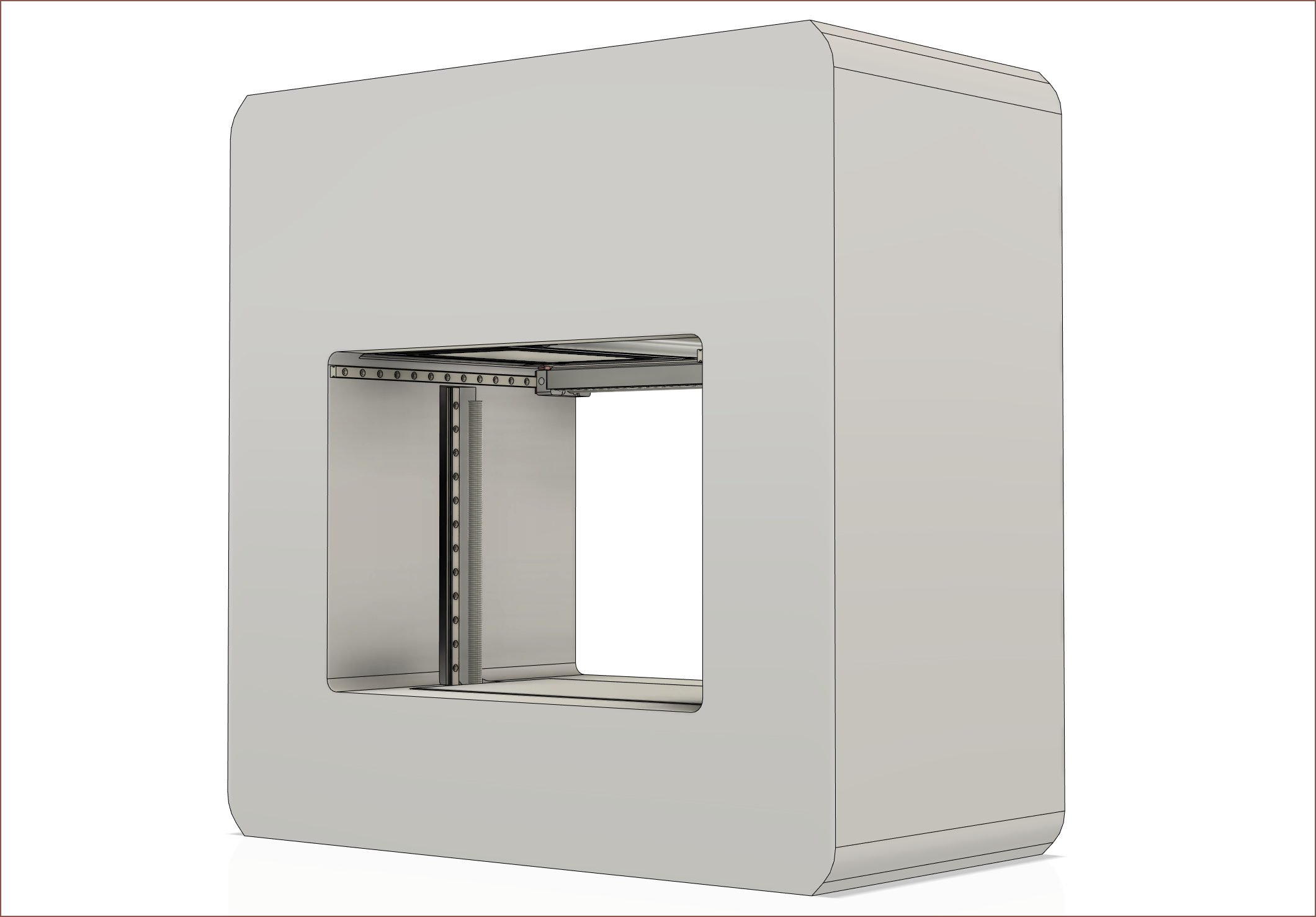 This is the expected look of the SuspenseSmall. I want to get it to look more like something Brother would bring to market than some one-man-band DIY. The cleaner it looks, the easier it is to keep clean. I still need to think of a door solution. It might be a sliding acrylic/polycarbonate door, but a transparent rolling sheet (like rolling blinds) is also an option.
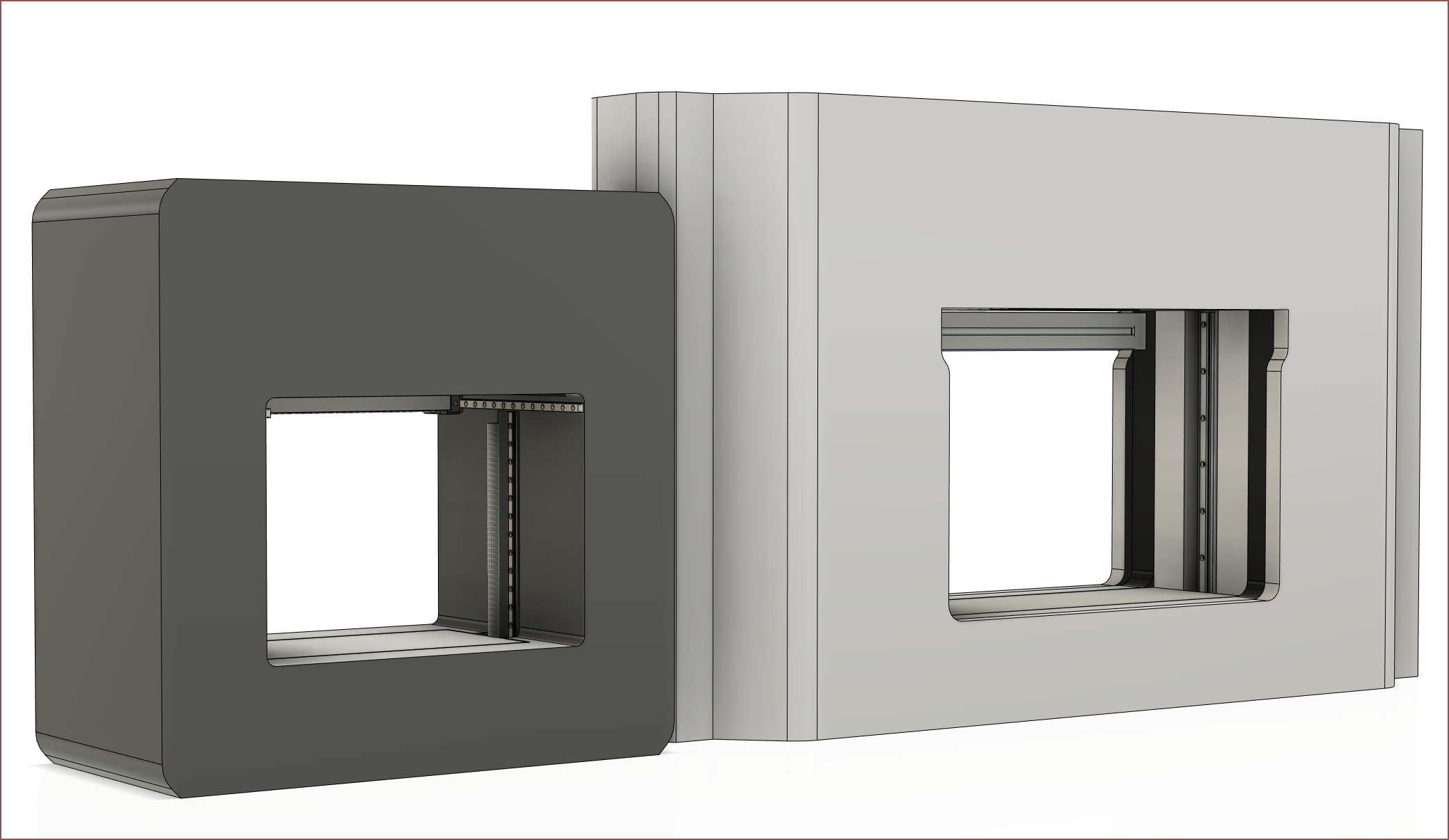 Pretty nice to see how similar to the 3rd concept design is to the current design. Oh, and I'm going to print in grey:
 I don't actually know how much filament the testing stage of is going to use, and quite a bit of the filament budget is for light sensitive resins, so I thought it would make more sense printing in a dark material instead of white.
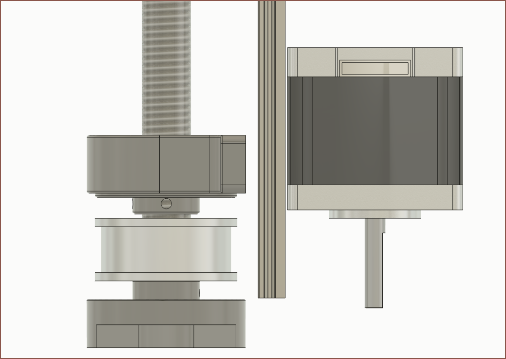
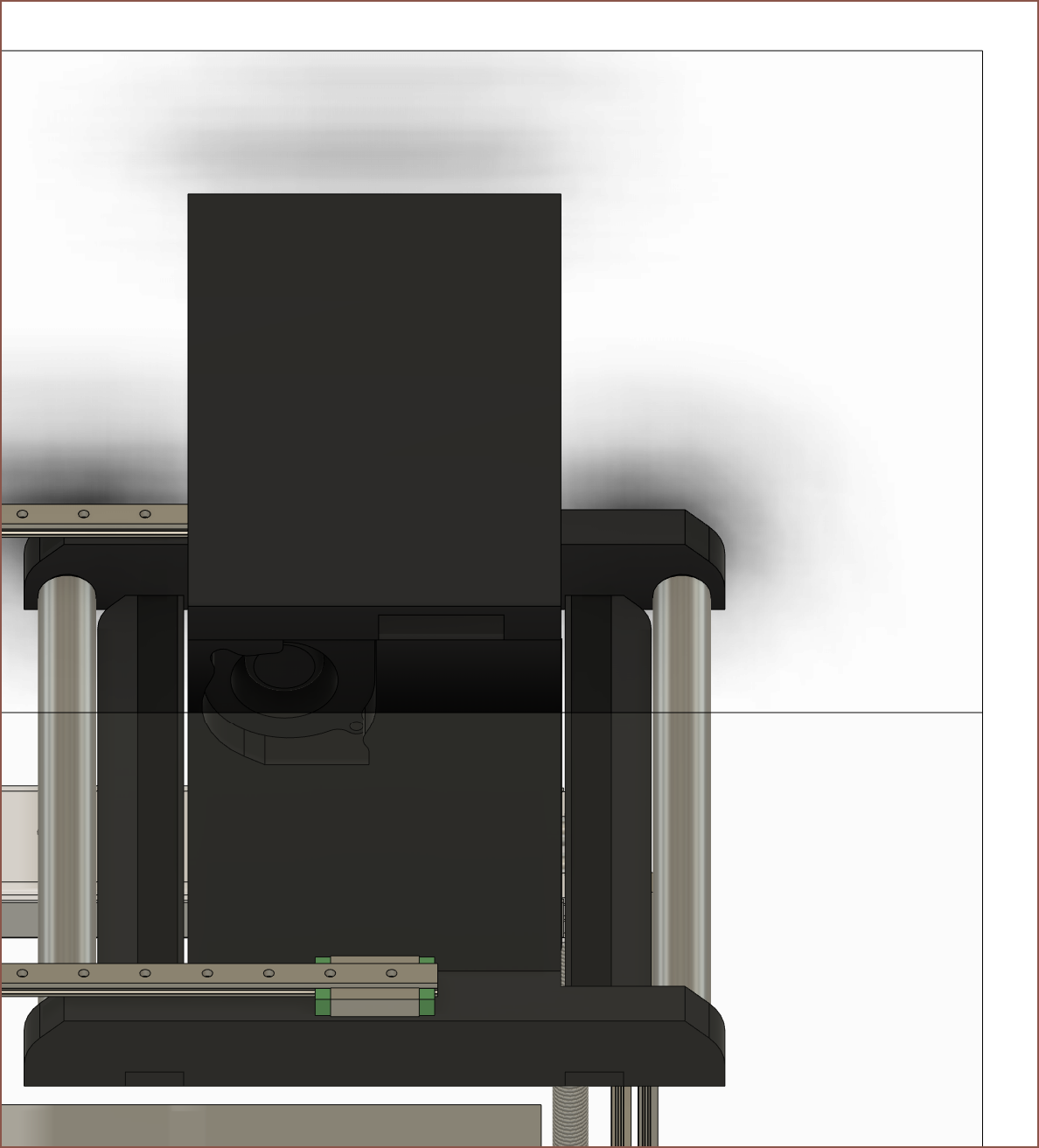
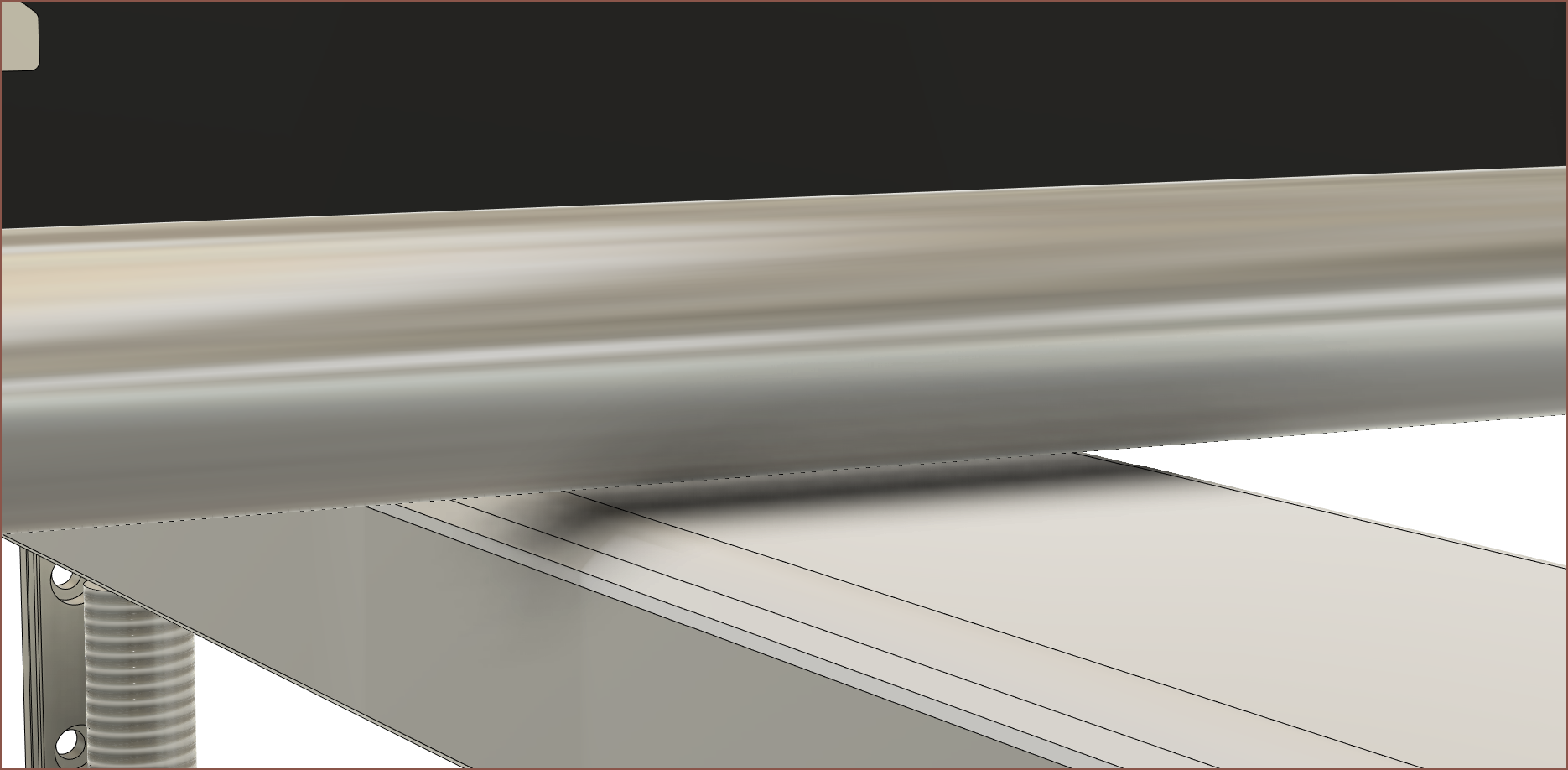

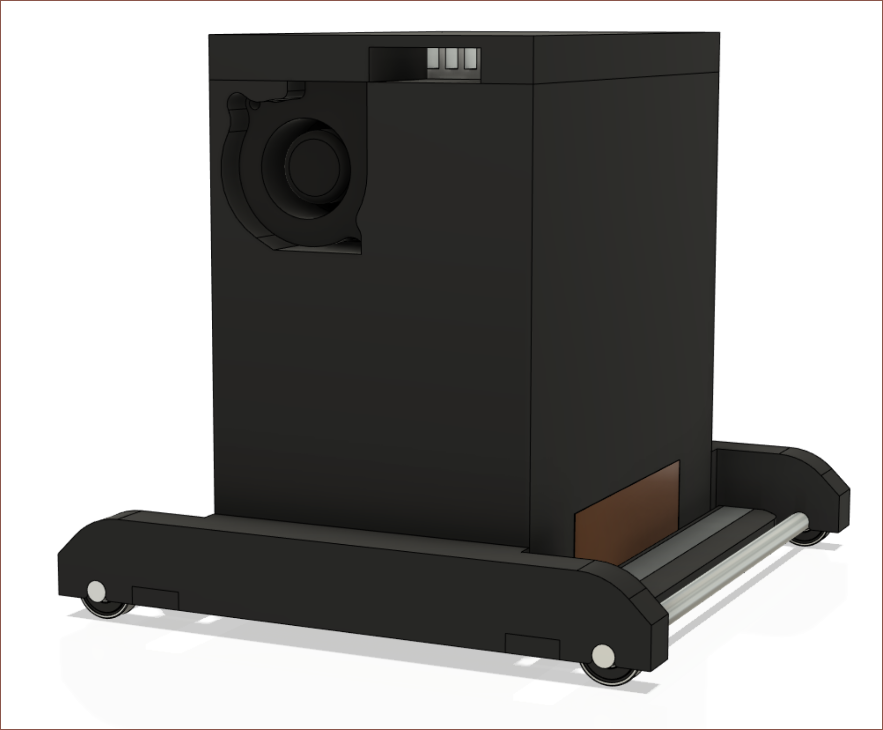
 I'd probably have to change it for something more secure, but for now I'm thinking of pushing in the 608 bearings into some channels. The white LED bars are the dual scanner sensors. I've heard that they're too fragile to take out of the plastic housing that they come in, so I've just left them as-is in the design.