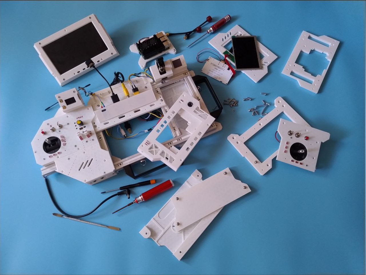
It's a bit disappointing when it took a lot of time to do things but these things sort of can't be shown clearly because they are not visually significant and quite messy.
More after the break.
---------- more ----------
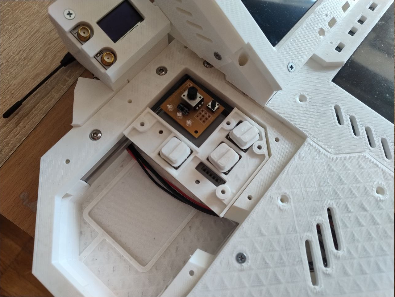
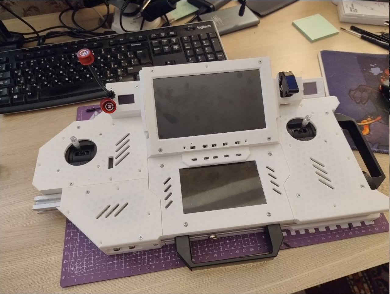
Those input boards were put together and inside their respective case places, like this primary screen part:
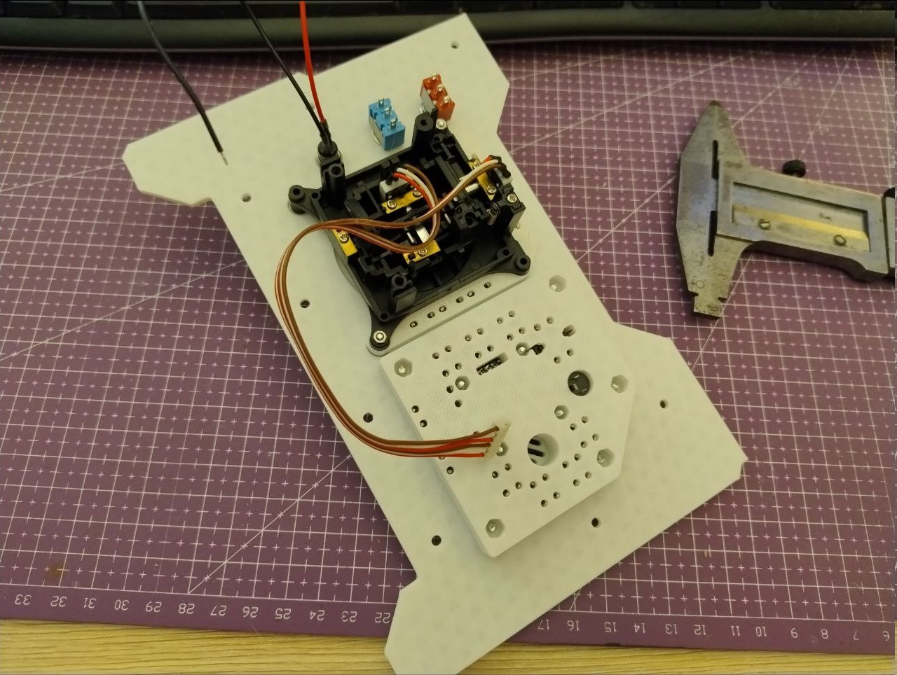
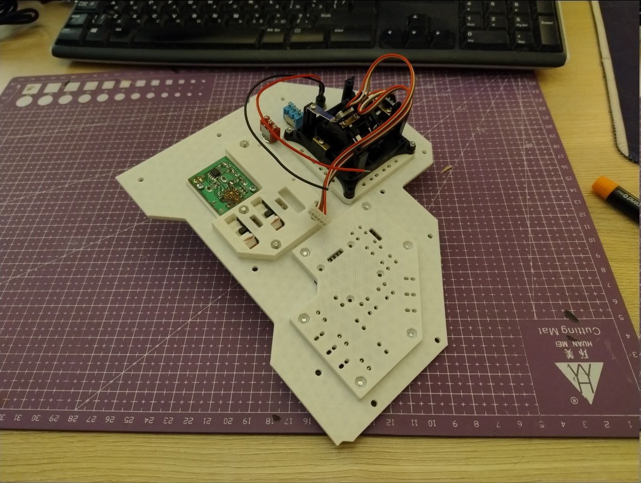
And that left part with some more modules, including all the wiring between input boards and input processor: No proper firmware for the input processor yet, but i did a little test that schematic is correct and soldering was done properly.
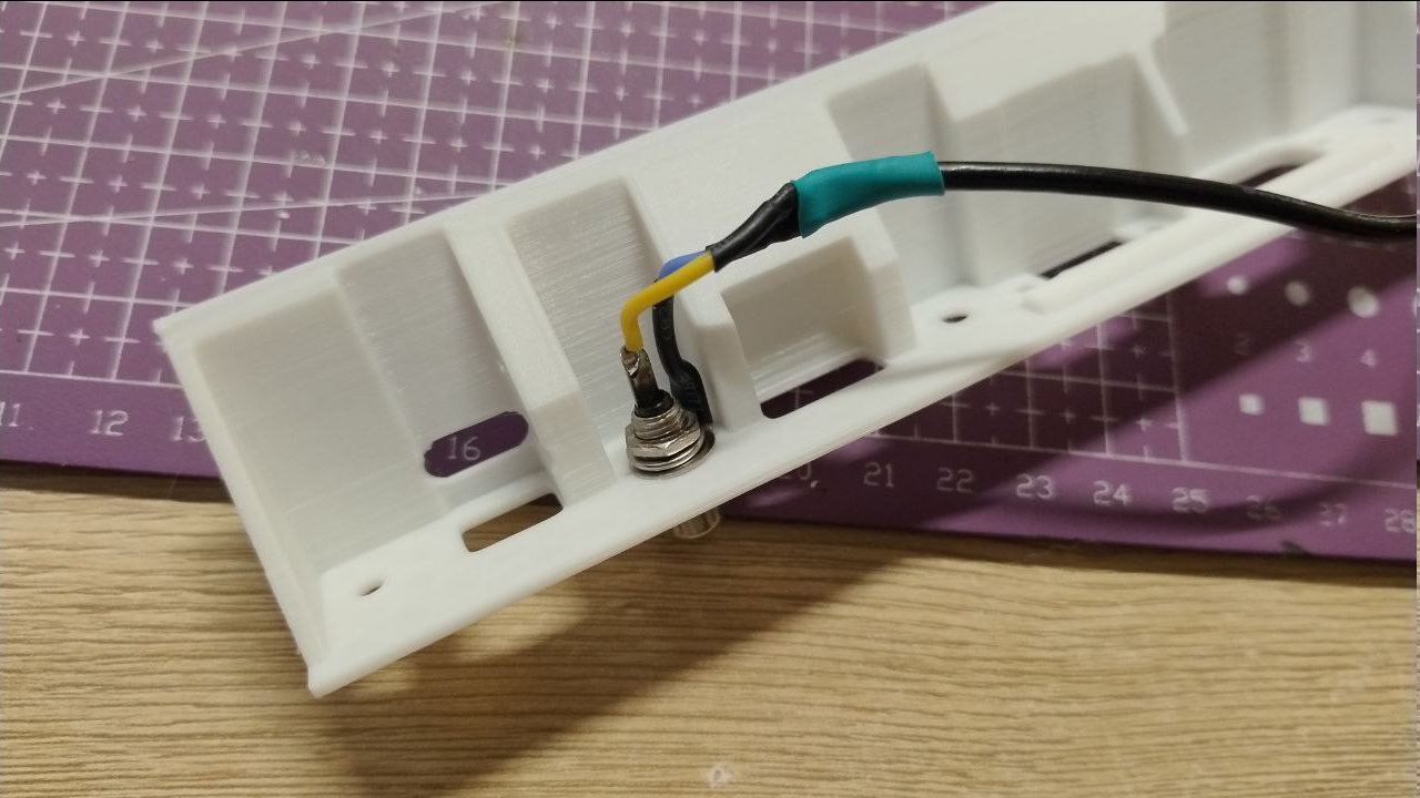
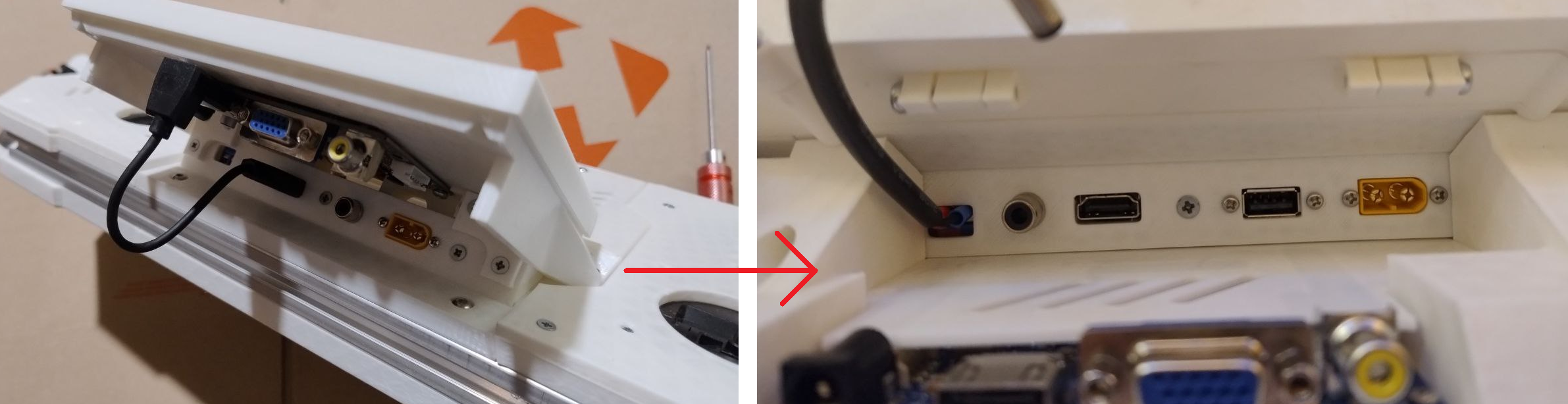
Then it was about the analog video signal chain: Cramming it all together inside, adding power distribution boards: I had to remake the frontal sidepanel that houses frontal connectors. It is now a split part and that eliminates the awkward process of installing or removing connectors for service: Back connector panel also got some attention (again), this time for the sake of ease of connector service. I now do not have to desolder or cut anything, just pass the grounding ring and the nut through the slots and fasten everything up: Since I have to also connect stuff to RPi, these things were made. Later i've added some JST connectors: Trying to put everything inside for tests: And it mostly works. Except that UVC issue and multiplexer behaves funny when second signal is connected - probably due to some overshoots.
Now i can write a proper firmware for input processor, but first it is paramount to move that analog video chain onto a separate PCB because i really do not dig how ugly it all looks when packed.
Some eRr Gee Bee action to make things fresh. Everything else below the break.
---------- more ----------
Small stuff first: aux screen connector panel was rearranged a bit to fit a USB to both provide 5v power and signalling to all the accessories that can be mounted on that screen. In hopes that it will be enough.
The boards are here. Some of them. I completely forgot about axis trim groups and will order them later with another thing I will mention below. Here they are in different state of being assembled: Putting together transmitter connector, I was a bit nervous because I had no idea if everything was done right position wise, but in the end it all fits together after a dance or two:
Still no idea if it works though. Interface distances are much longer than i'd like but what can you do - I iterate more than contemplate at this point.
And that said "iteration over contemplation" brought in an oversight. Turns out I completely forgot about adding actual holes over "documented" circles that supposed to mark where they should be. Oh well, got an order above anyway and work can be split i guess. Life is kind of too short to drill it by hand. Some case changes. This left case part was kinda boring so it was spiced up a bit with a WS2812 array window and a mounting point for a pushbutton with flip up cover. Magnets included!.
And here how it looks from the inside: Printing new framing was surprisingly hard, because new panels added a lot of holes in them and it only means more walls and small fill polygons on bottom and top layers, and that, in turns, adds a ton of frequent retractions - this contributes to heat creep and hotend clogs much, much more often than i'd consider normal. Even when it prints in 17C environment.
I've switched to FreeCAD v1.0 and to be honest - I'm not entirely on board with many changes. Some are welcomed, other are a mixed bag. Constraint solver seems to have become much smarter, but overall perfomance and it's proclivity to do recalculations even on a newly opened project that consists only of historyless bodies leave a new patch to be desired. And i'm not even talking about it's inability to migrate exact projects that i was working on with v0.21 - it sees weird feature attachment points and dies, bringing the project with it. I guess i can start wiring stuff now and bring up HID functionality for that basic input action?
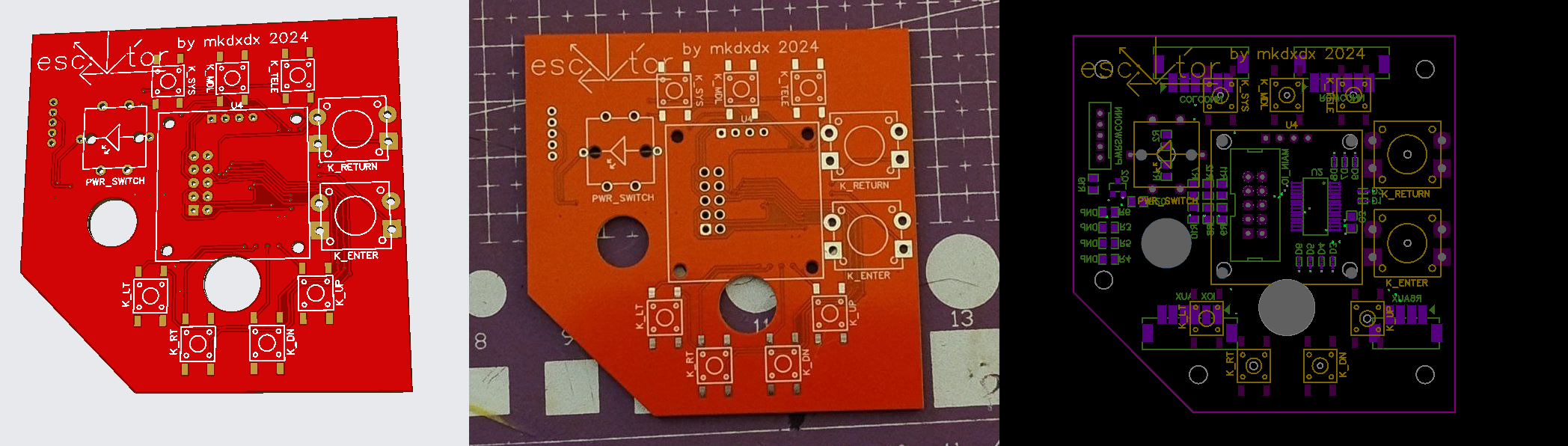
After couple of days in EasyEDA, I've got this which is now in production.
Parts are hopefully to arrive roughly when boards do and so assembly waits for a later day, probably next year because non-building stuff does get in the way and I'm not even sure what the blackout situation will look like in a week - lights are already off twice or thrice during the day for several hours after missile attacks on our energy infrastructure.
Schematic mostly repeats part of Radiomaster TX16 reverse effort, check them out, plenty of info, and now after boards are on the way I kind of think I'm sleepwalking into a disaster - there is a high chance that tristate switches are not actual two switches but rather a voltage divider sampled by ADC, whereas my implementation uses a ton of switches hooked up to IO expander in a matrix fashion.
Some changes are cosmetic, but down under most of them - a couple of sleepless days plus some refactoring.
---------- more ----------
First change might not be easy to notice is that stick openings are now rectangular. I think it plays to everything else rectangular on the build.
Right panel got it's layout finished and it now houses a controller for all things RC, will probably run a custom build of EdgeTX, resources allowing. At least it does not feature a gap anymore.
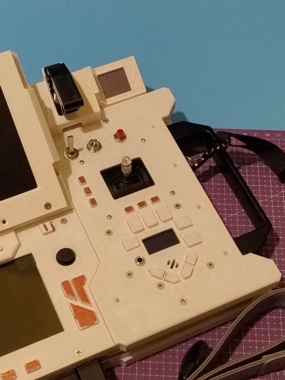
Left panel too got it's settling. It now has another button area that will house what can be described as HID Processor - that thing will feature some macro buttons, some indicators with epoxy diffusion and it will all be also wired to buttons around primary screen so to control what these do, like arrows, paging, mouse cursor etc. The levers are gone - I do not like how janky they are, I do not like how unstandartizing they are, in favor of more slider switches. To offset the loss of visual "stuff" that happens there, analog multiplexer control (which is a servo tester in disguise) got an arrow styled knob with magnetic hints under it - when knob passes over certain spots, it gives a gentle feedback and sets over the spot if you release it. Not my idea but i honestly forgot who posted about it recently and where. The secondary screen panel got a little bit of tidying, but not much. I've swapped power wire for a proper angled connector one - as a meditation to begin my new work week for this project. For some reason I've never posted a pic of how glorious interfacing corner looks when everything is connected: And screens finally got their button caps so they are not looking like broken teeth anymore.
I think she is ready for some PCB design and maybe I will come up with a painting pattern in nearest future.
If that looks like a mess - that's because it is and it's that way because it's in the middle of a panel/frame swap (and new panel is right in the center of the frame).
---------- more ----------
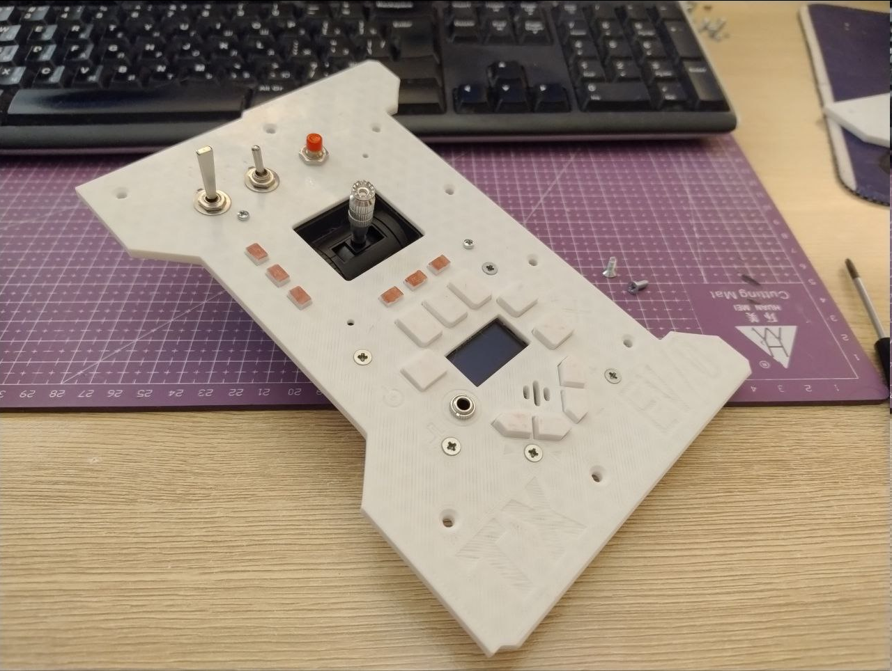
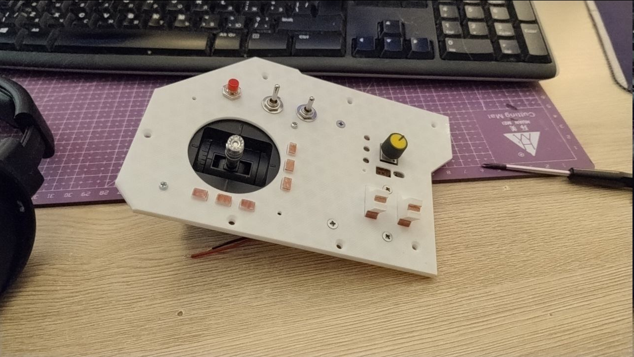
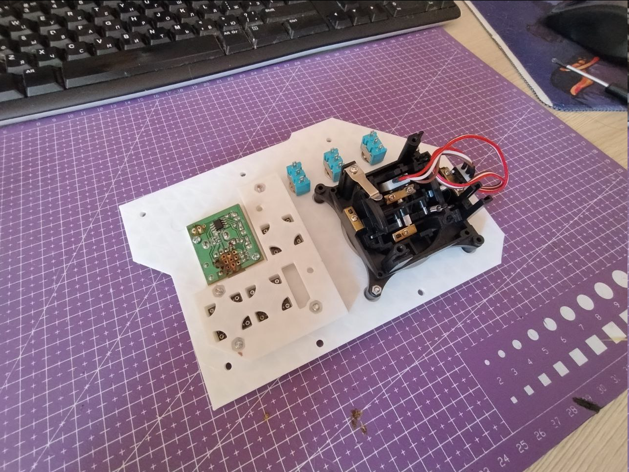
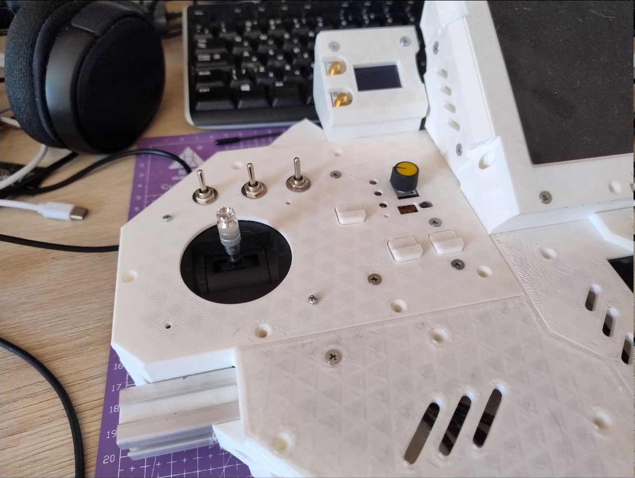
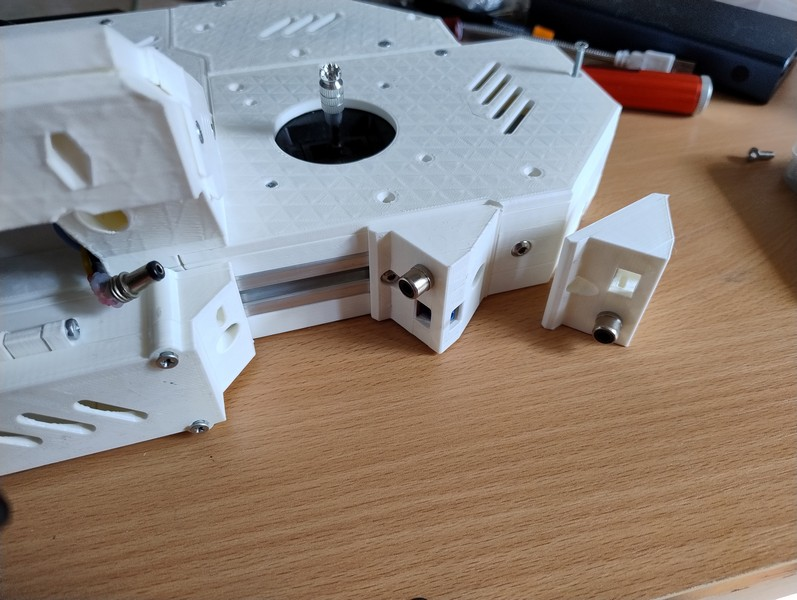
So, new panels - one is for frame part, second is the front one. It now features openings for a thumbstick, mouse buttons, d-pad, a set of few auxiliaries and also two slider power switches.
And here how it looks more or less assembled:
Button pushers are actually plastic dummies because i will bother with adding proper contacts later, but switches and thumbstick are functional, yet are not connected anywhere.
As for the weird language those rightmost buttons speak - the idea is to have "inverted mouse" arrangement, where index/middle finger operates a thumbstick (and it's hard, that's why it's called a thumbstick, duh), while thumb clicks on what maps to left mouse button. Two other will be interchangeable and map to right/middle mouse buttons. We'll see how it plays out ergonomically.
I've got this nagging feeling after that last update - buttons are boring! So I'm gonna have them and something else too!
---------- more ----------
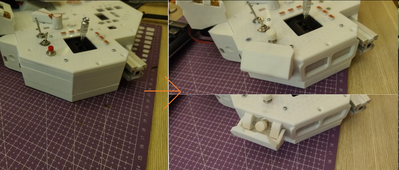
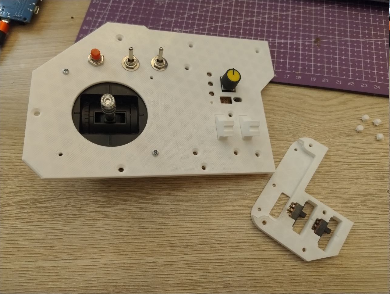
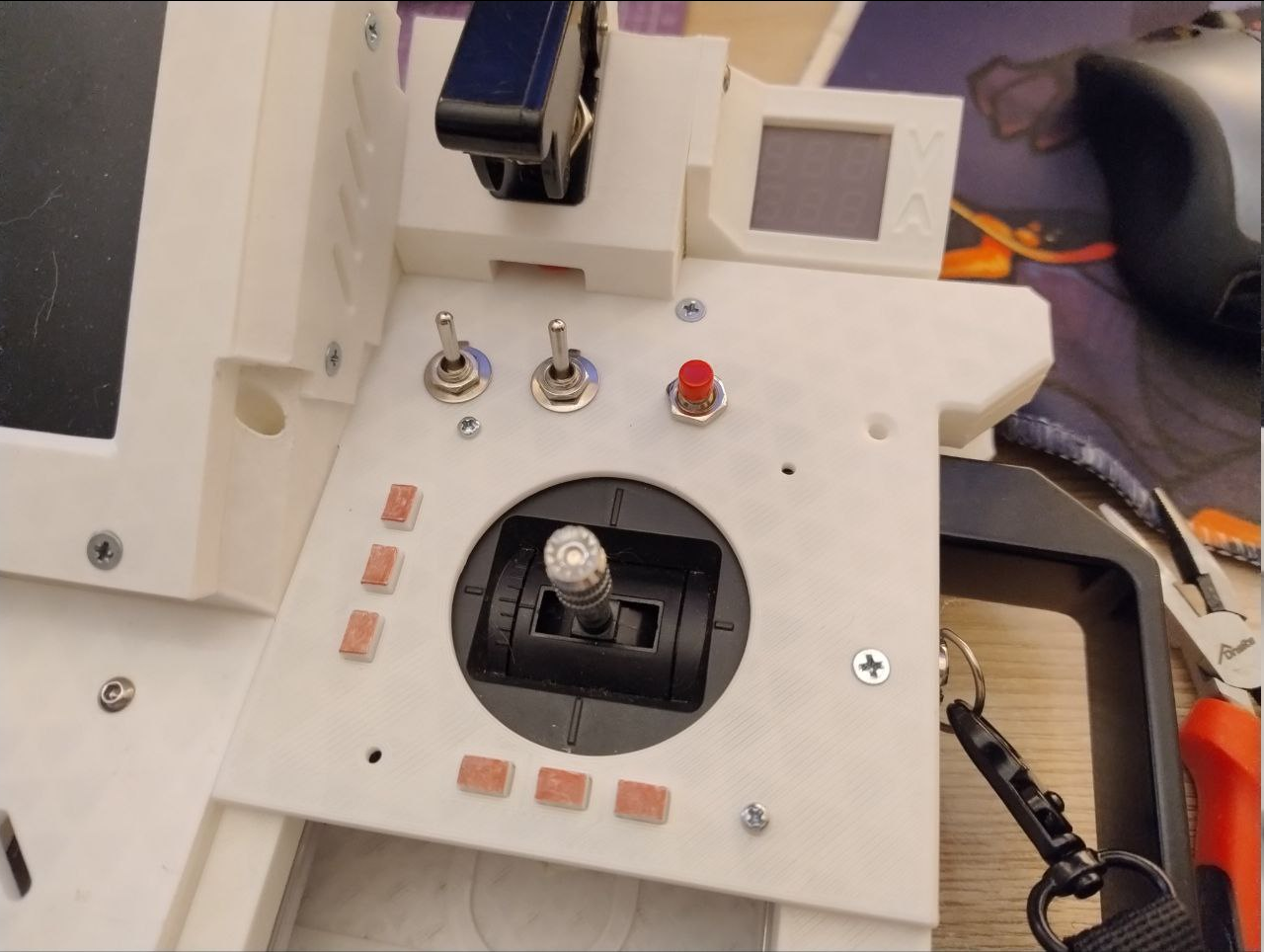
Panel was remade to house these little custom levers that actuate slide switches for.. stuff I'm going to figure out later. Kinda big now but at least it's more interesting that way, right? With some effort it's also possible to cram in a LED inside to display it's status but that is for later.
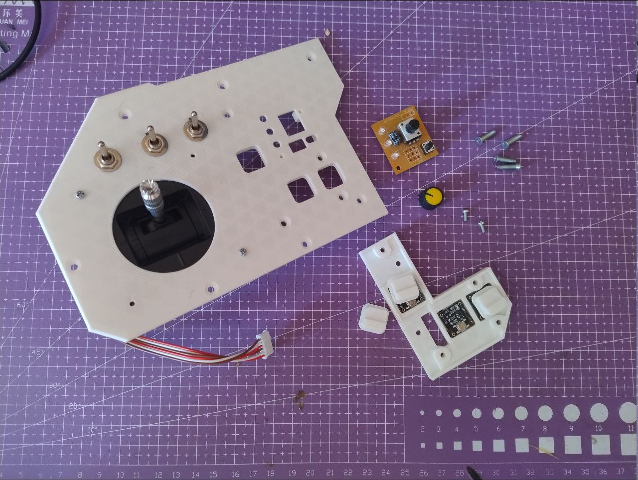
Next comes - I've decided to install trims (or trimming controls). For uninitiated - these are to sort of offset current vehicle controls (add a little constant value for stick axes or channels for different purposed). Initially these were supposed to be made out of readily available button boards for bluetooth speaker media controls. But it turned out they are too big to fit everywhere I've wanted them to.
So, instead, I've designed these little harnesses around each stick to house little flat tactile buttons to save on footprint and also fit them as close to stick itself as possible - as a user hint what these do. And just like that, I've got myself some trims which also add some details to otherwise offensively white case.
Sort of a keep-alive log about trying to figure out how to build on top of what's already present.
---------- more ----------
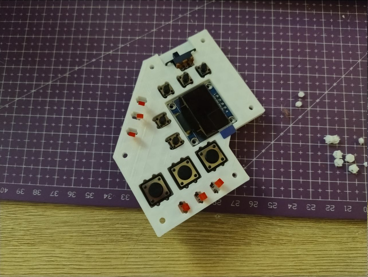
So, it's time to populate front panel with buttons and not break anything in the process.
Turns out one cannot imagine every possibility of a part of a project and hold everything in one's head at the same time - one have to actually "just wing it" sometims in order for a viable direction to appear and move on from there.
You can sit there, shuffle buttons and panels in your had all day long, but only one concentrated sitting later you get what works and throw out what does not.
This time buttons should:
Sit over ELRS TX
Not push said ELRS TX out
Do something I've not entirely figured out yet other than control power and maybe something else
Not look boring
And there is also servo tester board that doubles as a control signal generator for video switcher I will add later.
And oh lord how project RESISTS to any change at this point.
^ This is how current iteration of the deck looks if I was to make build instruction. Do those white pieces in the left bottom belong anywhere on the build? The answer is below.
---------- more ----------
Working with extrusion rails can be both blessing and a curse.
It becomes a curse once you have to have a lot of t-nuts that hold some kind of cover and holes must align.
And it sucks when you have to fish out these t-nuts from somewhere where they have just slid. It double sucks if they become pressed against something and won't budge back if you shake the frame in question.
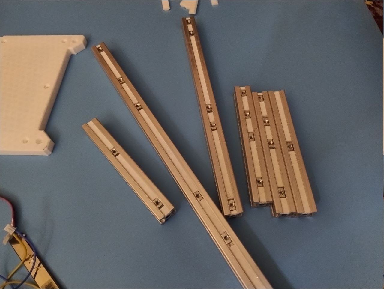
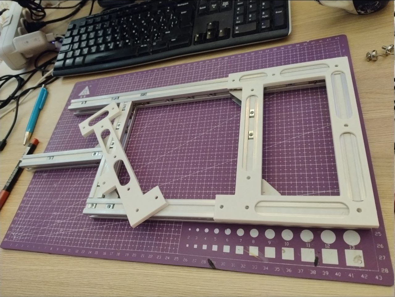
In order to make it suck tad less, I've decided to bet that I will not be changing either cover panels or external accessory mountings and design grove plugs that will fix t-nuts, simultaneously providing some leeway - because t-nuts not necessarily have perfectly centered threading holes. It does require some force to push these down the grove, but that is mostly because my printer has no concept of proper calibration - it's a tool, not a hobby. Another minor thing was to make these little rail-frame-guide things that temporarily go over the frame while it is assembled - to allow angle fasteners to be mounted and, well, fastened. Sadly, it does not solve all assembly problems - I did have to loosen everything, mount back panels and sorta squish the frame until it is properly squared, before tightening everything. But after that, panels come on just flawlessly, without me needing to fish out t-nuts that roll around and hide from me each time I have to run another wire somewhere.
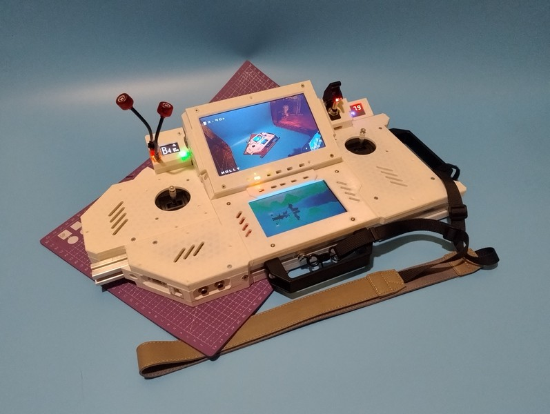
Bonus content: this is how it may look in a HMD-centered setup (no HMD yet), when top monitor is removed - there are plenty of stuff to connect HMD in question both to signal (HDMI and analog) and power.
ELRS TX and throttle stick positions has been switched. Probably needs more adjustments for comfortable throttling action, maybe some cushioning around and symmetry is now officially ruined but i guess that's how it's gonna be from now on.
There are people who tried to reload things like if they are scifi weapons (Kommander Karl style) and those who aren't entirely honest about it.
A lot of things happened since the last log - some progress and a detour in the middle.
So I was gaining some momentum in this project and then Cyberdeck Cafe has bitten me with this idea to share with people how I go about designing things in FreeCAD - throwing me out of the saddle for two weeks.
It has ended so bad, I came up with an actual haphazard writeup of how to model your own portable terminal in FreeCAD from concept, to a production-ready handheld, including my own, 14th in a row explanation of what it the most problematic thing in FreeCAD and how to trick around it.
If you ever wanted to either push through a wall of semitechnical text or just curious how to make things in this software, here is an attention attracting picture of the result:And link to tutorial: https://bitbucket.org/mkdxdx/howtobuildashelf/
Other updates: rail-mounted battery pack, VRX mount, primary circuit breaker, new monitor and ELRS micro TX caddy - as usual, below the break.
---------- more ----------
So, a replacement monitor has arrived instead of the one I've almost wasted previously. This one has different scaler board so some fixes had to be applied, and good thing is - it has same button board as the bottom monitor, so now front panel looks a bit slicker:
Some new stuff immediately shows up, so, here it comes in no particular order.
Circuit breaker
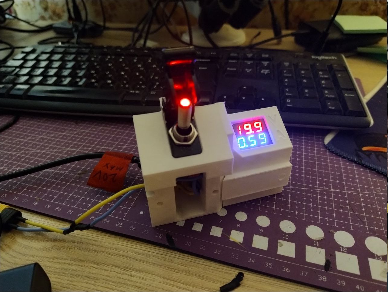
The deck now has primary power ingress module that accepts XT60, runs power through ASW-07D "helicopter" toggle switch, optionally (it is also modular in itself) continues running it via a 10A automotive fuse and volt-amperemeter module and then gives you another XT60 to plug it into the deck's main power input. I had to iterate it at least a couple of times, first it was monolithic, then it was split in two halves to ease printing and simplify the design itself, and then it turned out that these round fuse holders aren't very ergonomic to install in cramped spaces, because their nut is not that easy to affix when tightening and they are very, very brittle if you wanna hold it with pliers So I've went with this DC automotive fuse holder with a cap that mounts with two screws and called it a day: I also had to wait for new meter to arrive because I wasted the first one when miswired it's current measuring connector.
VRX caddy
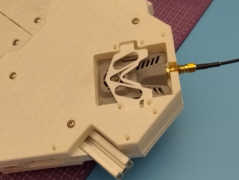
Next is the VRX holder/caddy/carrier thing, which also suffered some iterations before settling on something digestable. Initially it was almost monolithic, but then I've split it into a holder and signal/power connector group: And it's at this point I've realized how wasteful these redesigns are, because without proper forethought, minuscule changes make you dish out tons of material just to discard the next iteration (note how left and right assemblies have different rims - they were reprinted just for that small change) ELRS TX micro JR bay carrier
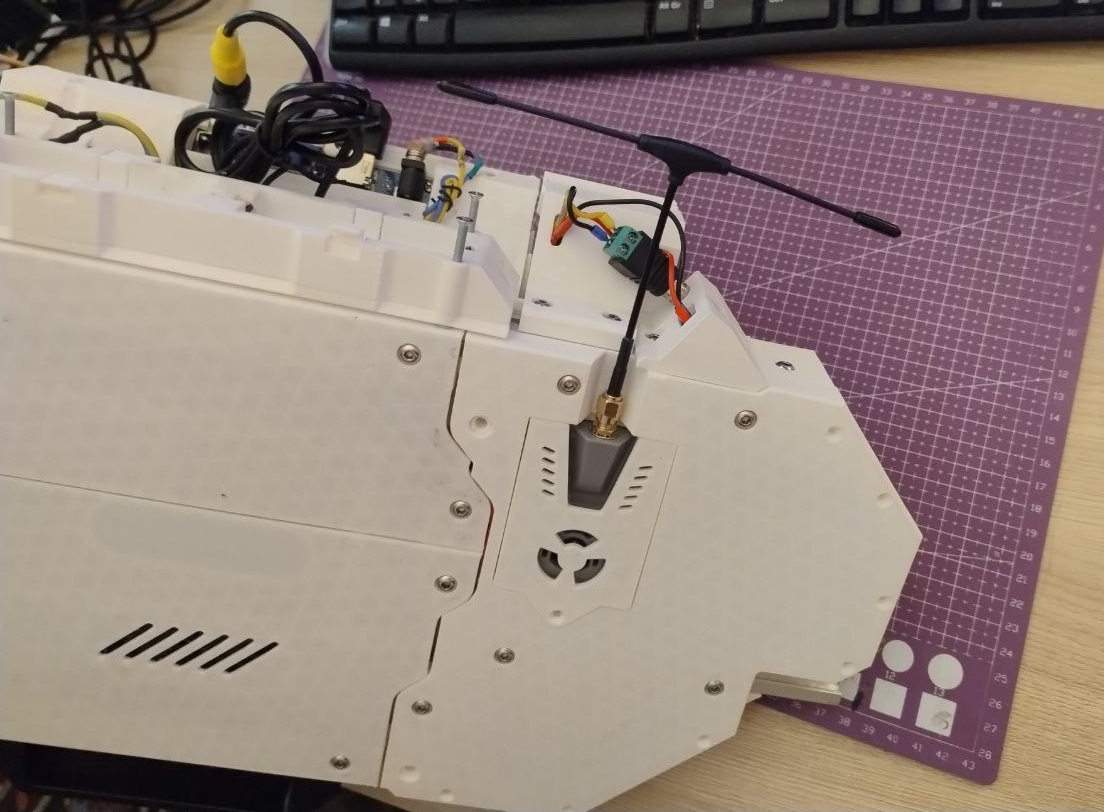
Honestly I have no idea what's the correct name for this module format because it has like 2 or 3 different names, but I can now mount the thing into one of the bottom panels and have it's antenna sticking out when in operation. It also allows the module to breathe and all - but eventually it will be moved under VRX to allow for left stick to be moved even further to the left. Rail mounted 2S Li-Ion 26650 battery pack
I've learned a lesson from previous build that having internal batteries does not allow you to do much so it is now external and mounted on aluminum frame in the back. It was iterated at least twice too, first being balls to the wall DIY (because even contacts were made of some tin cutouts) and second one finally featuring some readily available springy battery contacts plus some levers for cool reload animations, like it was shown above to grab your attention. Balance leads included.
When most of the things connected, the backside looks much more busy than what it does, but I will probably come up with some kind of compact wiring solution to this, hopefully without compromises on functionality. But that should be it for now! It moves and can't be more happy.
 mkdxdx
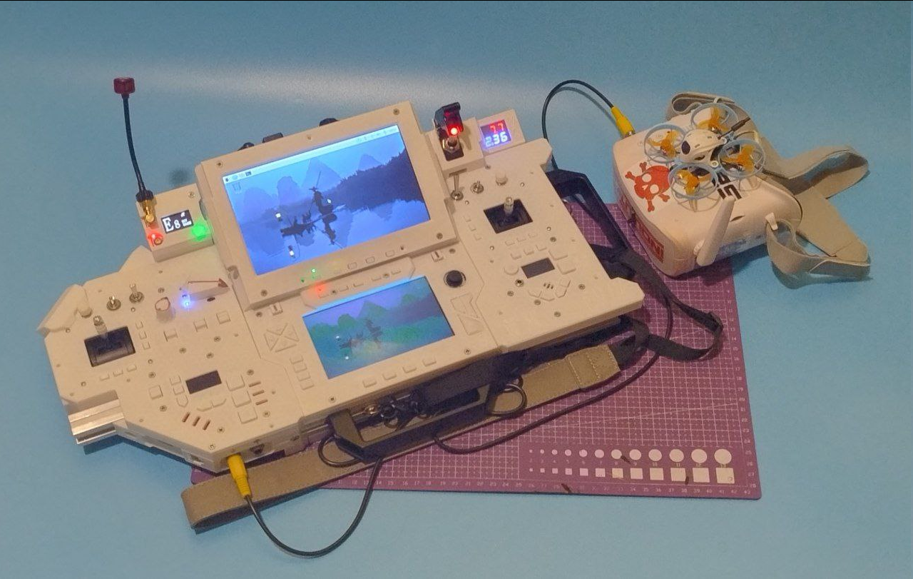 It's a bit disappointing when it took a lot of time to do things but these things sort of can't be shown clearly because they are not visually significant and quite messy.
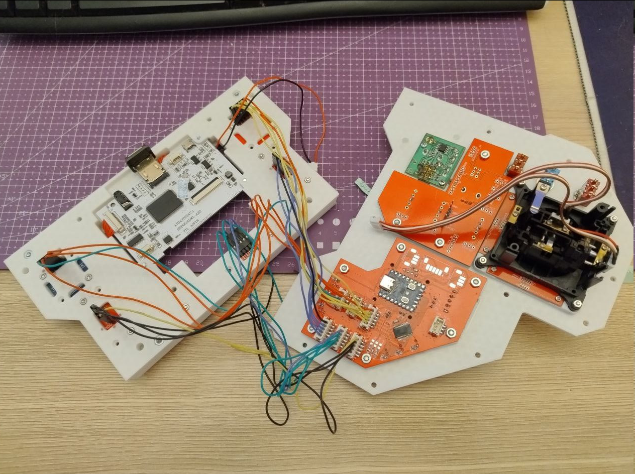 No proper firmware for the input processor yet, but i did a little test that schematic is correct and soldering was done properly.
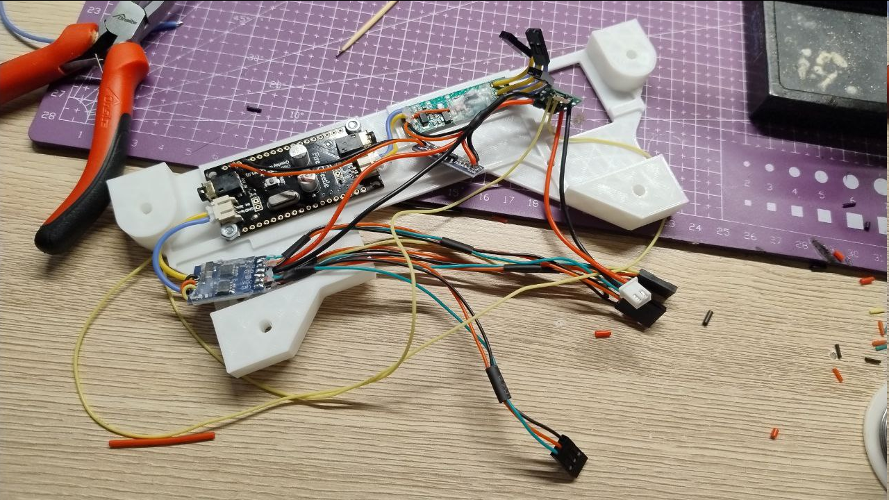 Cramming it all together inside, adding power distribution boards:
 I had to remake the frontal sidepanel that houses frontal connectors. It is now a split part and that eliminates the awkward process of installing or removing connectors for service:
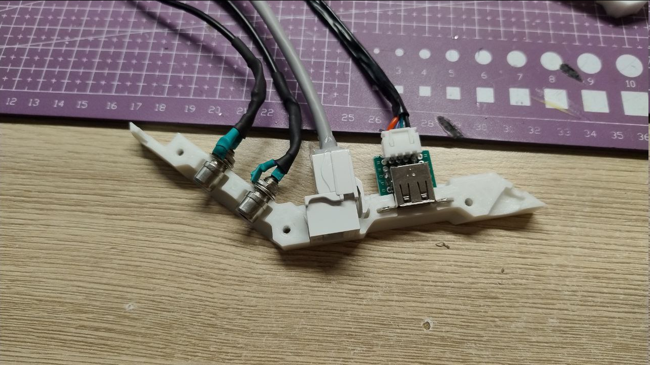
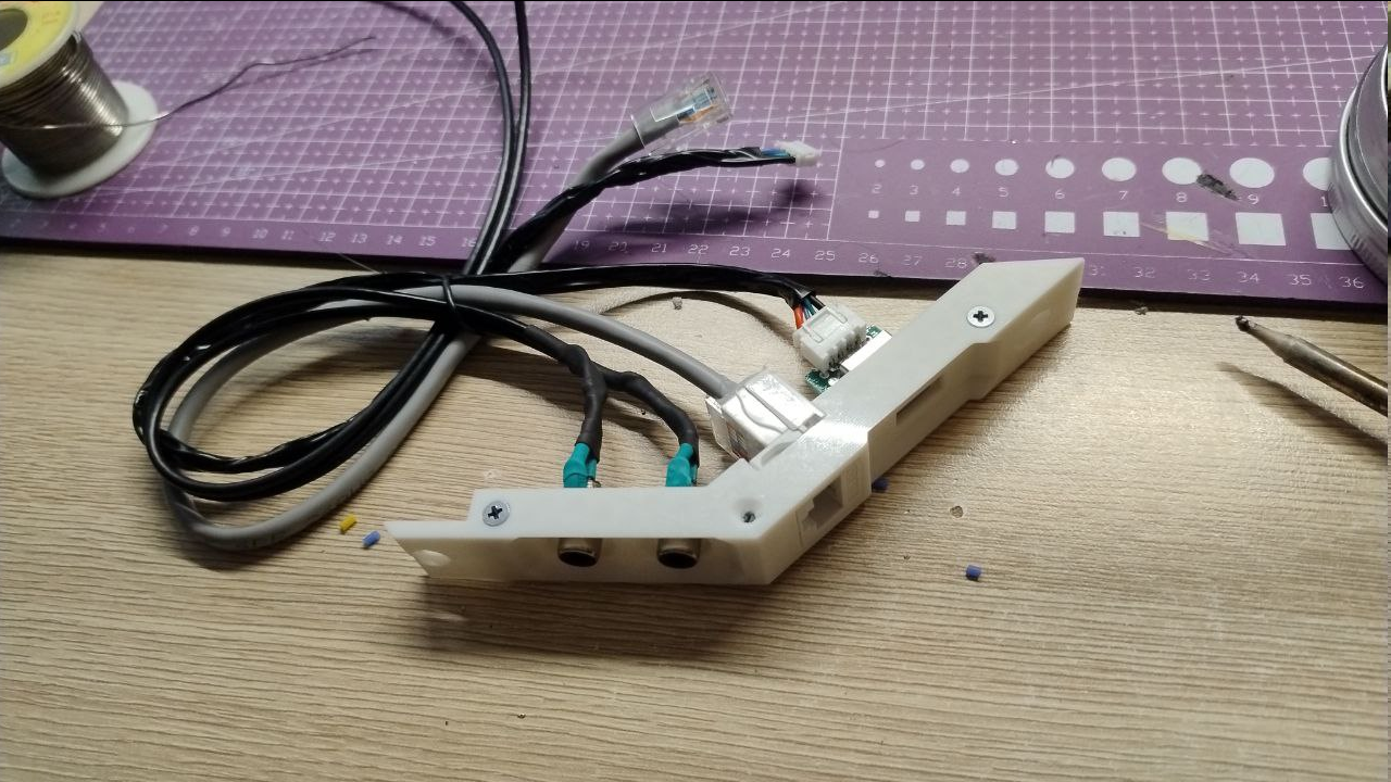 Back connector panel also got some attention (again), this time for the sake of ease of connector service. I now do not have to desolder or cut anything, just pass the grounding ring and the nut through the slots and fasten everything up:
 Since I have to also connect stuff to RPi, these things were made. Later i've added some JST connectors:
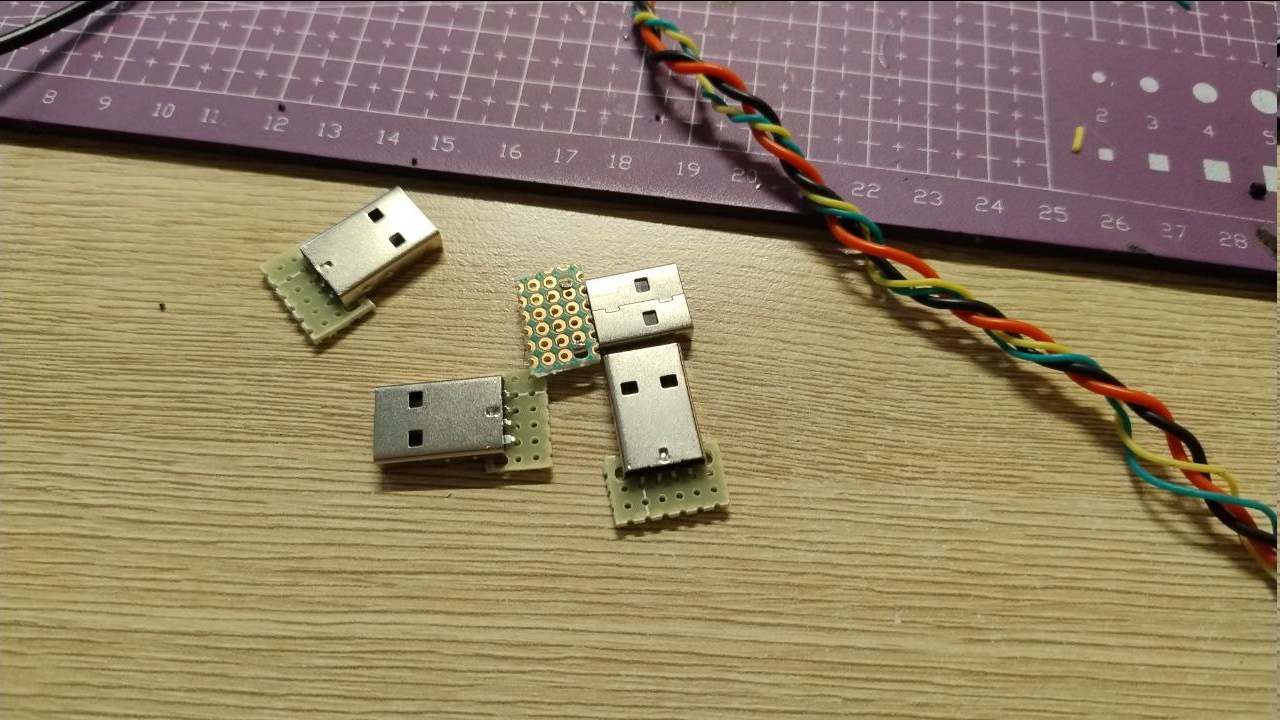 Trying to put everything inside for tests:
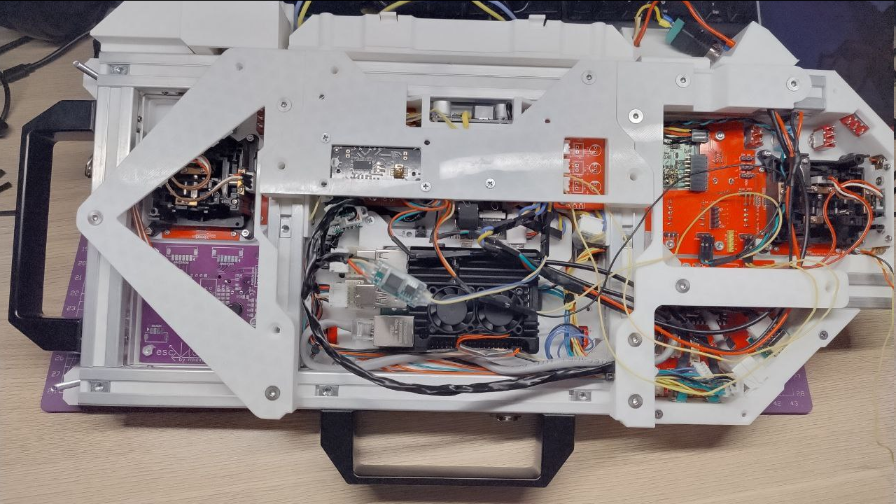 And it mostly works. Except that UVC issue and multiplexer behaves funny when second signal is connected - probably due to some overshoots.
 The boards are here. Some of them. I completely forgot about axis trim groups and will order them later with another thing I will mention below. Here they are in different state of being assembled:
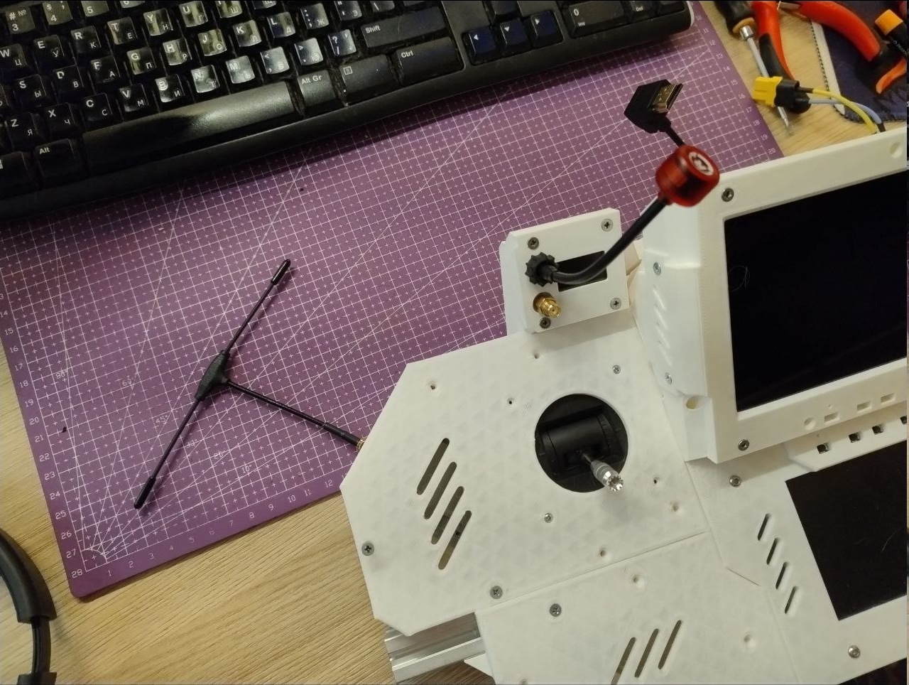
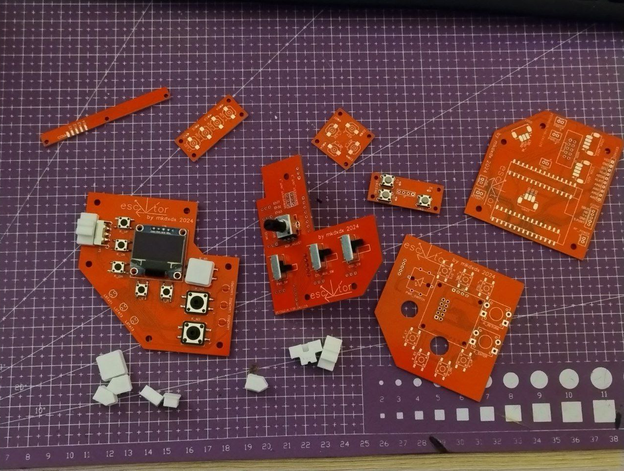 Putting together transmitter connector, I was a bit nervous because I had no idea if everything was done right position wise, but in the end it all fits together after a dance or two:
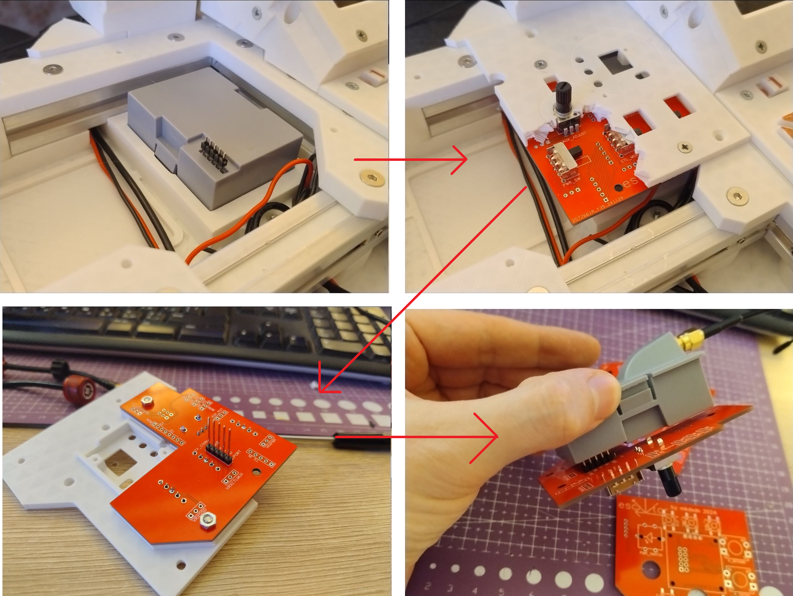
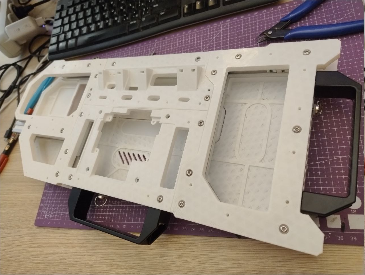
 And here how it looks from the inside:
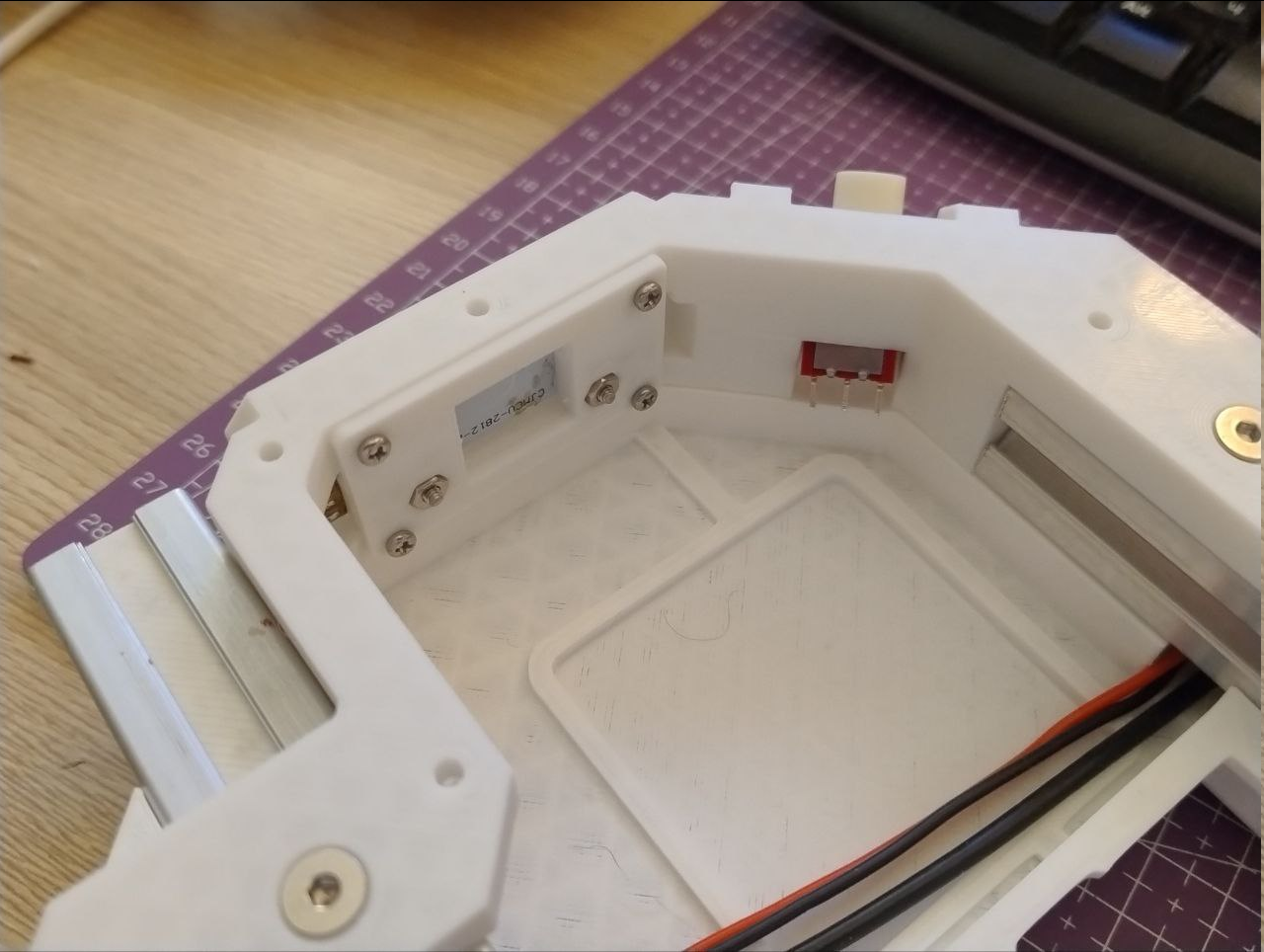 Printing new framing was surprisingly hard, because new panels added a lot of holes in them and it only means more walls and small fill polygons on bottom and top layers, and that, in turns, adds a ton of frequent retractions - this contributes to heat creep and hotend clogs much, much more often than i'd consider normal. Even when it prints in 17C environment.
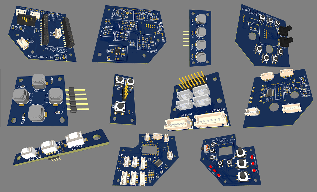
 Some changes are cosmetic, but down under most of them - a couple of sleepless days plus some refactoring.
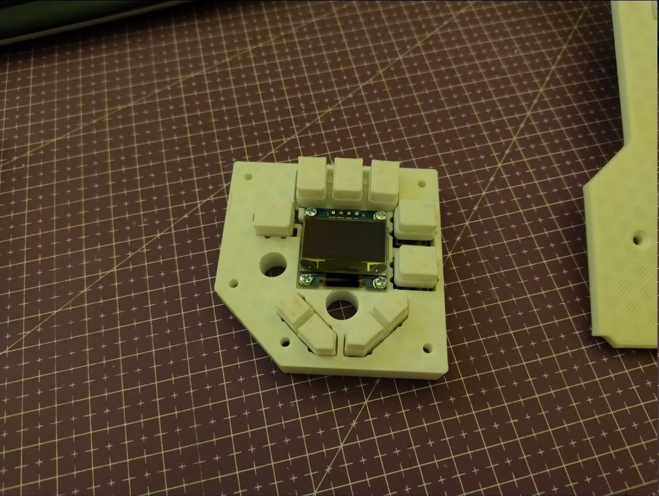
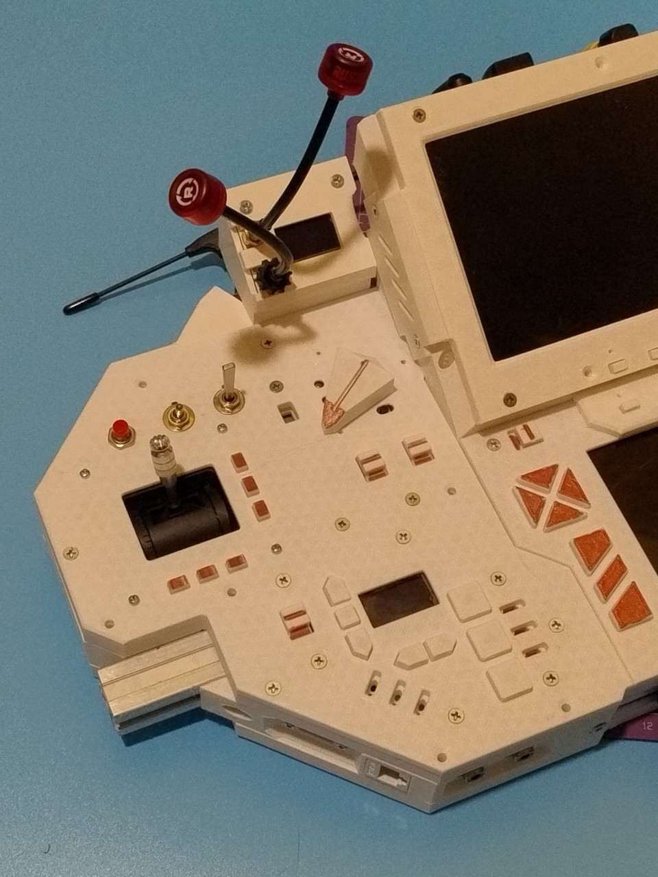
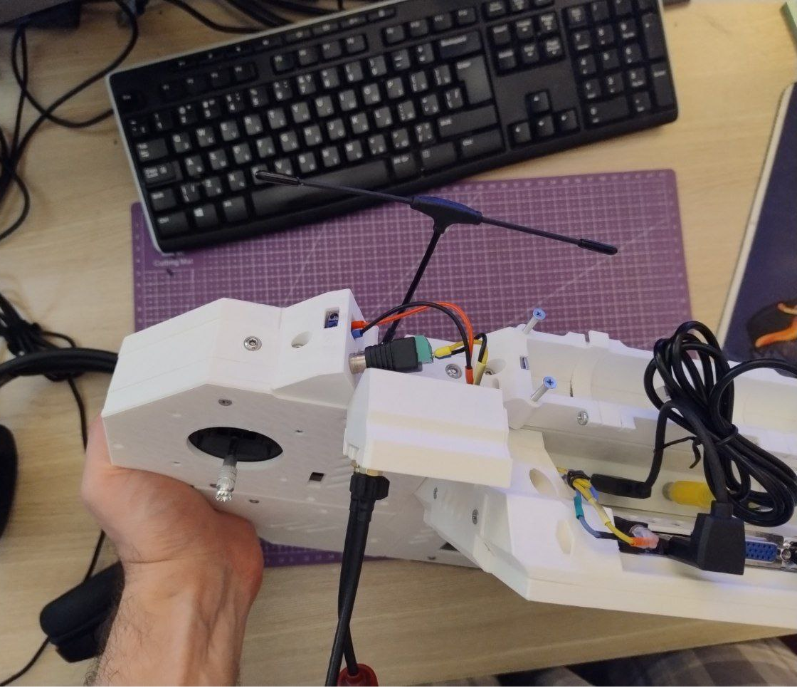
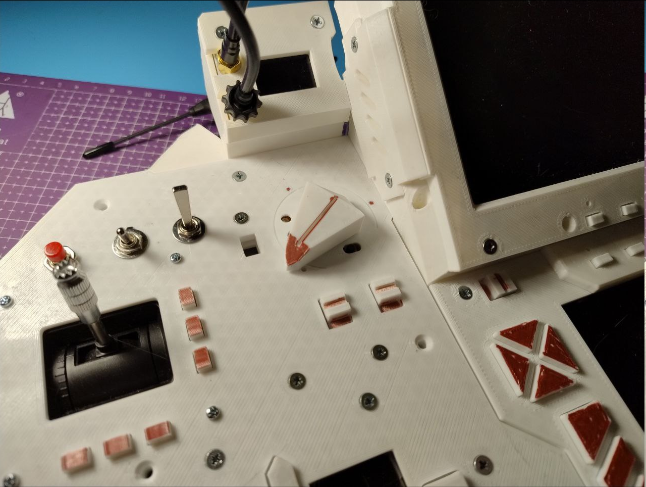 The secondary screen panel got a little bit of tidying, but not much. I've swapped power wire for a proper angled connector one - as a meditation to begin my new work week for this project.
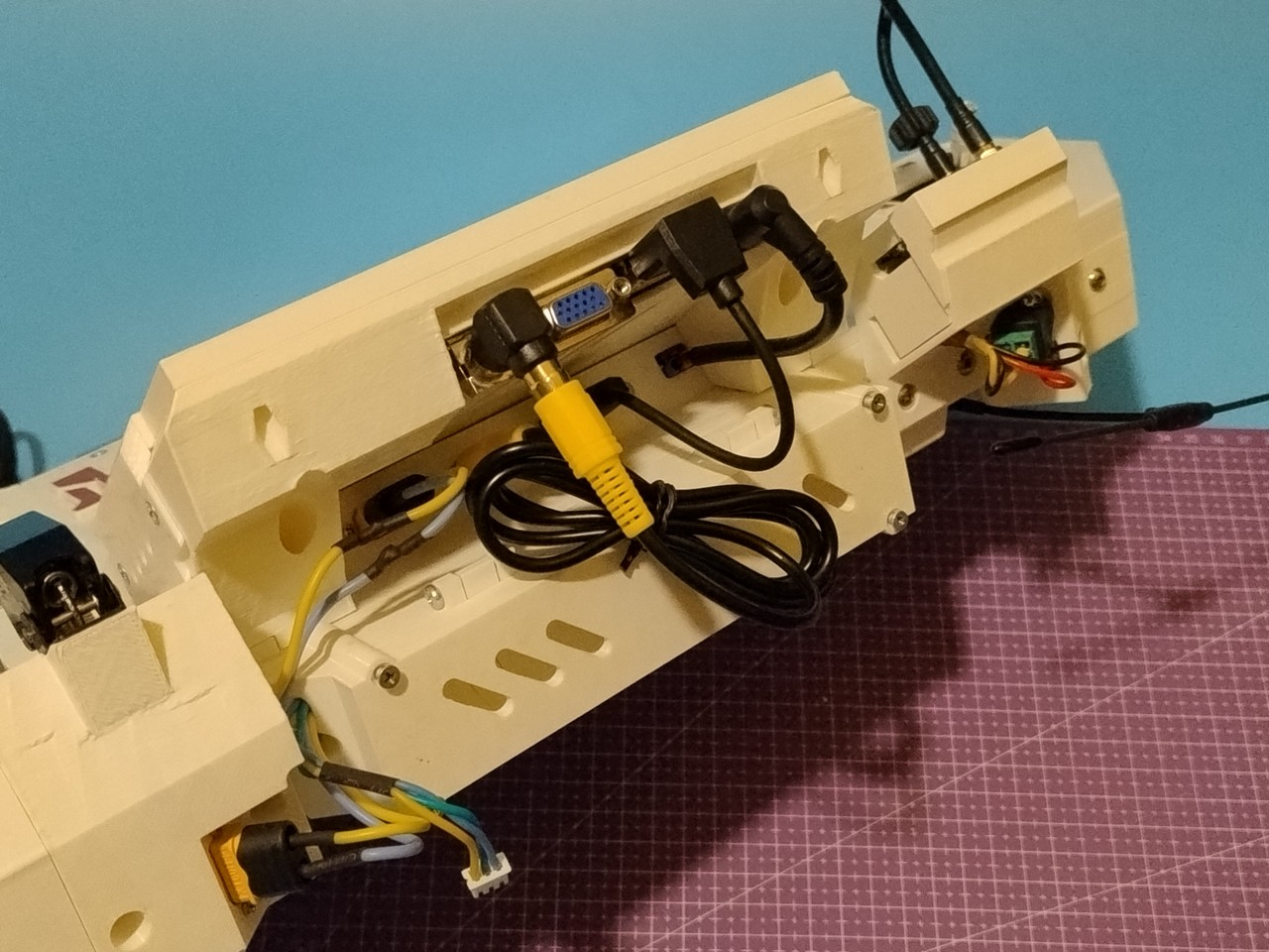 For some reason I've never posted a pic of how glorious interfacing corner looks when everything is connected:
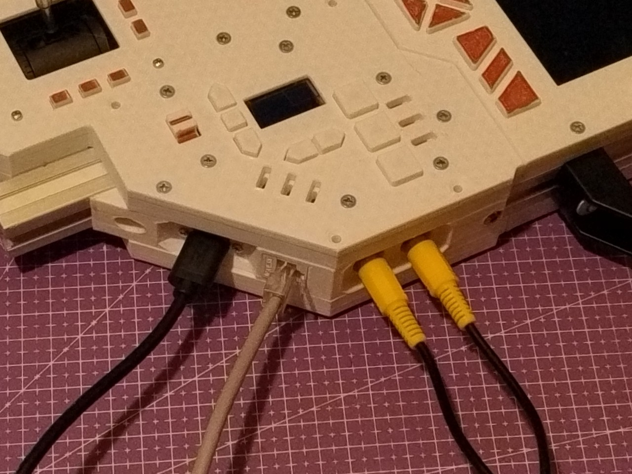
 If that looks like a mess - that's because it is and it's that way because it's in the middle of a panel/frame swap (and new panel is right in the center of the frame).
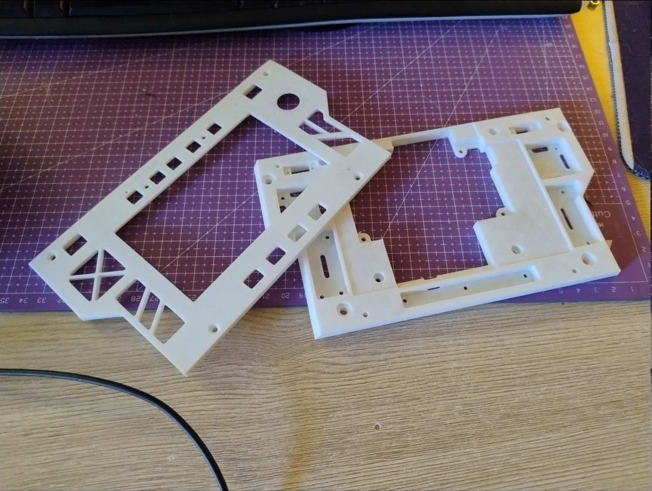 So, new panels - one is for frame part, second is the front one.
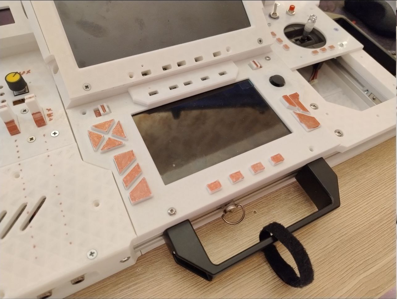 Button pushers are actually plastic dummies because i will bother with adding proper contacts later, but switches and thumbstick are functional, yet are not connected anywhere.
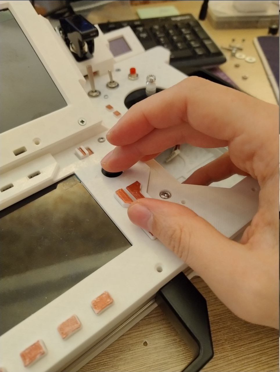
 I've got this nagging feeling after that last update - buttons are boring! So I'm gonna have them and something else too!
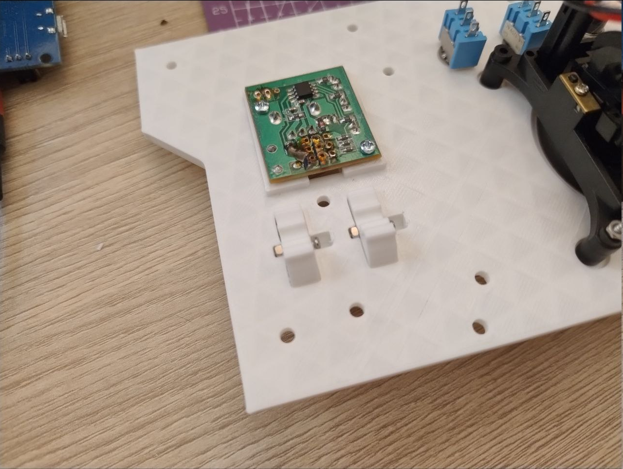
 Next comes - I've decided to install trims (or trimming controls).
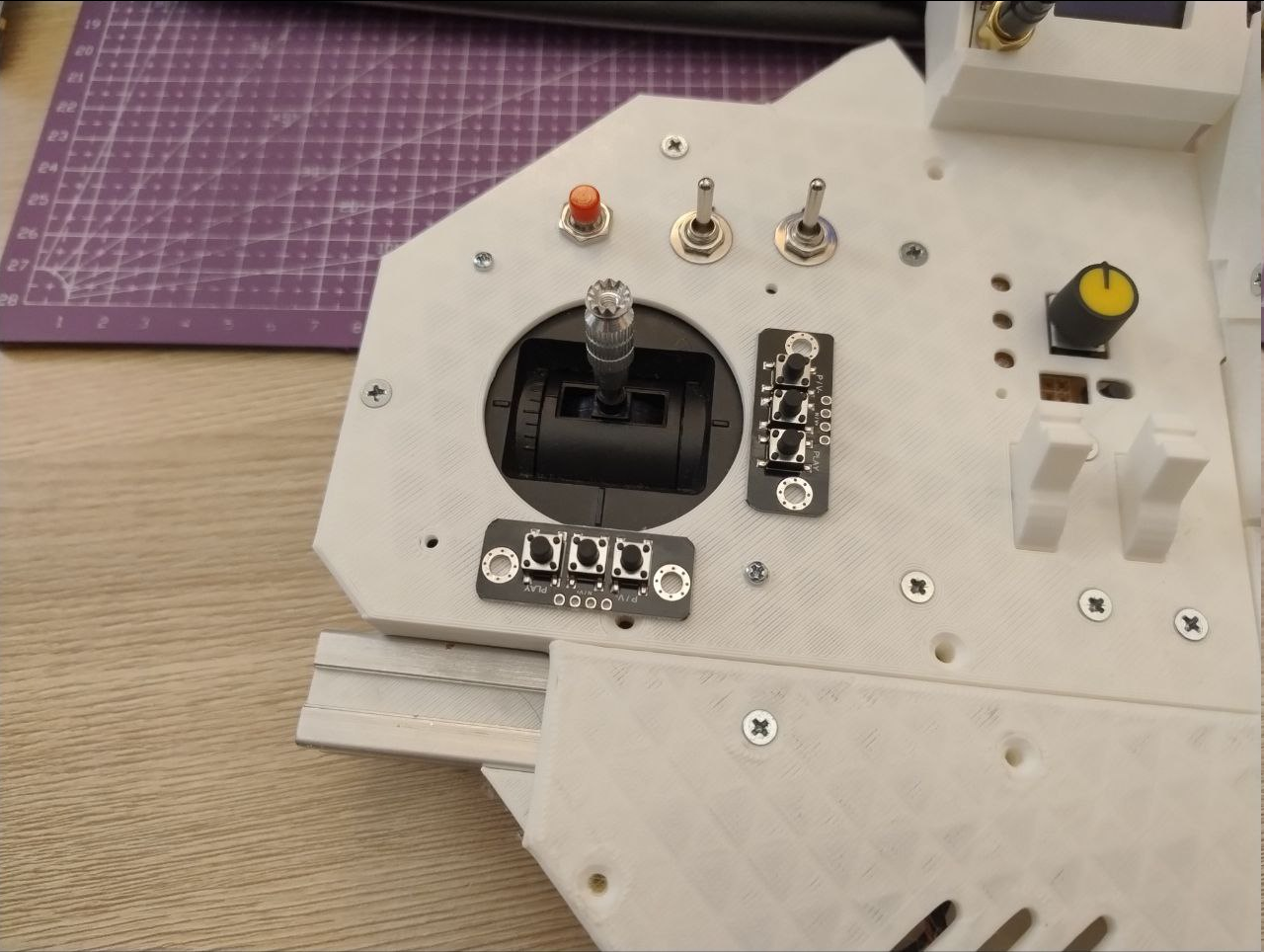 So, instead, I've designed these little harnesses around each stick to house little flat tactile buttons to save on footprint and also fit them as close to stick itself as possible - as a user hint what these do.
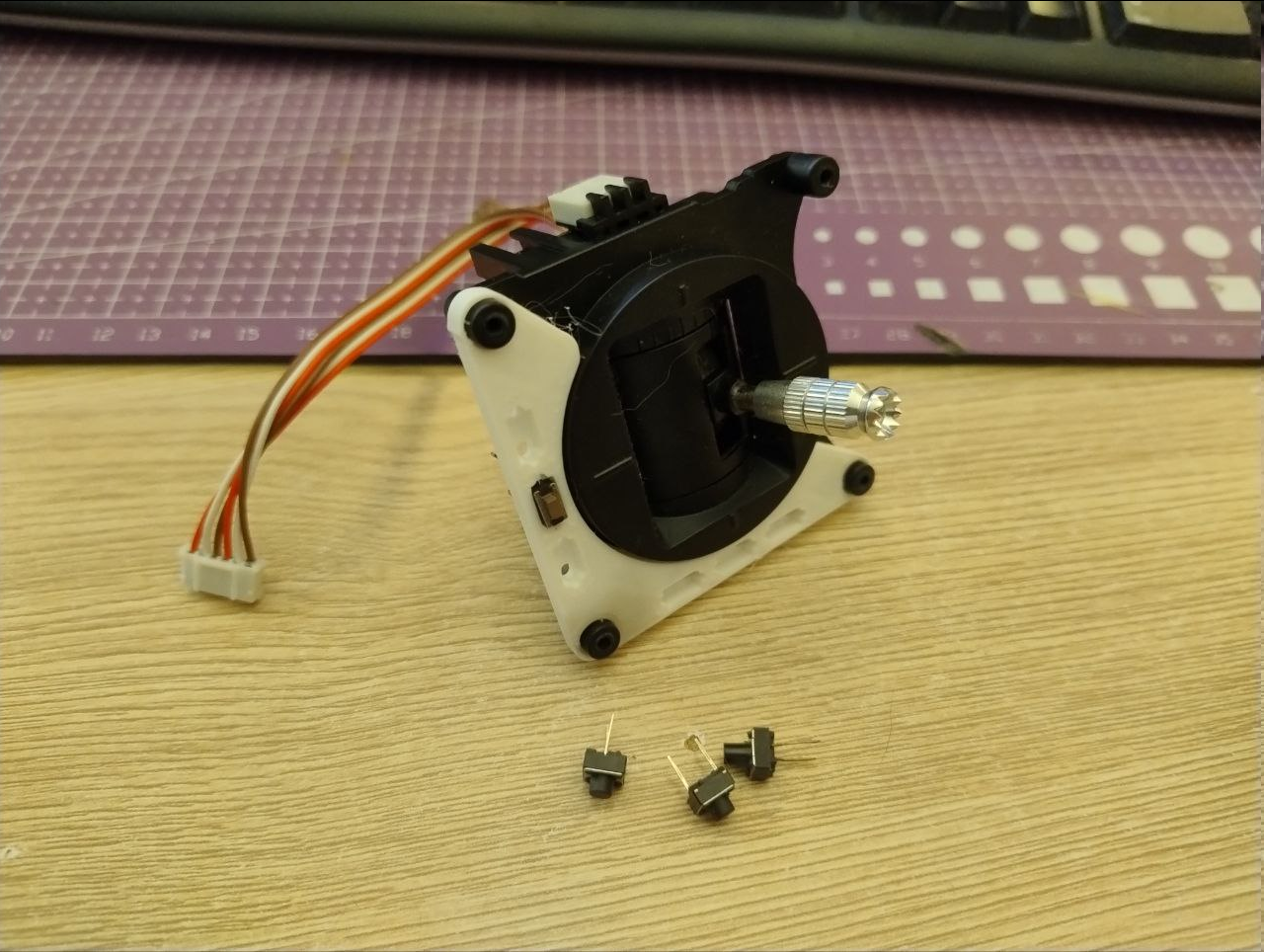 And just like that, I've got myself some trims which also add some details to otherwise offensively white case.
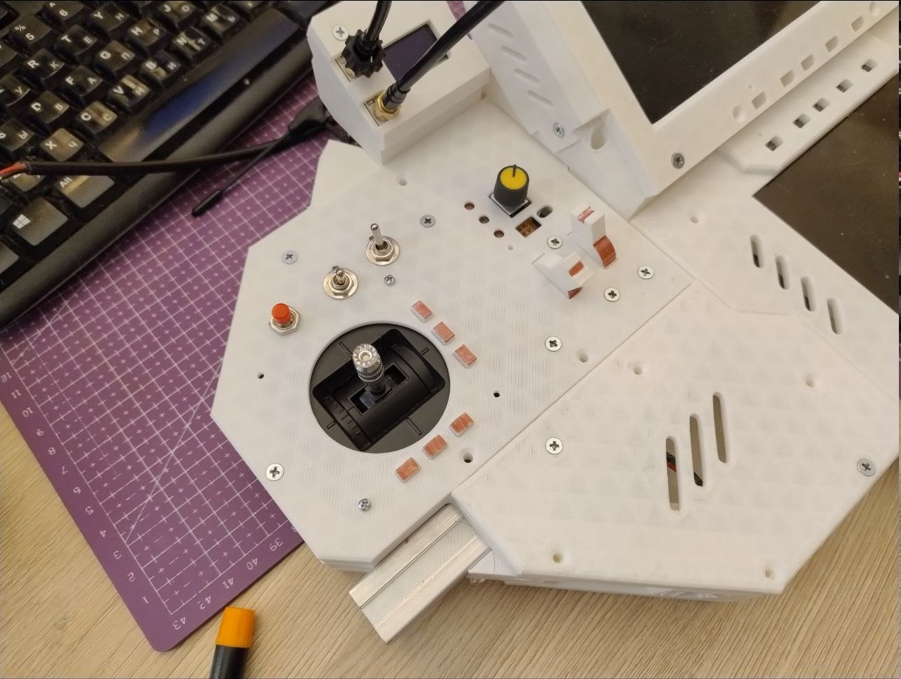
 Sort of a keep-alive log about trying to figure out how to build on top of what's already present.
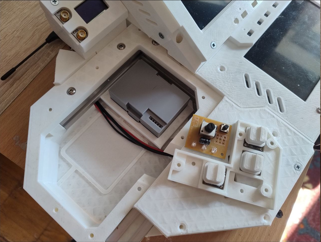
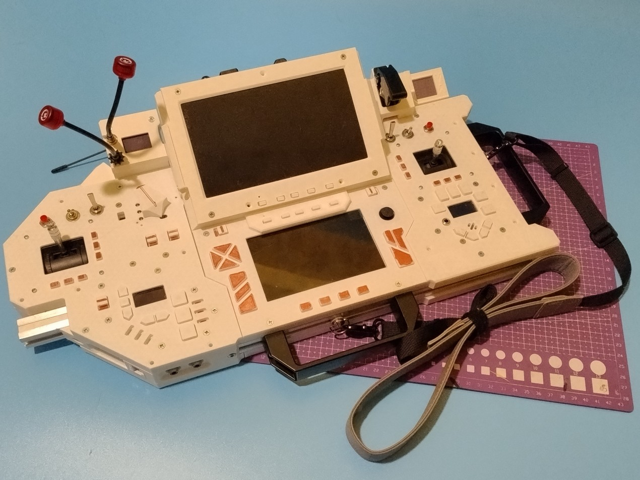
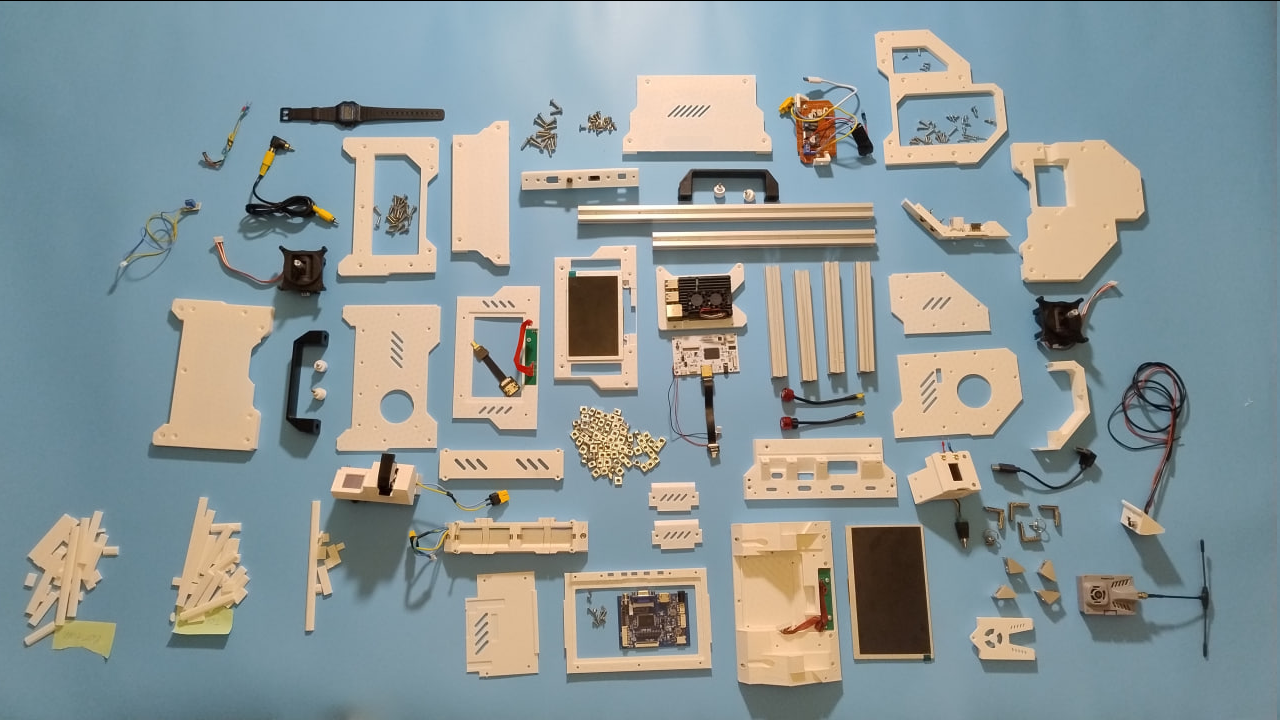 ^ This is how current iteration of the deck looks if I was to make build instruction.
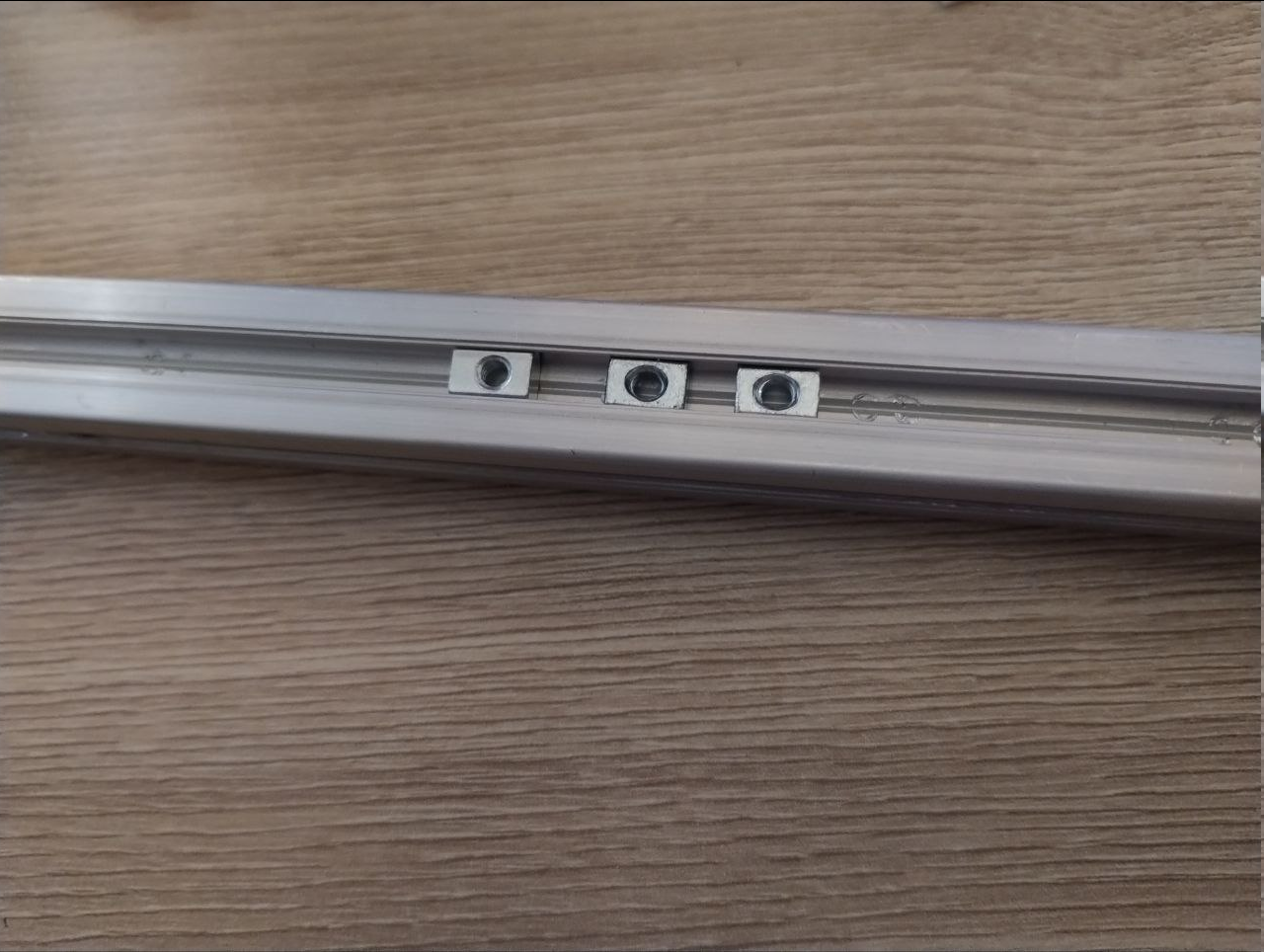 In order to make it suck tad less, I've decided to bet that I will not be changing either cover panels or external accessory mountings and design grove plugs that will fix t-nuts, simultaneously providing some leeway - because t-nuts not necessarily have perfectly centered threading holes.
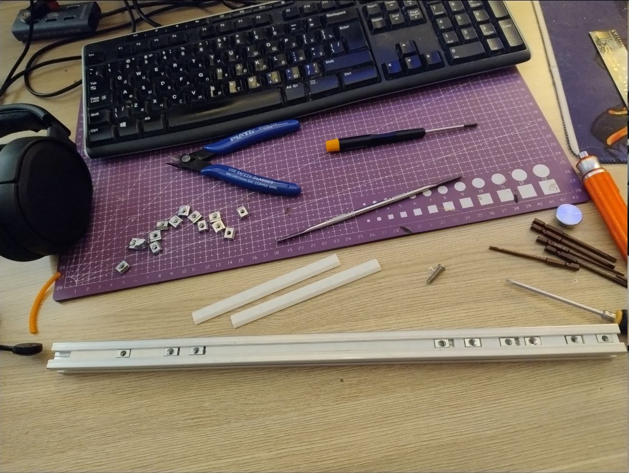
 Sadly, it does not solve all assembly problems - I did have to loosen everything, mount back panels and sorta squish the frame until it is properly squared, before tightening everything.
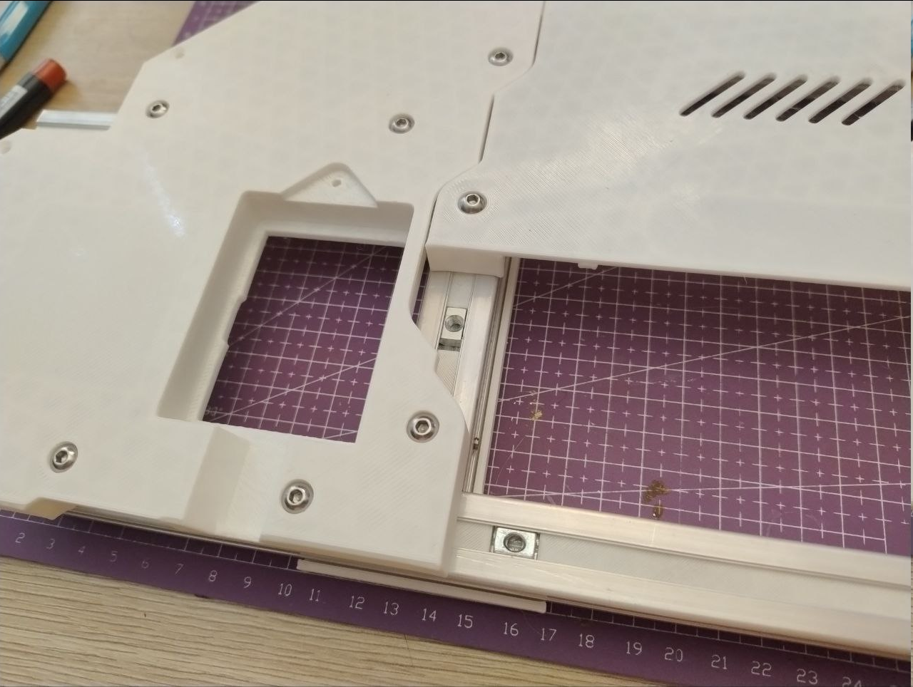
 Bonus content: this is how it may look in a HMD-centered setup (no HMD yet), when top monitor is removed - there are plenty of stuff to connect HMD in question both to signal (HDMI and analog) and power.
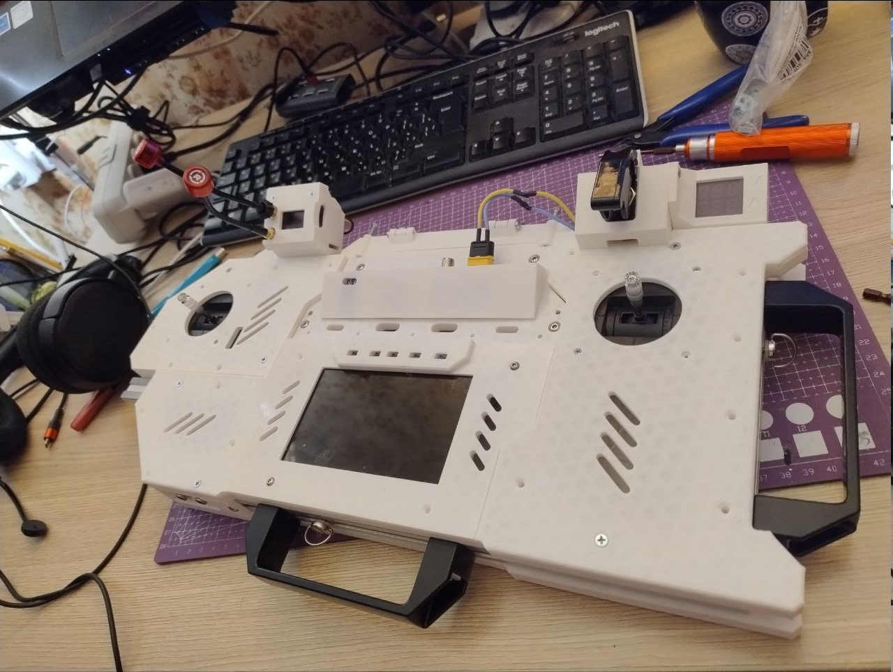
 And link to tutorial:
 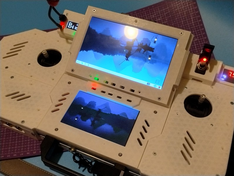 Some new stuff immediately shows up, so, here it comes in no particular order.
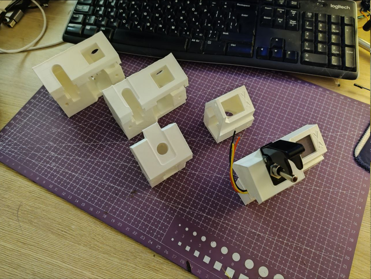 I had to iterate it at least a couple of times, first it was monolithic, then it was split in two halves to ease printing and simplify the design itself, and then it turned out that these round fuse holders aren't very ergonomic to install in cramped spaces, because their nut is not that easy to affix when tightening and they are very, very brittle if you wanna hold it with pliers
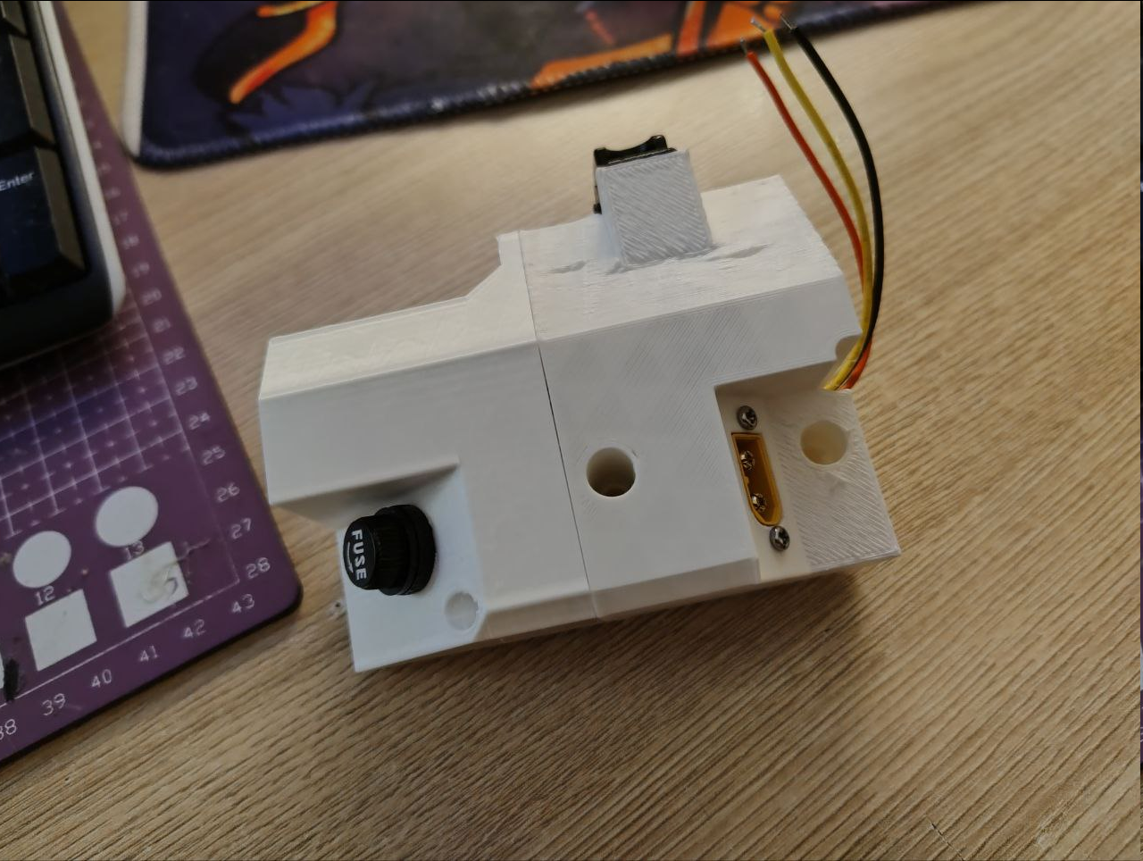 So I've went with this DC automotive fuse holder with a cap that mounts with two screws and called it a day:
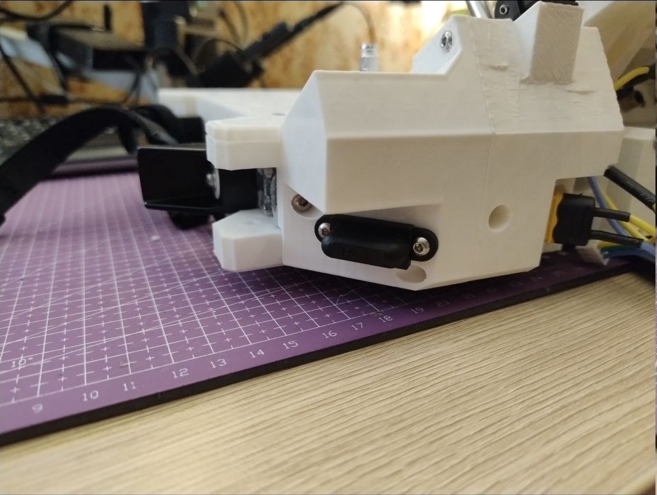
 I also had to wait for new meter to arrive because I wasted the first one when miswired it's current measuring connector.
 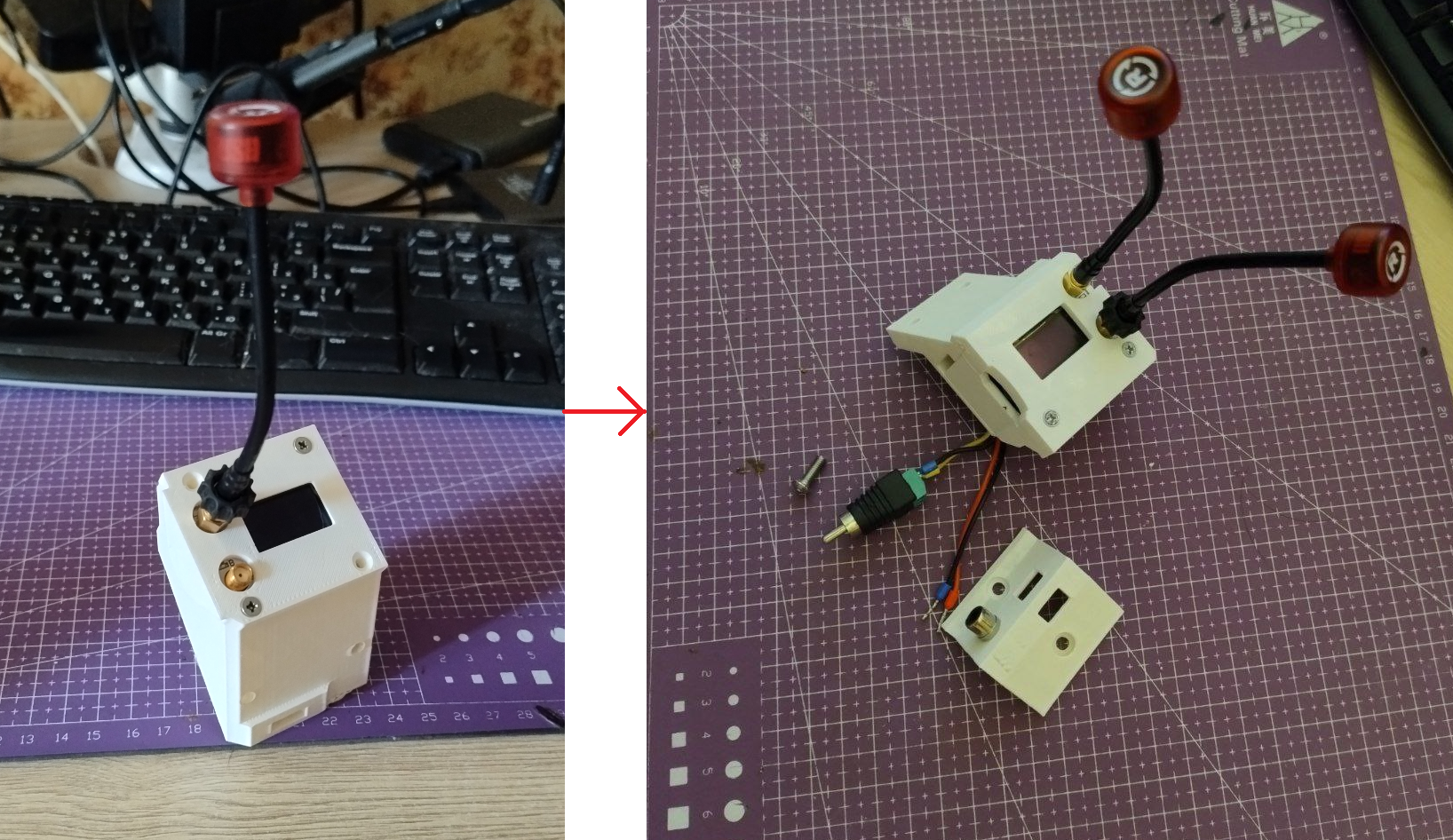 Initially it was almost monolithic, but then I've split it into a holder and signal/power connector group:
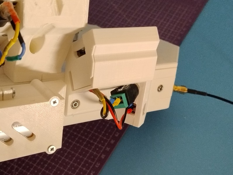
 And it's at this point I've realized how wasteful these redesigns are, because without proper forethought, minuscule changes make you dish out tons of material just to discard the next iteration (note how left and right assemblies have different rims - they were reprinted just for that small change)
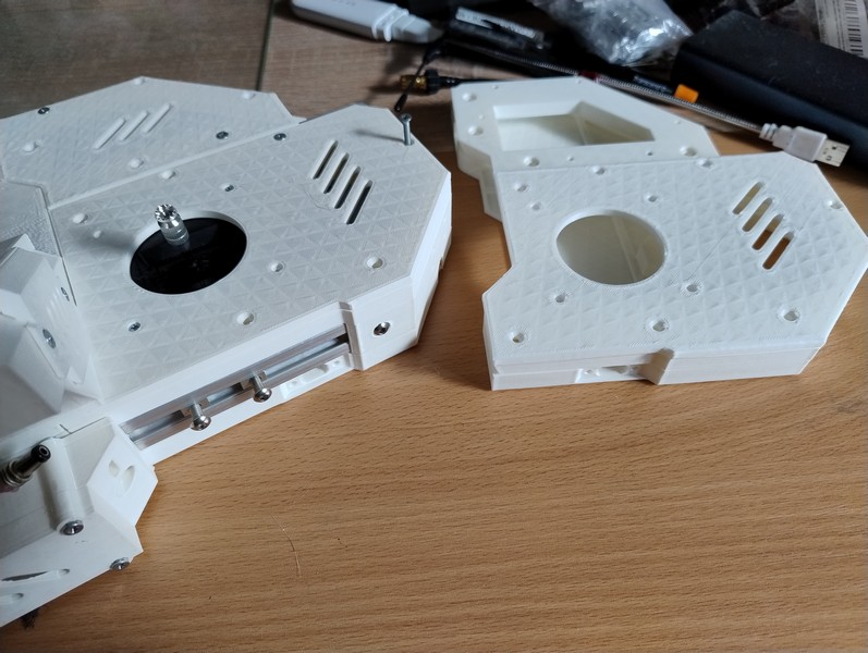
 Rail mounted 2S Li-Ion 26650 battery pack
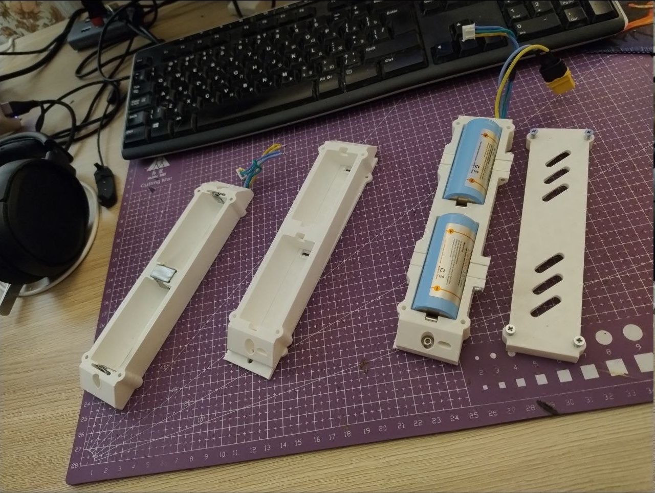 When most of the things connected, the backside looks much more busy than what it does, but I will probably come up with some kind of compact wiring solution to this, hopefully without compromises on functionality.
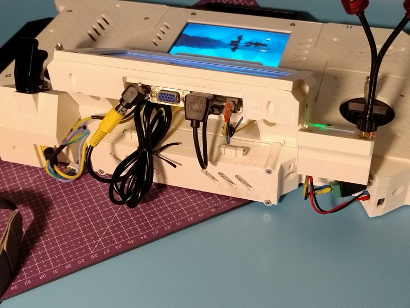 But that should be it for now! It moves and can't be more happy.