zakqwy
-
Aiming Towards Focus-Stacking Microscopy
05/10/2025 at 20:39 • 1 commentThe microscope I bought last fall to better see Circuit Graver work is pretty amazing. And also not amazing, perhaps; at this point, USB microscopes like this have been around for some time, and I'm just a bit late to the game. To recap, I have a USB-C version labeled for 50x - 1000x from a company called TAKMLY, and it cost around $40 at the time.
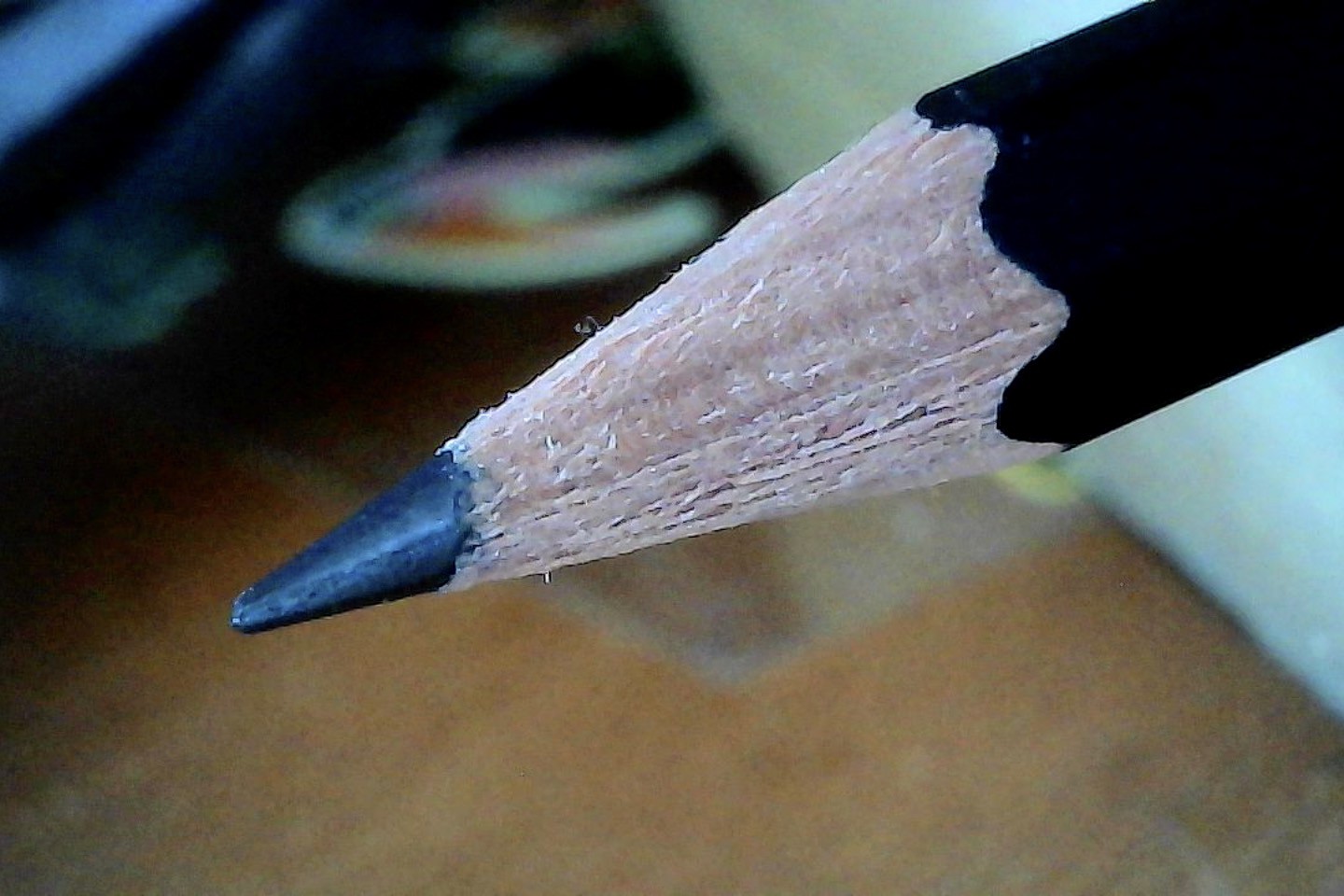
The microscope enumerates as a webcam and takes reasonable-looking 1920 x 1080 pictures. With decent but not excessive illumination the noise levels are pretty good, and the LED dimmer is a simple way to adjust exposure to prevent washout. It seems they achieve this on the cheap by opening the aperture pretty wide, so the main issue, particularly at high magnifications, is a short depth of field. Of course, this condition exists with commercial microscopes costing far more; it's just one of those tradeoffs you make when seeking out a high-quality image. Here is a shot I took at lower magnification of a recently sharpened pencil:
![]()
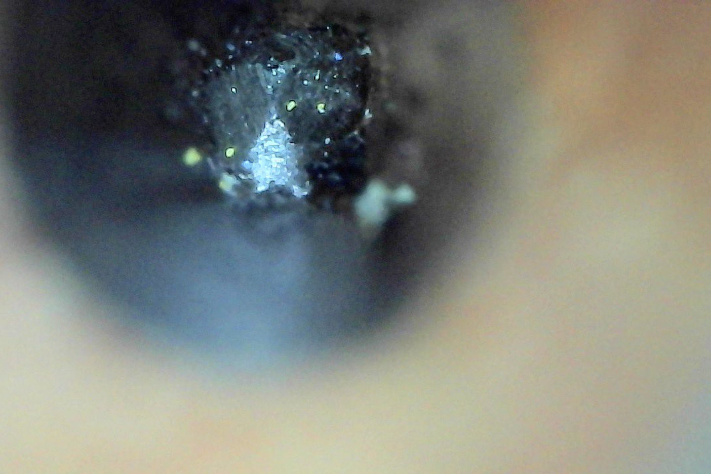
... and then zoomed in, showing little green bits of pollen which has suddenly appeared on every surface in my apartment:
![]()
... and zoomed in even more and viewed head-on; this picture took a long time to set up and isn't great, but the magnification is impressive. Note the shallow depth of field; only a fraction of a millimeter is in focus:
![]()
Held flat against my recently-dusted and pollen-encrusted electric piano shows a notably better image, since the focal plane matches the plastic surface and I was able to carefully adjust illumination while keeping everything still. Look how porous the plastic is up close! No scale here; might be time to finally buy a cheap calibration slide. I bet the green pollen bits are in the range of 10-25 microns:
![]()
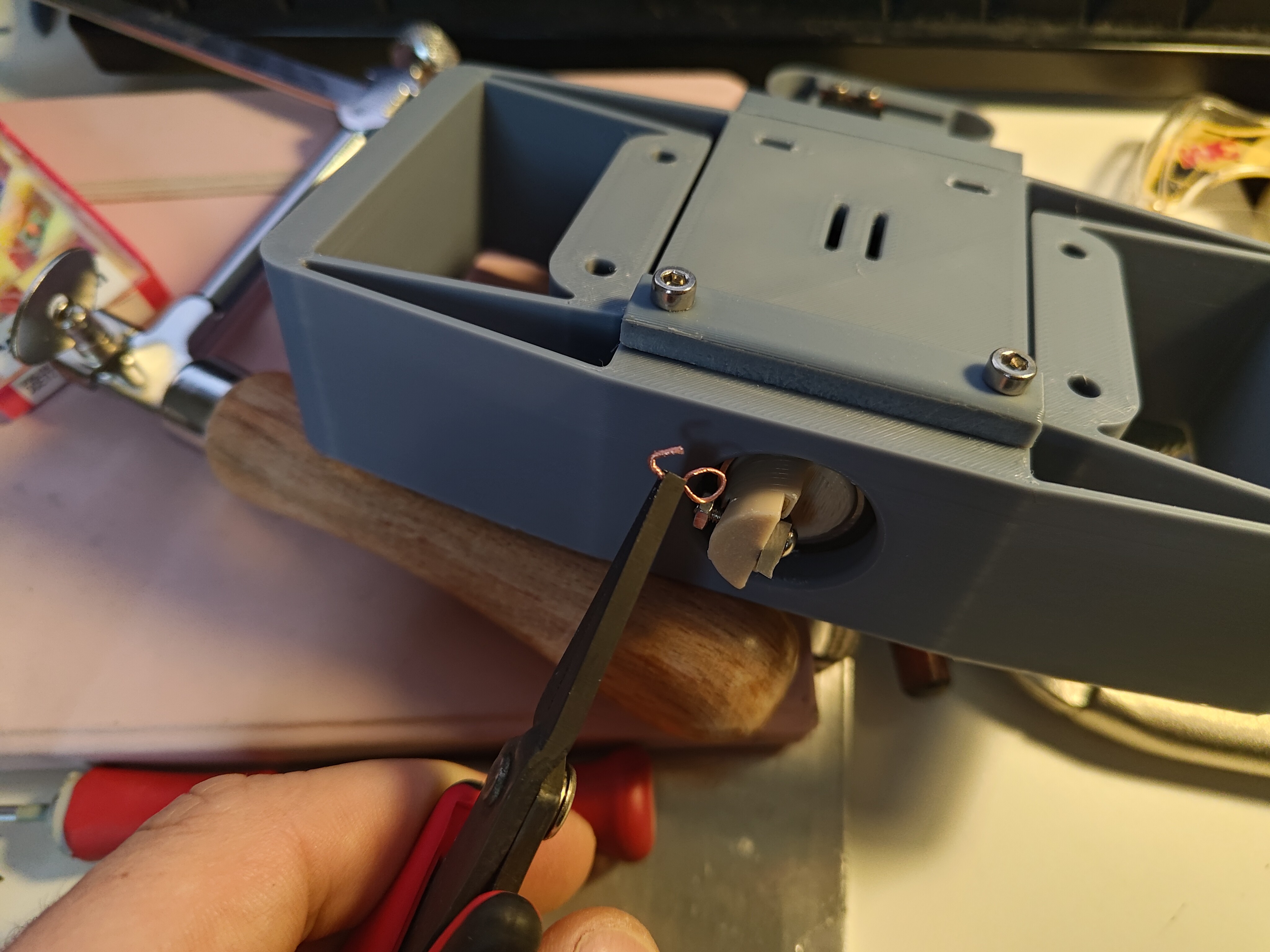
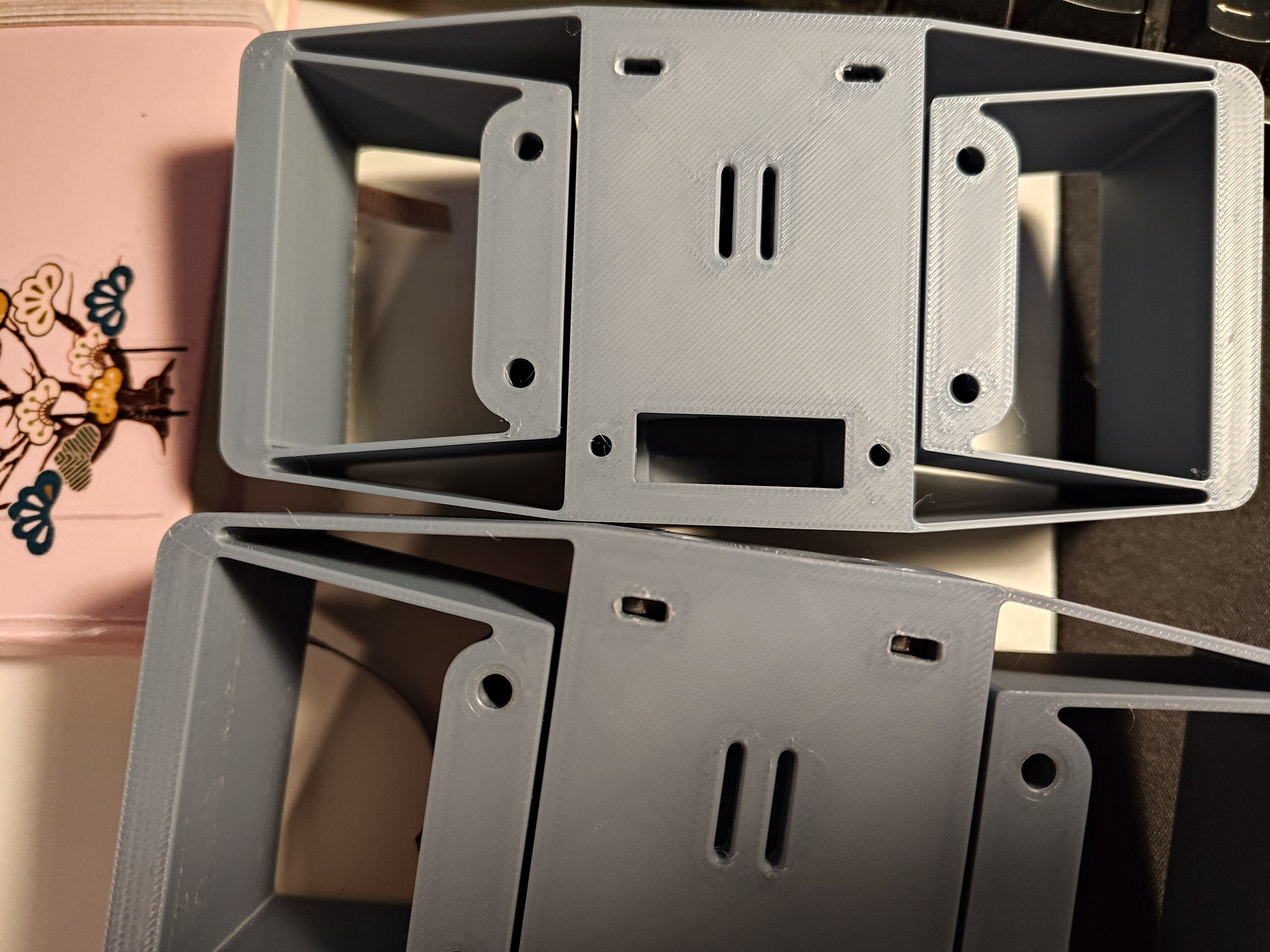
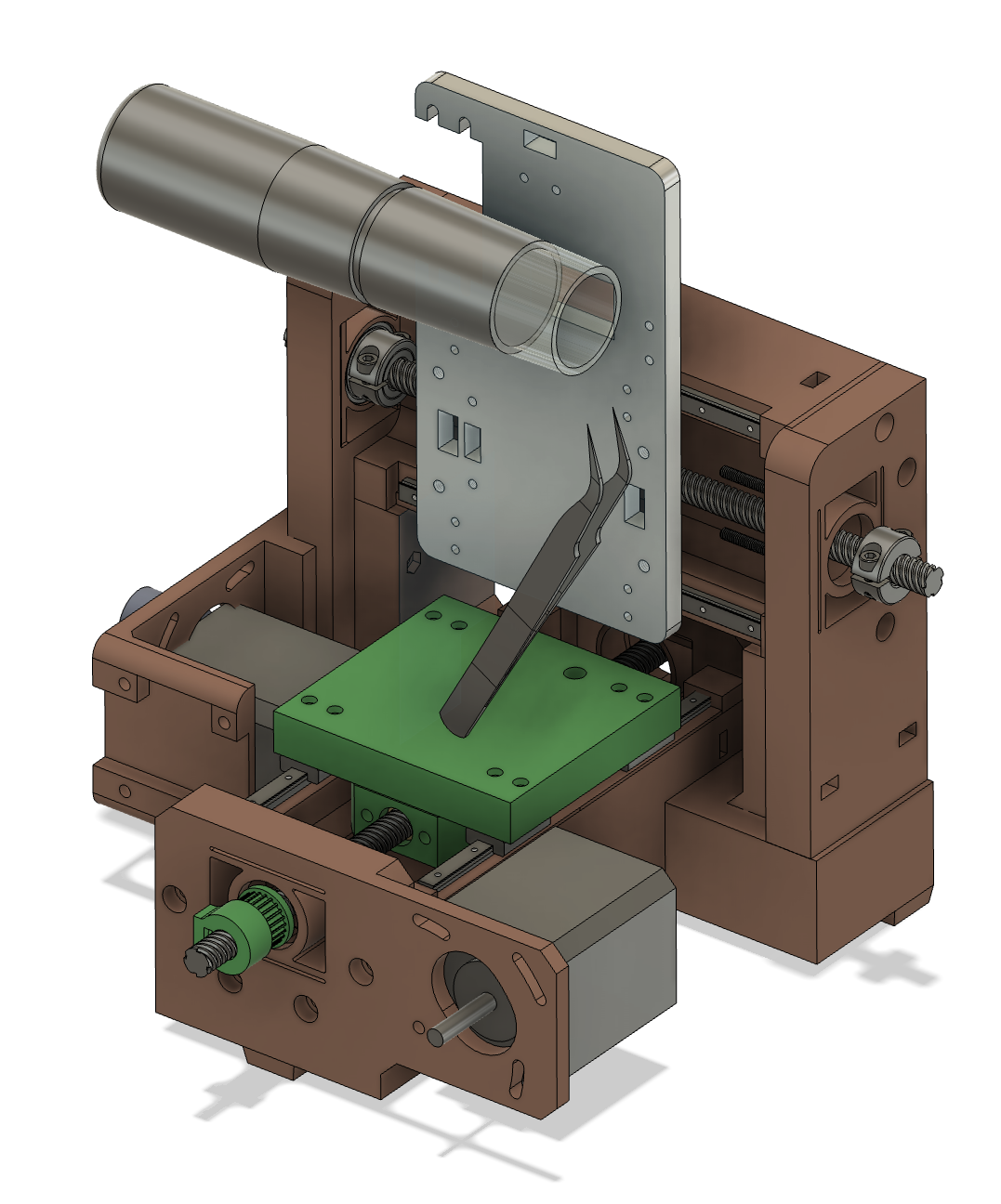
Due to the shallow depth of field and high magnification, just holding the sample and microscope stable relative to each other is tough. The included table stand has some adjustment but lacks the weight to really keep the microscope stable, and the clip that secures the stand to the barrel tends to slip off a bit too easily. So just having a multi-axis stage that lets me adjust the microscope and be assured it will stay where I leave it is a great improvement. Seems like a nice excuse to make a new platten for this machine:
![]()
I want to use one of the two "good" axes for precise focusing, so I oriented the microscope parallel to the X axis. Note the workholding plan; I'm going to devise a clever clamp for my tweezers that lets me pick up a sample and quickly secure it to the machine, probably with some kind of flexure and securing knob. Left-right (to the camera view) sample orientation is adjusted with the Y axis, while a bit of vertical movement is allowed by pivoting the tweezers at their base. Perhaps future work could hijack the R-axis to actuate the camera's zoom ring, but for now, just operating it manually will dramatically improve image quality.
And of course, once the system is working I can automate the X-axis and take a series of shots at precise focus intervals, and then use some kind of focus stacking software to mash them together. That's not something I've done before, so maybe it's less trivial than I assume. One thing at a time.
-
The PCBs of Supercon 8
04/13/2025 at 14:43 • 0 comments... and suddenly, it's 5 months later! A fresh Circuit Graver article was posted a few days ago along with a video of my talk, so it is time to post a long-overdue update while the machine is on my mind. Since I wasn't scheduled to speak until Sunday and wanted to carve a few boards with community members, I first set the machine up at Supplyframe HQ during the Friday night party to attract a bit of interest. Success!! When I subsequently scouted a spot in the alley next to LACM on Saturday, I found plenty of PCB designers in need of fabrication.
![]()
above, delightful soldering tent chaos in the alley next to LACM; below, the Circuit Graver set up and running jobs for friends old and new.
![]()
Of course, I neglected to take photos of any of the PCBs I carved during the event, let alone ask permission of the designers to share them. Thankfully everyone sent over *.svg files via email, and several responded with photos and share-approvals when asked a few weeks later. I'm still waiting on a few folks I pinged again, so hopefully this list will grow a bit in the near future!
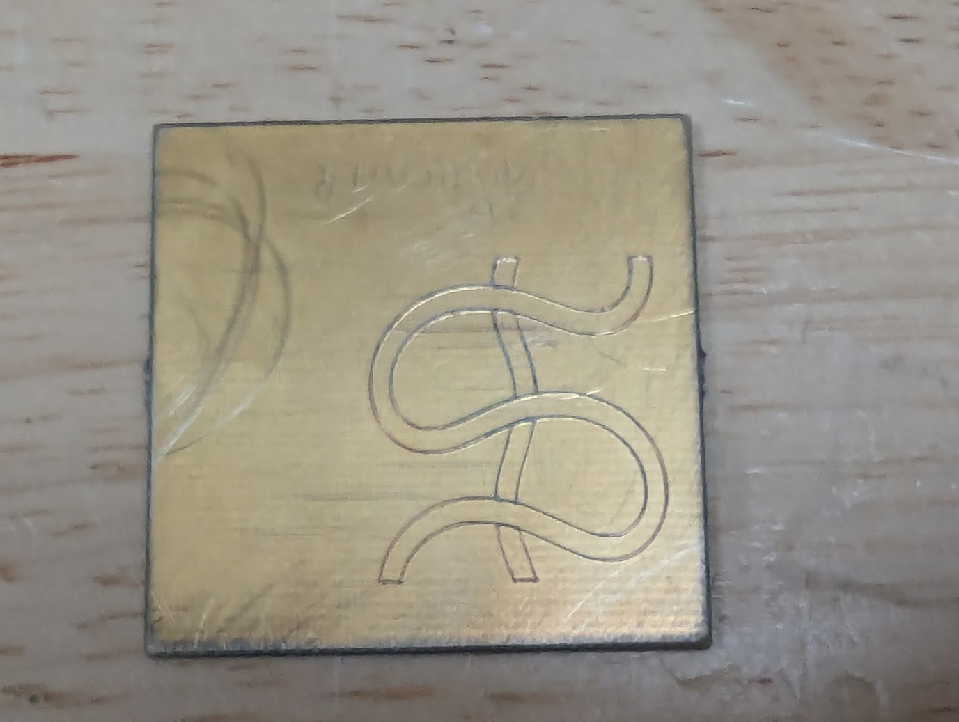
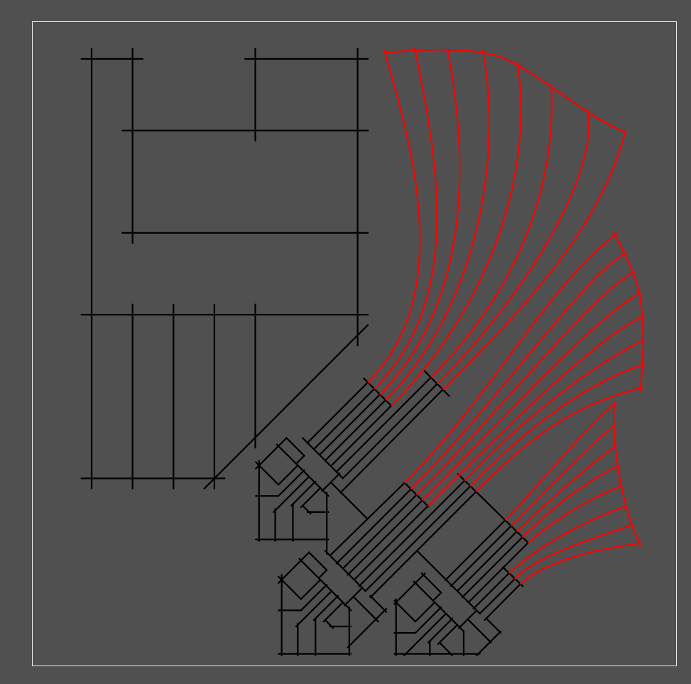
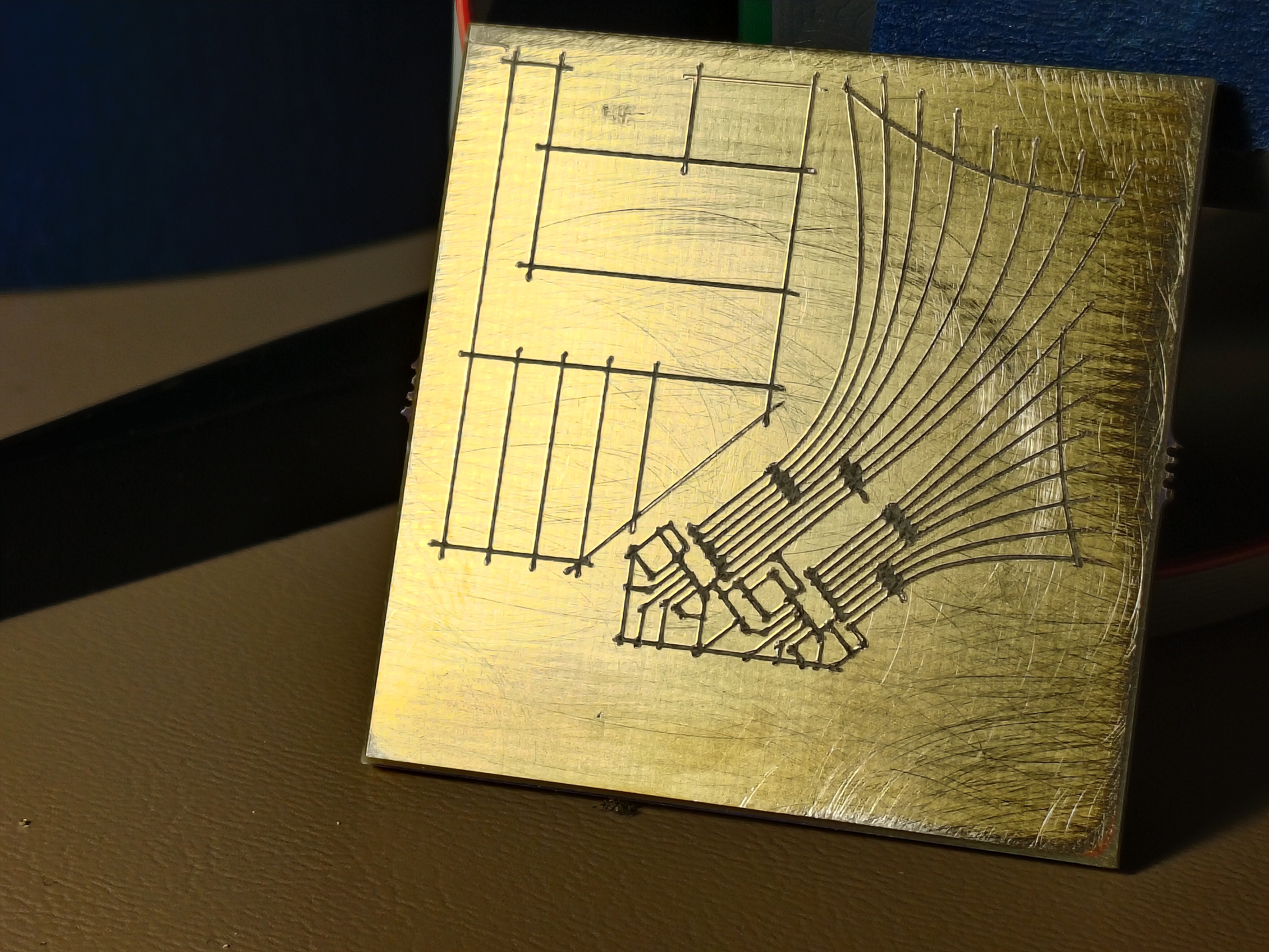
@John Thurmond had an interesting design generated using Zoltan Sylvester's meanderpy, a Python module which, well, meanders. It seems to be a great starting point for the kinds of fabulous plotter art that Zoltan sells on Etsy. The file John provided is a pretty simple river-looking thing, and it came out quite nicely in gold-plated FR4:
![]()
I sat next to Squidgeefish on Saturday, who was kind enough to make a bit of space for the machine and subsequently had a great PCB ready for the Circuit Graver -- a boost converter add-on for their SAO project. It's a fabulous project, and they pulled together a great write-up of the add-on and boost converter after the conference, including lots of details about the board we made together. Here is an image from that post, after soldering and bring-up; be sure to click through to see others:
![]()
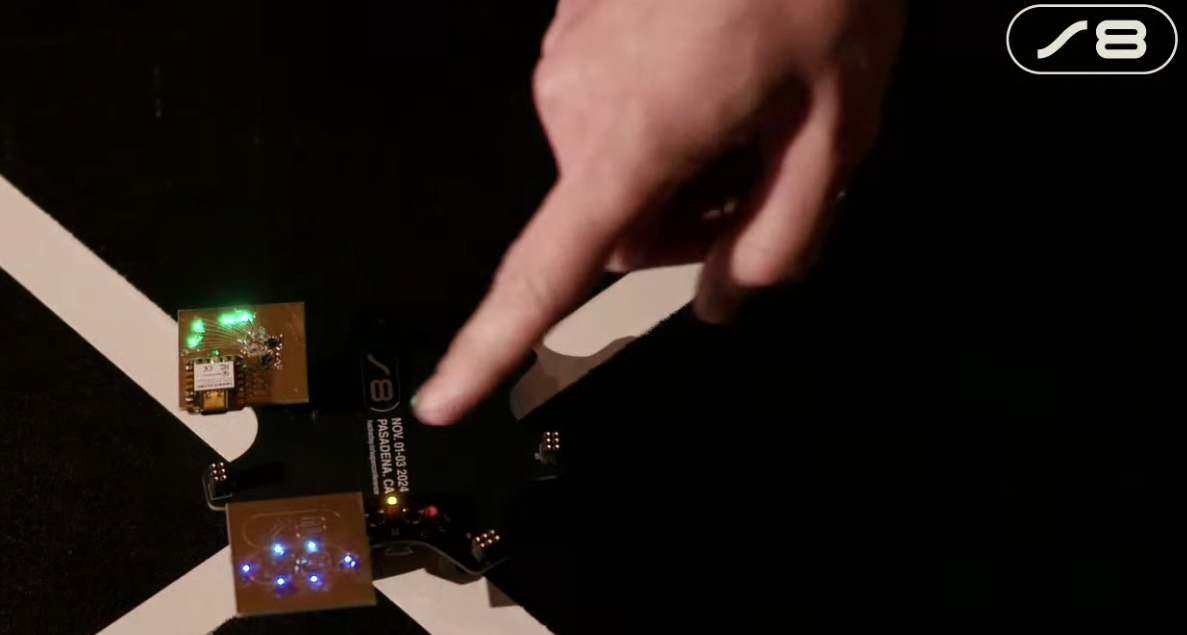
I thought it would be neat to make a custom PCB for the badge hacking contest, so I carved a Supercon 8 "S8" logo into a bit of FR4 and lit it up with six blue LEDs from my parts bin. I like that they're from the same reel of parts I used on my badge hack during the first Supercon a decade earlier! Screenshot shamelessly stolen from Hackaday's live feed of the badge ceremony:
![]()
Allie Katz has a sweet logo which seemed conducive to carved linework, so we decided to PCB-ify it! The workflow for this one was great, I used Inkscape's bitmap tracing tools on the graphic lifted from their website. It looks so excellent rendered in gold-plated copper:
![]()
-
an article is live. and another data point appears in the comments!
11/07/2024 at 14:48 • 0 commentsDave Rowntree and I chatted a bit at Supercon and he ended up writing a nice article for Hackaday on the machine. Thanks Dave!
https://hackaday.com/2024/11/06/rapid-prototyping-pcbs-with-the-circuit-graver/
One of the great things about seeing your project get a bit of press is that it can get enough coverage that interesting people with relevant experience chime in. That seems to have happened here! A commenter named Shara linked to a few pictures which used a used drag knife to carve up a bit of copper-clad substrate, and it looks like they got great results:
Copying the photos here in case the imgur link dies; as suggested above, these aren't my photos:
![]()
![]()
![]() Shara! Whoever you are, please send a link to your project so I can include it here. These tests look like thin FR1; it seems you might have had the same challenges I had with entry/exit points shorting, but got it to work in the end with hand touch-ups or maybe toolpathing improvements. I'd love to learn more about your setup and see a video of it in action! What feature size can you hit? How fast? Does the cutter get dull quickly? What kind of machine is it driven by?
Shara! Whoever you are, please send a link to your project so I can include it here. These tests look like thin FR1; it seems you might have had the same challenges I had with entry/exit points shorting, but got it to work in the end with hand touch-ups or maybe toolpathing improvements. I'd love to learn more about your setup and see a video of it in action! What feature size can you hit? How fast? Does the cutter get dull quickly? What kind of machine is it driven by? -
in pasadena!
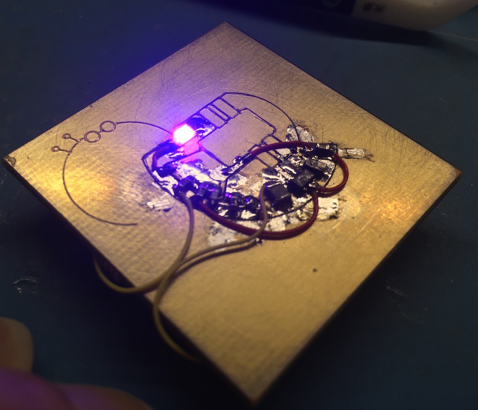
11/02/2024 at 13:12 • 0 commentsI finished the SAO at the eleventh hour, the day before getting on a plane. It works! Well, one LED has some challenges, but we're counting this as a win. It's also a great example of why vias are important; driving two shift registers means they share a lot of pins and need a lot of tedious (but delightful, of course) magnet wire work.
![]()
At some point I'll post more pictures, maybe installed on the badge. But for now:
![]()
The machine made it to LAX without much trouble, and I managed to spot it getting unloaded from my (well, Delta's) 757-200:
![]()
I got to Supplyframe HQ around 4 PM and set up on a table with friends, and spent a few hours showing folks how the machine works and making sample boards. And soliciting designs from conference attendees! I brought ~30ish blanks and it would be great to go home with none.
-
soldered the fussy(est) bits!
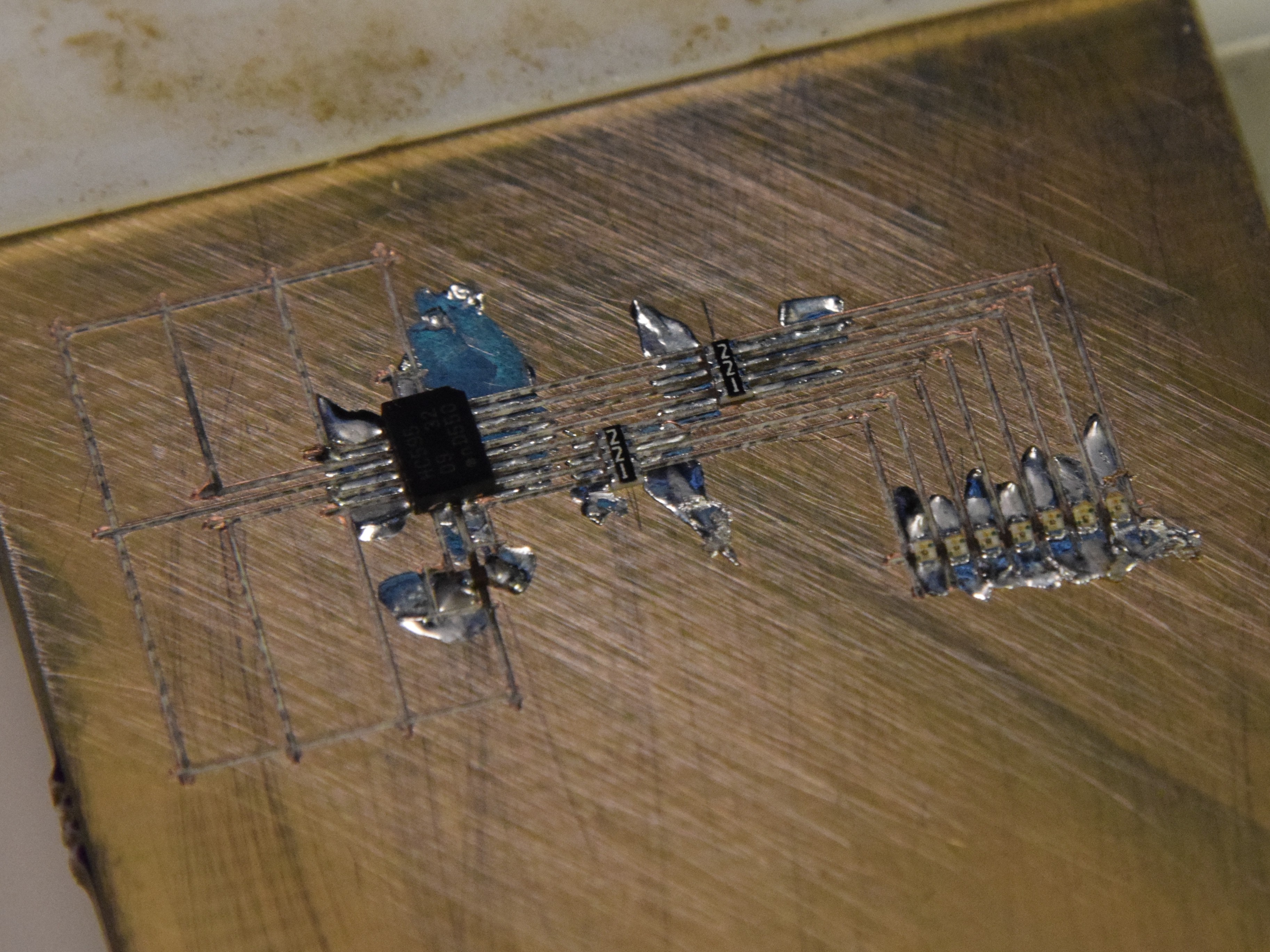
10/31/2024 at 12:12 • 0 commentsI got up early and soldered the DFN HC595s and 0804 resistor packs before heading to work:
![]()
I used braid to clear a few obvious bridges and checked resistance pad-to-pad across the resistor networks. They were a bit fussy to solder because of the aforementioned circuit carving gore; I had to reflow a few of the pads and one of them ended up needing a tiny length of bodge wire to bridge a gap in the copper. But after not too much work each trace beeps out as it should and I didn't detect any bridges between adjacent nets! The other stuff (LEDs, a few bypass caps, the ESP32, and the SAO header on the back) is pretty low-risk, so I don't anticipate any issues with getting this woken up this evening with a few hours to spare. Huzzah, etc
-
curvy leds + fab
10/30/2024 at 22:00 • 0 commentsI used Inkscape to make the LEDs a bit more interesting:
![]()
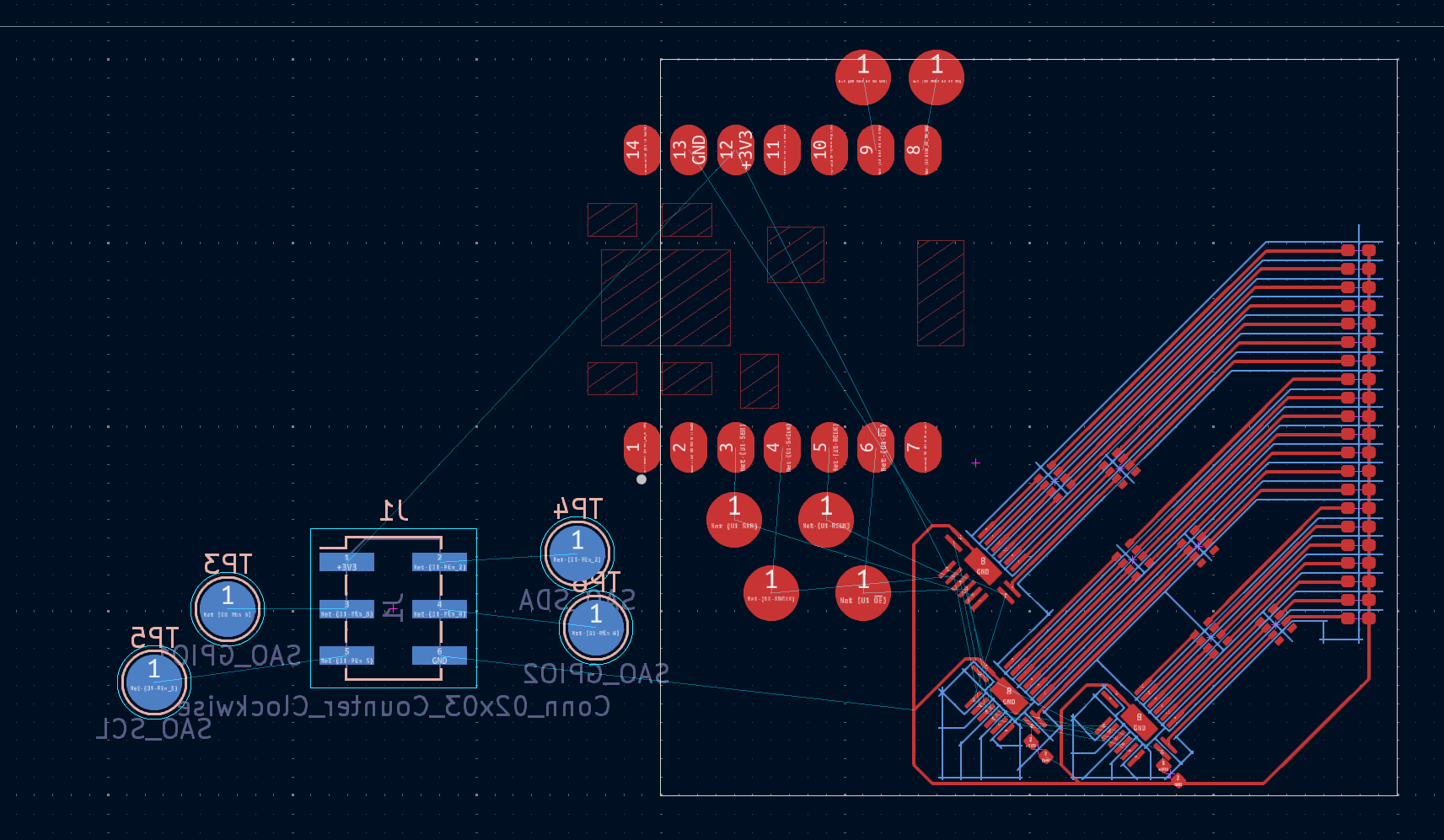
After a quick air-cutting fab test, I de-escalated the LED count to save Y-axis travel:
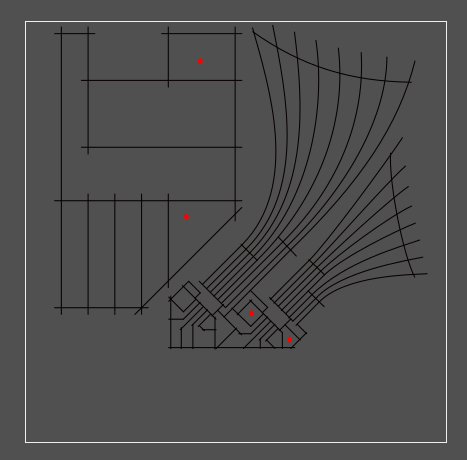
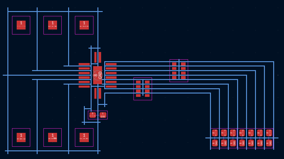
[yup, screenshots of inkscape]
The red dots are shorts to ground or adjacent pads after fab. Not bad! The first round was weird, though; I kept the lower LED cluster grouped and saved as an Inkscape SVG (as opposed to "plain"), and the grouped bits didn't rotate properly:![]()
Mmm such fascinating gremlins. I un-grouped and re-saved and ended up with a good board which beeped out after fixing the aforementioned shorts (fewer than last time!):
![]() Oof, the resistor packs are particularly gruesome. 4-way crosses aren't great. Some toolpathing cleverness for narrow trace areas is really going to be necessary at some point; crossing trenches can pull pretty severe chunks out around narrow feature areas. I think this is solvable but will take a bit of experimentation.
Oof, the resistor packs are particularly gruesome. 4-way crosses aren't great. Some toolpathing cleverness for narrow trace areas is really going to be necessary at some point; crossing trenches can pull pretty severe chunks out around narrow feature areas. I think this is solvable but will take a bit of experimentation. Now for the header pads on the reverse side! Since the badge design is released, I was able to adjust the angle so in the upper left plug the square would sit upright (roughly 33 degrees):
Fab was perfect, beeped out on the first try! I wasn't shy with the pressure wheel since this is such a simple design, but it was nice to have one require no work either way. I might be able to back off the overcut a bit, in fact:
![]()
-
slides and a sao sprint
10/29/2024 at 02:56 • 0 commentsSlides are turned in! Sent yesterday evening, a day ahead of the double-extended deadline. Tonight, I decided to make a badge add-on, now that we know the conference badge is a carrier. Nothing crazy! An extension of the first test circuit, again using tiny but easy to use parts I have on hand: three shift registers, 21 LEDs (since the 8th digit is hard to route without vias), six resistor packs, the same ESP32C3 XIAO board, and a 6-pin add-on header on the back. I have enough blue, green, and yellow 0402 LEDs, and will likely go green this time. Would be great to have orange, but time is short.
-
the circuit works!!
10/23/2024 at 03:50 • 0 commentsReckless! I re-fixtured my lovely circuit (the only complete circuit I've made so far) and carved in another set of pads to suit an ESP32C3 XIAO module from Seeed Studio. I flashed a fresh Micropython bootloader and wrote a few lines to fill the shift register with 1s and 0s with 0.5 s delays.
It works!
For now, sleep; but to come, more images, some notes on the design workflow, a video of fabrication (carving on the same board as a bunch of soldered parts, ack!), a bit of code, a discussion on the various repairs and bodges it took to get here, a love letter to 34 AWG polyurethane-insulated magnet wire, etc.
-
a circuit!
10/22/2024 at 01:59 • 0 commentsOof, behind on updates; I spent a great Saturday back at the CBA where Jake helped me wake up the rotary axis. We carved a lot of bad circuits and a few good ones; after a few manual touch-ups, one beeped out so I soldered on the appropriate components:
![]()
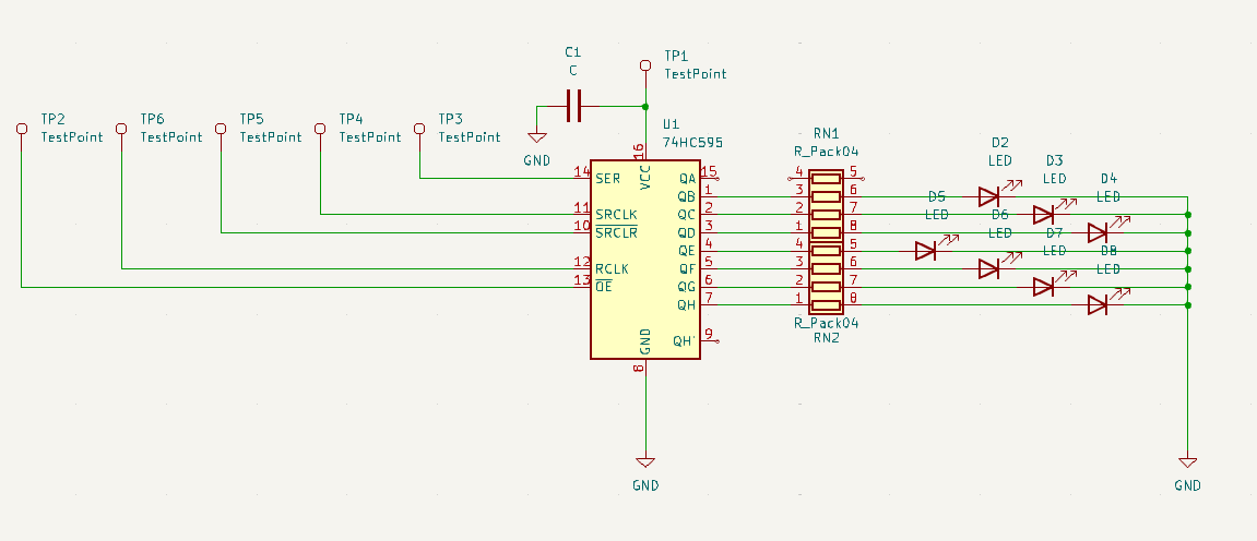
It's not a complicated circuit, just an HC595, a pair of 220-ohm resistor packs, and a handful of yellow 0402 LEDs:
Not yet tested, but no shorts! Tomorrow(ish), I'll drop some wires on the six driver pads and see if I can make some blinkies happen with an external driver IC of some kind.
And more to come! Lots to show: pictures and videos and failures and heatsinks and limit switches and the rest. Slides are now due in a week, but I'd rather not push that, so I may prioritize the talk over updates here for the time being.
-
time for some circuit carving!
10/13/2024 at 20:34 • 0 commentsOkay, a good bit to catch up on here! First, some early results, featuring a 0.5 mm pitch DFN-packaged 74HC595 left over from #blinktronicator builds oh so long ago:
![]()
X/Y/Z axes are working! Everything is working, with a big caveat that I'm not quite getting the result quality I'd like. Of course, I'd really like 150 micron (6 mil) spaces and traces, but that seems to be right about the limit of the technique. I picked up a cheap USB microscope and got some images of carved trenches with 0.3 mm stepover:
![]()
![]()
Many interesting things to note from test 16! First, specs: 20 passes, 0.3 mm spacing, 10 mm long strokes, a thinner 1.2 mm Z-axis flexure, and 1.5 turns of the pressure knob after touching off the material. I started doing this by checking continuity between the cutting tool and the PCB which works well, but is a bit awkward; a loop of wire attached to the tool helps a lot, as it provides a place for one multimeter lead to rest:
![]()
Second, the entrances and exits are dramatically different; you can see how the cutter digs its way down to the right depth, leaving a bit of unusable area at the front of the trace, then stops clean. Note that these photos are after a quick 320-grit deburr, so the curly chips are absent. Before sanding the cuts look something like this:
![]()
That was from a slightly lower pressure run, probably 1.0 or 1.25 turns past touching. Note how much the copper smears down the trench! In one case it completely bridges the gap, but even in the others it looks like there may be some hairs crossing from one side to the other. I think that means, at least for this setup (cutter, flexure, etc), 150 um trenches might be a reasonable minimum.
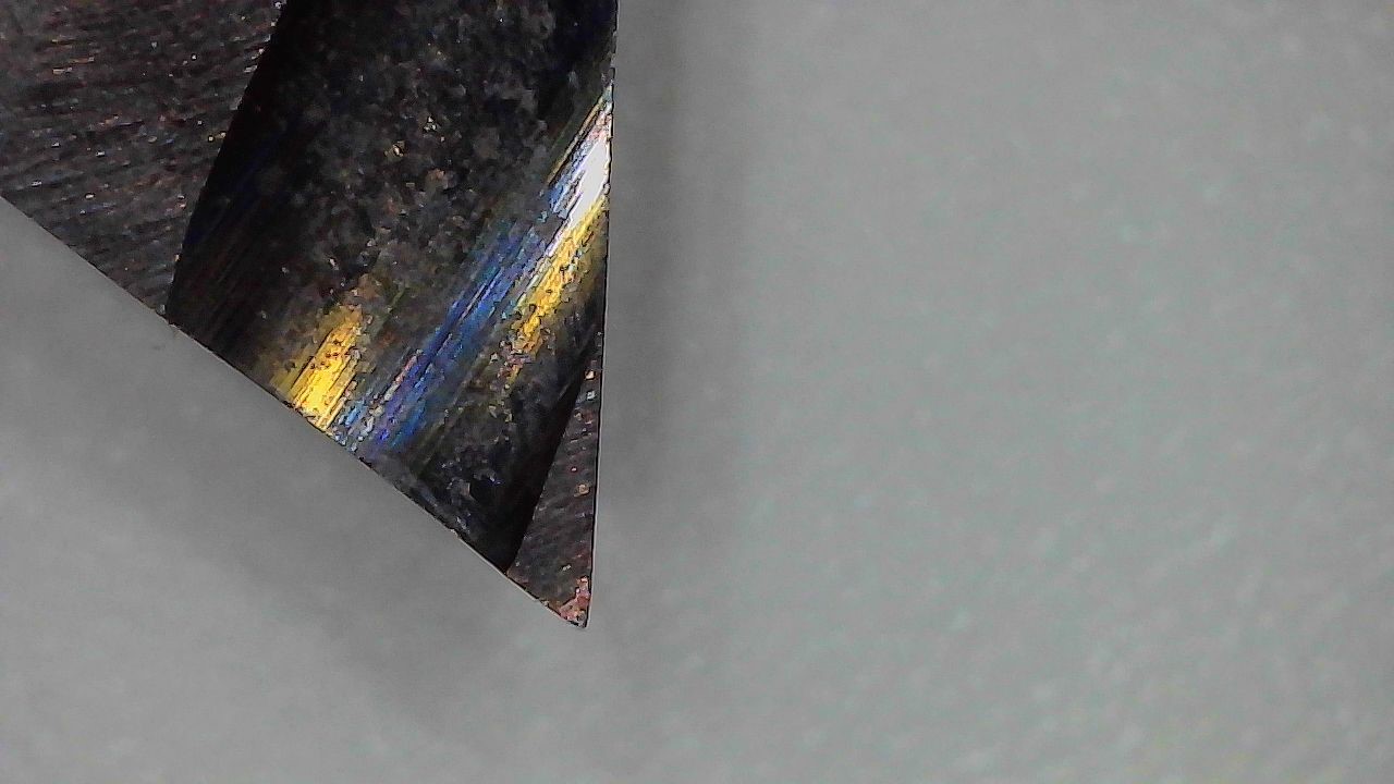
The tool looks okay under magnification, maybe a bit rounded at the very tip, but still pretty sharp:
![]()
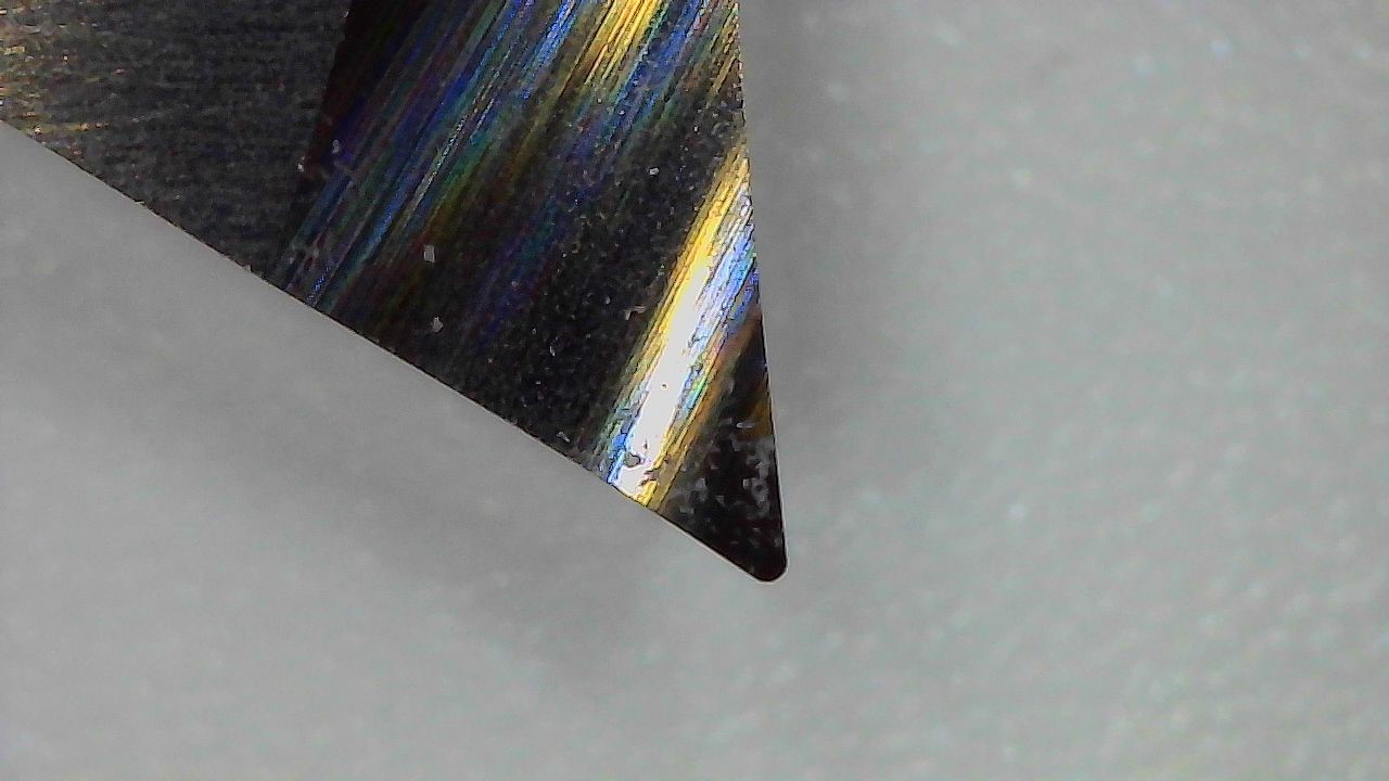
For comparison's sake, an unsharpened tool shows off its 0.1 mm tip radius:
![]()
Here is the old 1.6 mm Z-axis flexure next to the new 1.2 mm version:
![]()
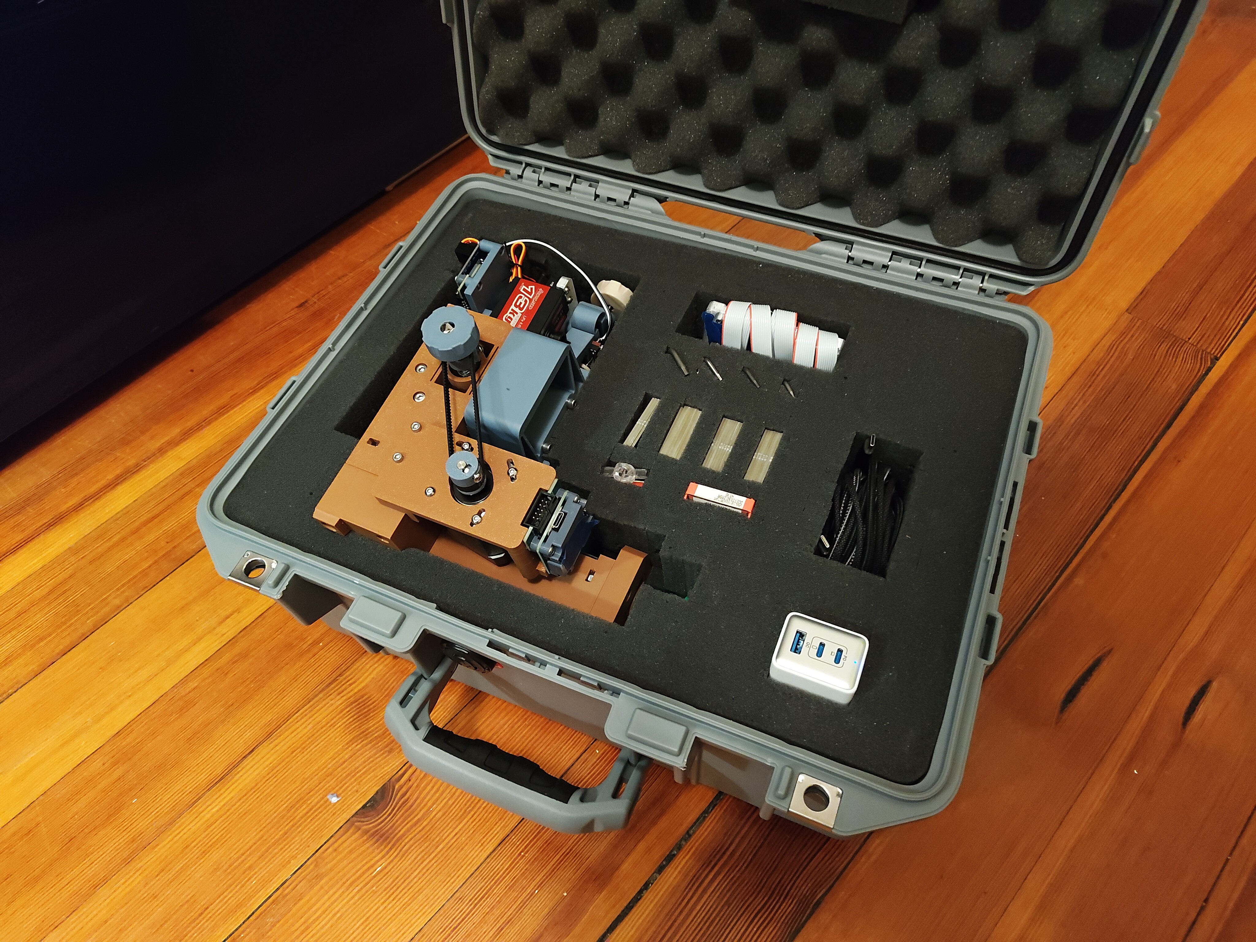
Other things too: fitting the travel case; generating test patterns using a Python library called drawsvg; Big Wheel Mode to gear down one axes by 4.25 times (since that fit my growing but still sparse belt collection); tests 1-15, some of which looked quite bad; lots of videos of the machine carving FR4; breaking and re-printing a number of parts; and a few new tools, like a diamond scribe and a not great jeweler's saw. But for now, a break.


 Shara! Whoever you are, please send a link to your project so I can include it here. These tests look like thin FR1; it seems you might have had the same challenges I had with entry/exit points shorting, but got it to work in the end with hand touch-ups or maybe toolpathing improvements. I'd love to learn more about your setup and see a video of it in action! What feature size can you hit? How fast? Does the cutter get dull quickly? What kind of machine is it driven by?
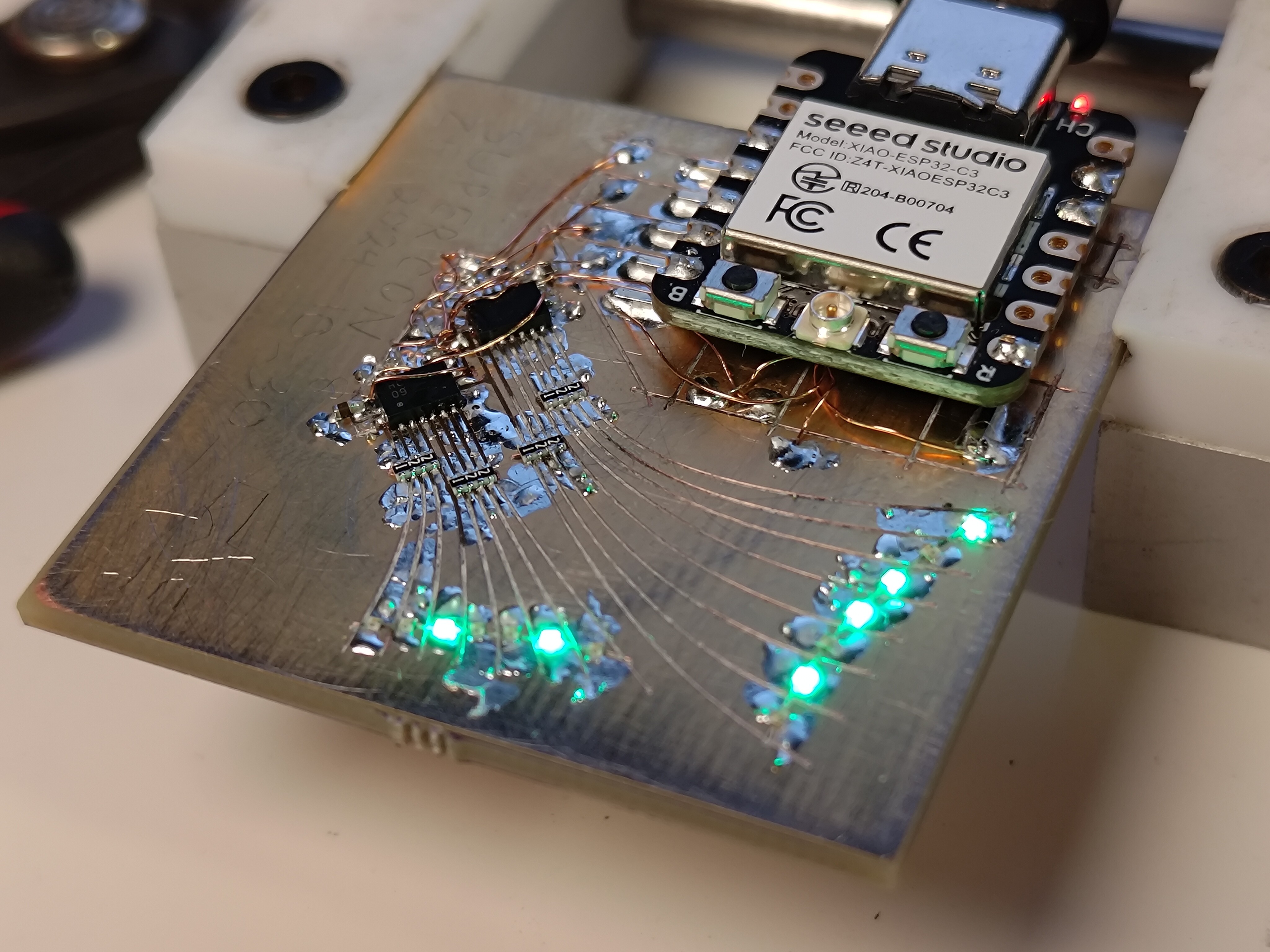


 [yup, screenshots of inkscape]
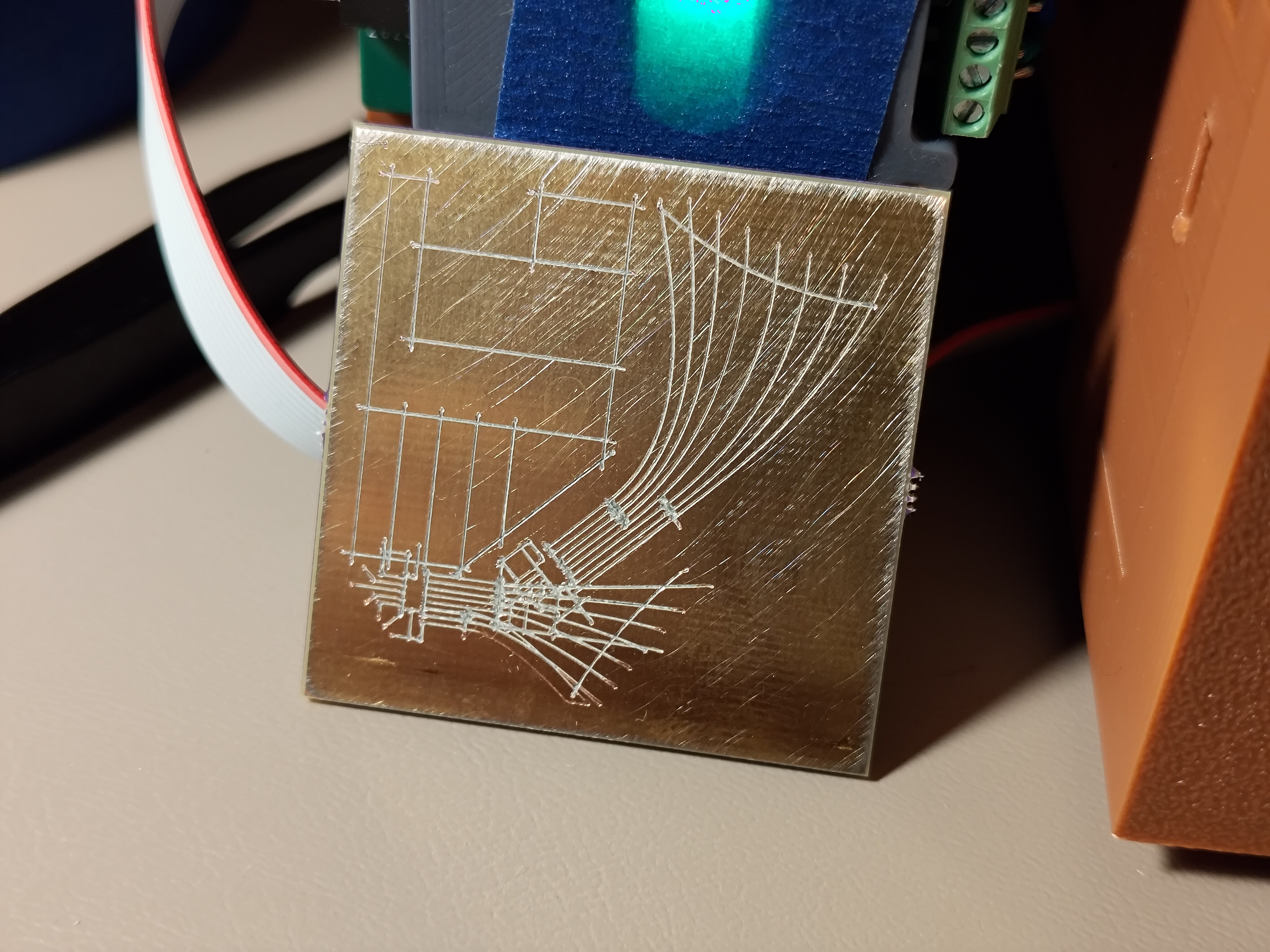
 Oof, the resistor packs are particularly gruesome. 4-way crosses aren't great. Some toolpathing cleverness for narrow trace areas is really going to be necessary at some point; crossing trenches can pull pretty severe chunks out around narrow feature areas. I think this is solvable but will take a bit of experimentation.
 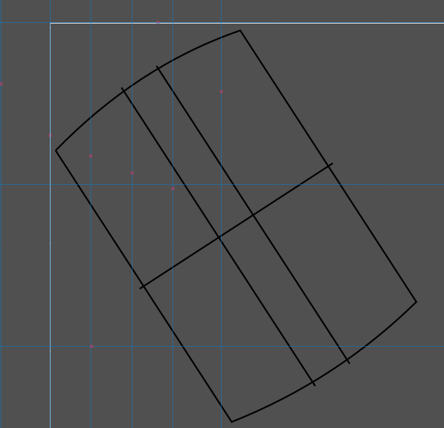 Fab was perfect, beeped out on the first try! I wasn't shy with the pressure wheel since this is such a simple design, but it was nice to have one require no work either way. I might be able to back off the overcut a bit, in fact:
 Not yet tested, but no shorts! Tomorrow(ish), I'll drop some wires on the six driver pads and see if I can make some blinkies happen with an external driver IC of some kind.