 MagicWolfi
-
Pico2 Rev2
7 days ago • 0 commentsJust received revision 2 of the board!
This time I went for real castellated holes on 3 sides, even though JLC charges an arm (pun intended) and a leg for it.
The 2nd big change is the switch to the RP2350, if you counted the pins. I was lucky to get into their samples program and have some RP2350A and B (including Flash and crystals) at my desk. Some soldering required.
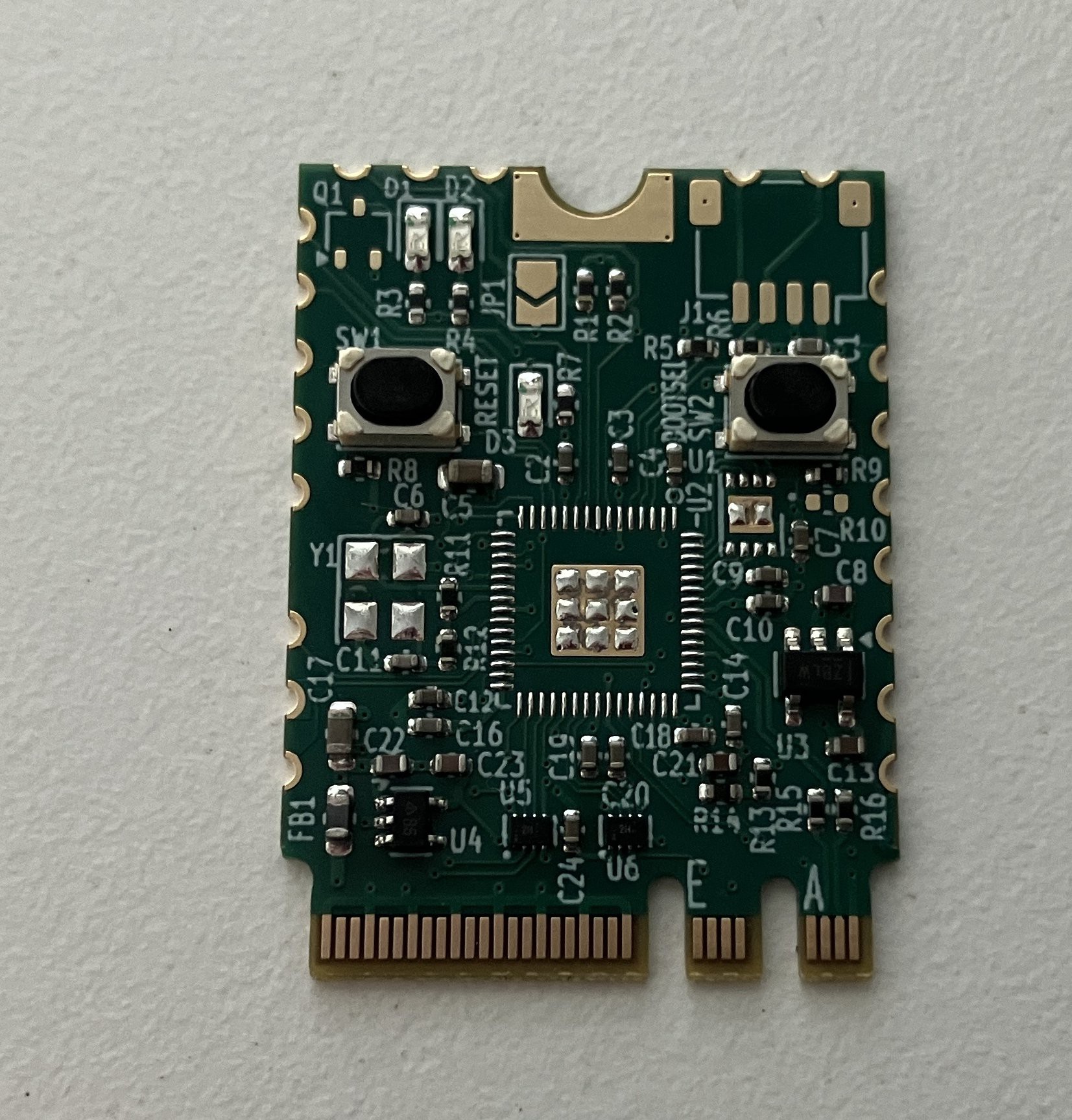
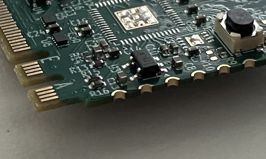
Here is a nice view of the board and the castellated holes detail. Test firmware is running on a Pico2 already.
![]()
![]()
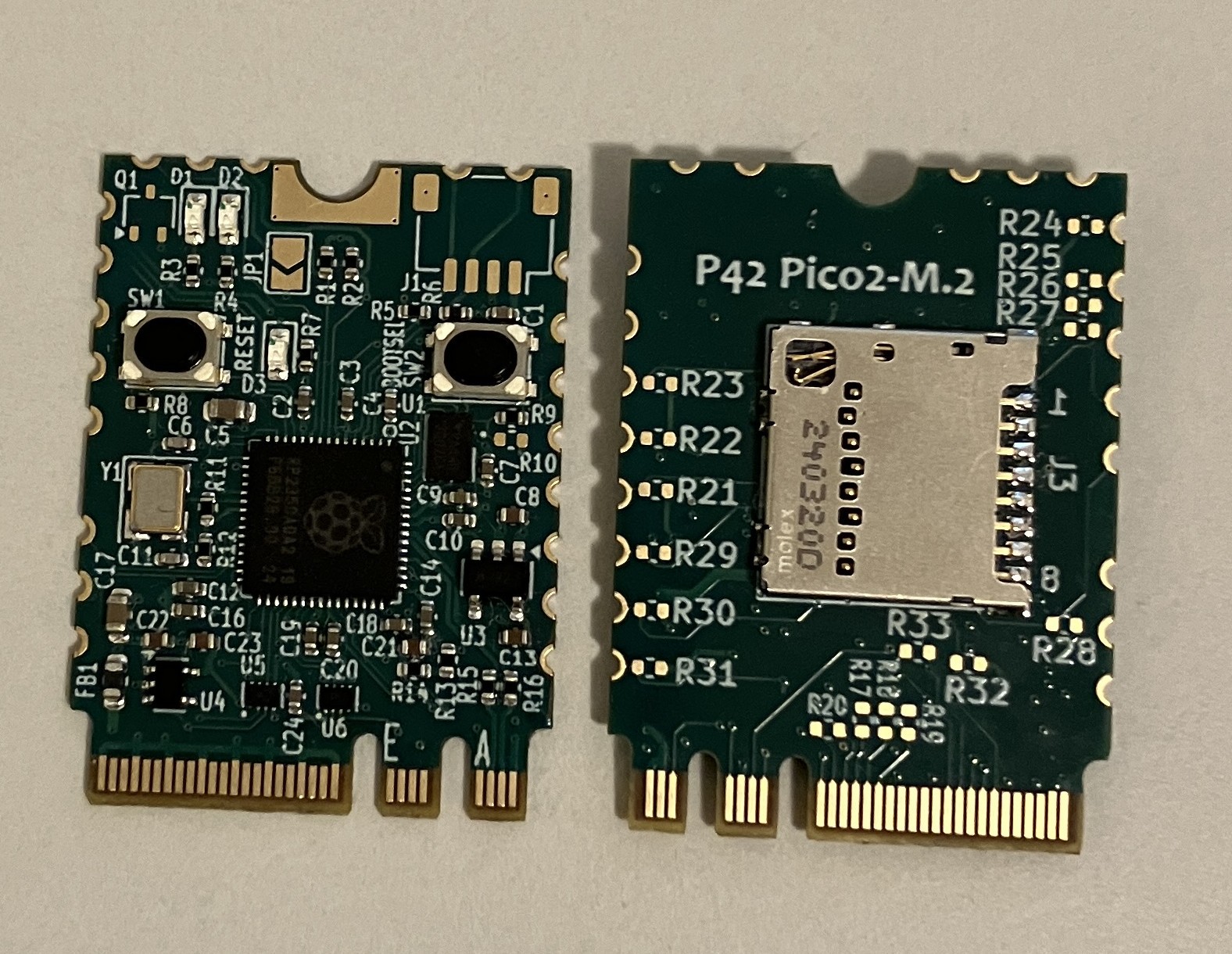
And some hot air soldering later, the board looks like this and is operational. SD card is alive, UART to the M.2 interface and all GPIOs. Still missing the QWIIC connector and a SC70 p-FET for the core voltage LED. Also the design decision to use an external LDO instead of the internal switcher for the 1.1 V core supply has proven to be good and will make the BOM cost being less.
![]()
-
SPI1 SD card success
01/25/2025 at 02:49 • 0 commentsDocumentation update
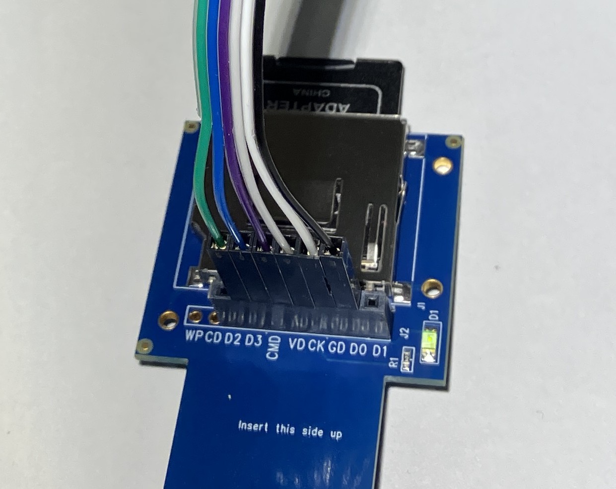
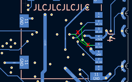
SPI1 is working with the following hardware setup:
#define GP Wire SD Adapter SD card pin SD_CS 13 green D3 2 SD_DI 12 black D0 7 SD_DO 11 blue CMD 3 SD_CLK 10 grey CK 5 This was more difficult than it should be, but finally it is done.

![]()
SDcard test.
Writing to test.txt...done.
test.txt:
1161011151161051101033249443250443251461310
SD Card Speed Test...
Writing to byte.txt...done.
Duration [millisec]: 8250
FileSize [bytes]: 1048576
Write Speed(8bit) [KByte/sec]: 128
Writing to 16bit.txt...done.
Duration [millisec]: 13657
FileSize [bytes]: 2097152
Write Speed(16bit) [KByte/sec]: 157
Writing to 32bit.txt...done.
Duration [millisec]: 23569
FileSize [bytes]: 4194304
Write Speed(32bit) [KByte/sec]: 178
done.
>d

SDcard root directory.
System Volume Information/
        IndexerVolumeGuid               76      CREATION: 2024-12-20 22:24:20   LAST WRITE: 2024-12-20 22:24:22
        WPSettings.dat          12      CREATION: 2024-12-20 22:24:40   LAST WRITE: 2024-12-20 22:24:42
test.txt                18      CREATION: 2098-01-01 00:00:12   LAST WRITE: 2098-01-01 00:00:42
byte.txt                1048576 CREATION: 2098-01-01 00:00:42   LAST WRITE: 2098-01-01 00:00:58
16bit.txt               2097152 CREATION: 2098-01-01 00:00:58   LAST WRITE: 2098-01-01 00:01:22
32bit.txt               4194304 CREATION: 2098-01-01 00:01:22   LAST WRITE: 2098-01-01 00:01:12
>uSD Card removed!
And here is the instruction to fix the traces before putting on the uSD holder to hide the mod:
-
SD Card success
01/13/2025 at 02:04 • 0 commentsFor whatever reason (which I will find out later) I could not make the SD card work on the SPI1 port of the RPi Pico with (CS=GPIO13, CLK=GPIO10, MOSI=GPIO11, MISO=GPIO12).
So I did some re-wiring and used the standard SPI port with the pin mapping as follows:
#define SD_CS         17
#define SD_DI         16
#define SD_DO         19
#define SD_CLK        18

// uSD card
SPI.setRX(SD_DI);
SPI.setCS(SD_CS);
SPI.setSCK(SD_CLK);
SPI.setTX(SD_DO );
This approach worked flawlessly and I could do all the file system commands provided by the SD.h library.
A simple speed test did show sufficient performance for basic data logging:
SD Card Speed Test...
Writing to byte.txt...done.
Duration [millisec]: 10377
FileSize [bytes]: 1048576
Write Speed(8bit) [KByte/sec]: 102
Writing to 16bit.txt...done.
Duration [millisec]: 15828
FileSize [bytes]: 2097152
Write Speed(16bit) [KByte/sec]: 136
Writing to 32bit.txt...done.
Duration [millisec]: 28910
FileSize [bytes]: 4194304
Write Speed(32bit) [KByte/sec]: 146
done
The write speed vary for the 8bit test from 97 to 128 KB/sec and for the 16bit test from 120 to 136 KB/sec. The 32bit test is very stable at 146 KB/sec.
-
Micro SD card shenanigans
12/01/2024 at 02:42 • 0 commentsAs mentioned earlier, the SPI interface signals of the uSD card slot are connected backwards.
SCK <-> CSn
MOSI <-> MISO
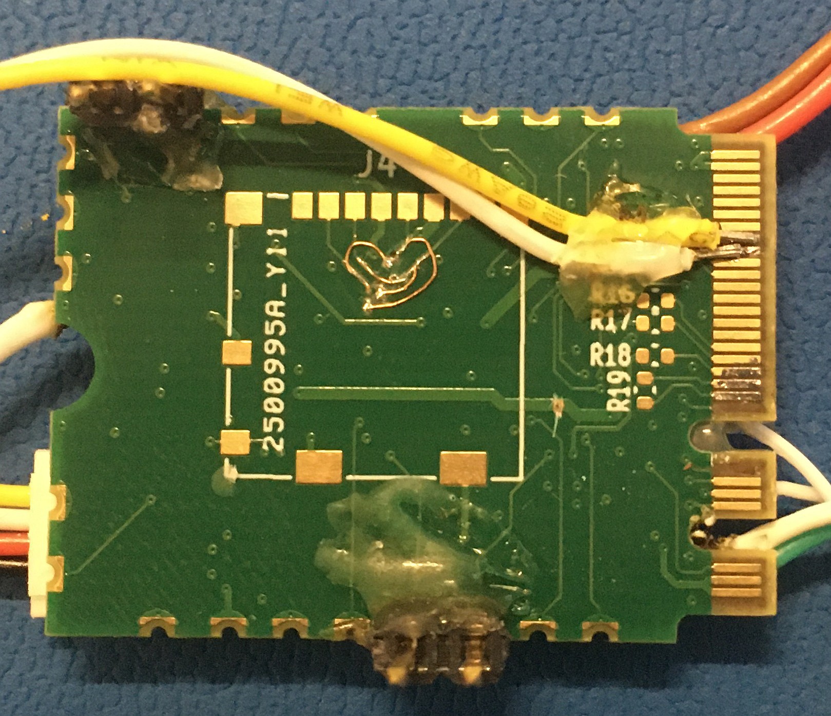
This means 4 cut traces and 4 wires. In the end nobody will know because the wires will be hidden under the SD card holder. Just a few pictures to document the process:
Cut trances and wires already attached. I used 38 gauge magnet wire, which is perfect for this kind of re-work as the insulation melts away. No wire stripping required.
![]()
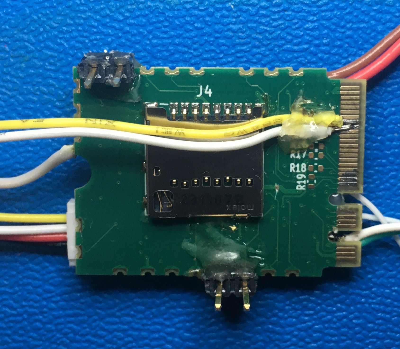
Then the wires got nicely covered with Polyimide for protection
![]()
And the uSD card holder soldered to the board.
![]()
![]()
Next, a trip into software land and trying to talk to the uSD card. I am going to try the Arduino SD library and [Greiman]'s SdFat library. I learned already that the maximum size for FAT32 file-system is 32GB, everything larger needs to run with exFAT. I will find out soon.
-
Poor-mans version of the castellated pins
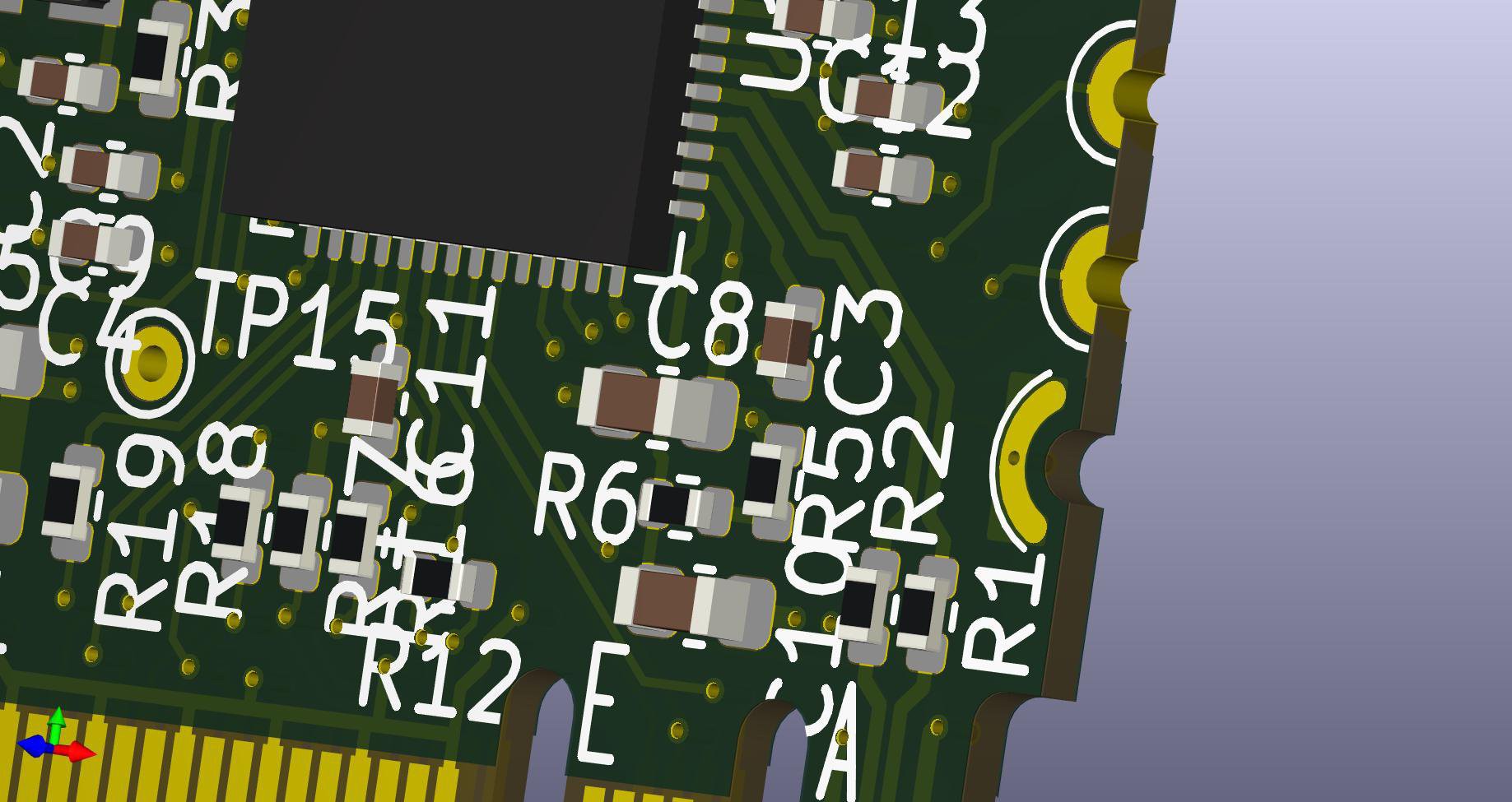
11/16/2024 at 03:07 • 0 commentsSince a long time I had the idea to simulate castellated pins on a board edge to get around the pricey options to do it as intended by your PCB house of least suspicion. My idea was to have the PCB outline indented by half circles and add a curved pad on top and bottom connected through one or more vias. Wires or pin headers could be soldered to either pad. To solder the board on a prepared carrier footprint ( ESP32 module style) would probably need some extra wires, but that was not the intend of this board anyways.
Here is an image how the 2 pad styles look in KiCAD (please ignore the silkscreen, this layout was far from finished). I probably could have moved the half pad closer to the board edge.
![]()
After receiving the boards, I tried to solder pin headers to the pads and ran into several problems. The board was only 0.8mm thick, so there was not much support. With the plastic body on one side, I did solder only the opposite pad to the pin which did not give enough strength. I tried to use hot glue to fix the connector to the board but still managed to rip off pads very easily. Some more pictures of the whole mess.
![]()
![]()
![]()
Overall it was more pain than useful. I would give this idea a -1 out of 11, would not recommend.
-
Current state of Integration
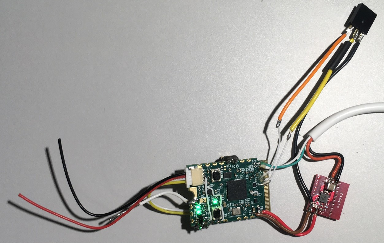
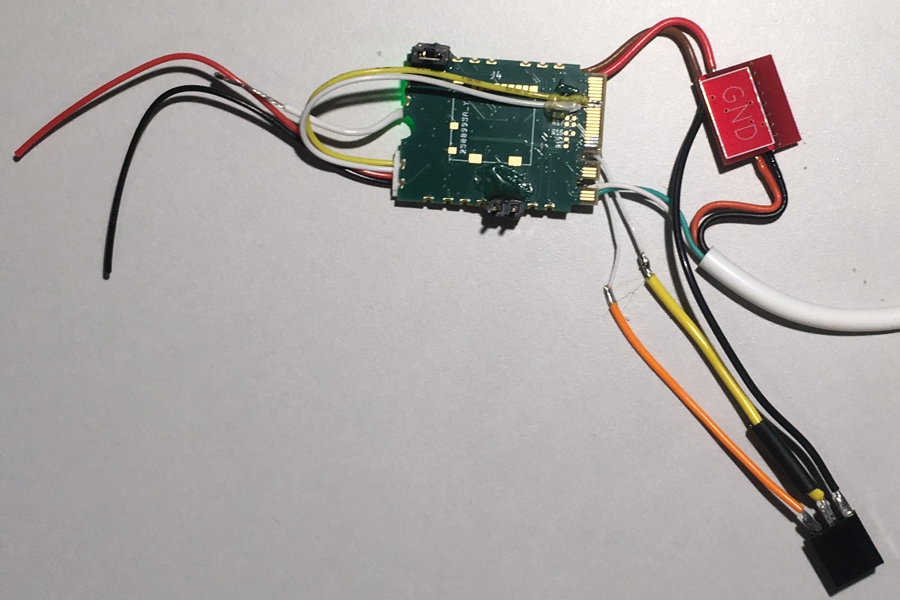
11/07/2024 at 02:39 • 0 commentsAs it happens too often, this revision 1 board has its issues. With my RadXA ROCK 3A SBC not arrived yet, I was going for the fly-wire test approach.
USB and power through an external 3.3 V regulator are working flawlessly. Power LEDs are on and the user LED is blinking away. Nice! UART on the m.2 and on GPIOs are doing simple loopback and the USB/UART is running a simple command line already.
Things that did not work out of the box: I2C (of course). I should pay more attention to the pin mapping. I cannot use I2C1 at the same time on the m.2 and the QWIIC connector. Also pin4 on the QWIIC is SCL, not SDA. Nothing a few cuts and wires cannot fix. Now I have a loop-back from the m.2 end to the QWIIC connector. One port is master, one is slave. Mint.
More wires will be required to test the uSD card, the SPI signals are connected up-sidedown to the SPI port on the RP2040. Pin mapping again! I blame this one on the schematic symbol, not showing all pin functions.And the castellated holes will get their own log. Some cheap ideas are also bad.
RP2040 RP2350 M.2 Pico
A RPI Pico RP2040 and RP2350A board in a M.2 AE key form factor.


 USB and power through an external 3.3 V regulator are working flawlessly. Power LEDs are on and the user LED is blinking away. Nice! UART on the m.2 and on GPIOs are doing simple loopback and the USB/UART is running a simple command line already.