jeremy.geppert
-
Updated Files
11/11/2025 at 23:34 • 0 commentsV2 of the 3D printed files have been updated.
The pcb version is for the optional PCB
The non-pcb version will work with just an SAO connector and some proto-board.
V2 does away with the PCB snapping into place and relies on the longer clips to hold the board in place while also making the grid work much more solid.
![]()
-
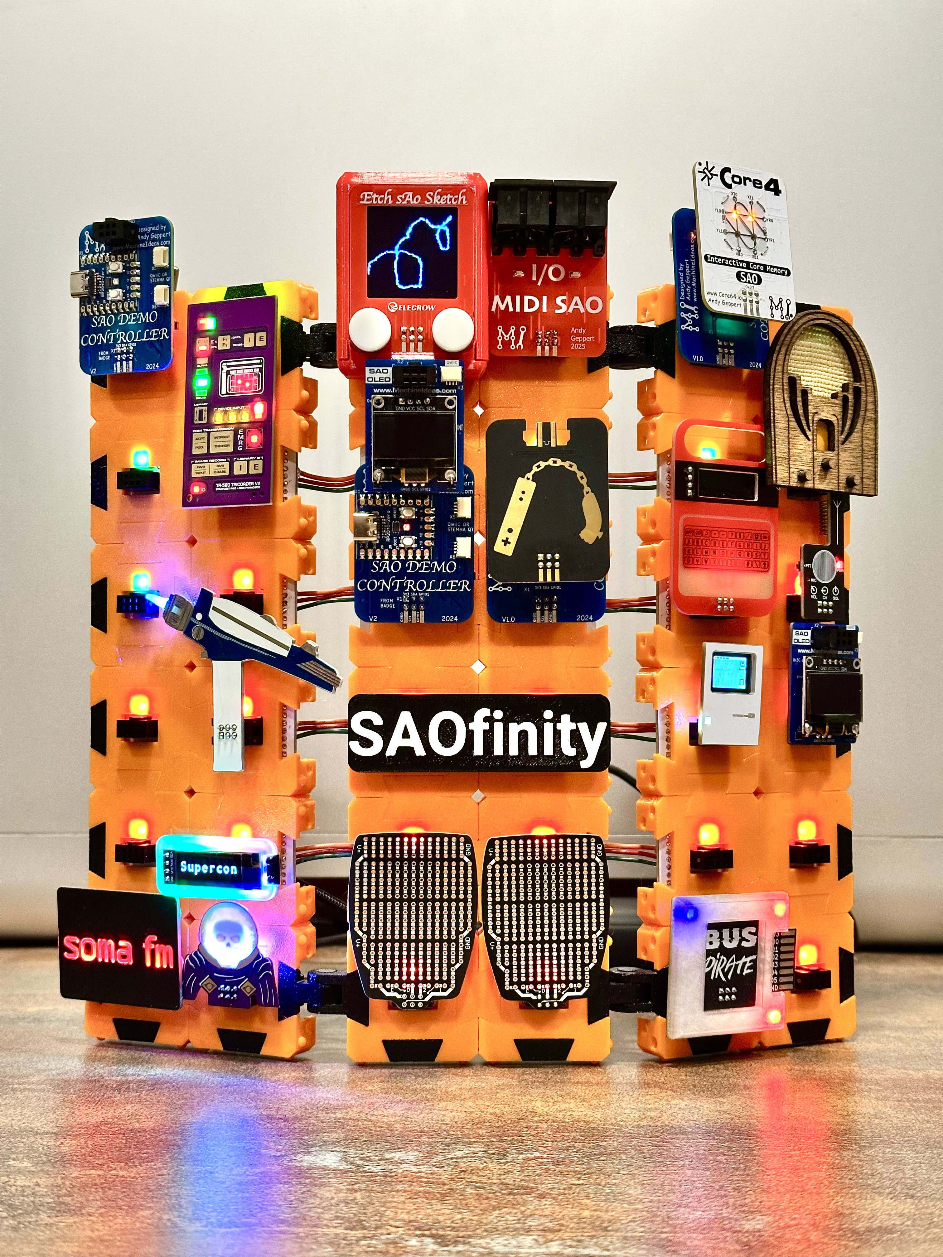
Ready For Supercon!
10/31/2025 at 01:38 • 0 commentsPreview of the demo configuration...
![]()
and a smaller version in clear...
![]()
-
ASSEMBLE: Power Supply for SAOfinity V1
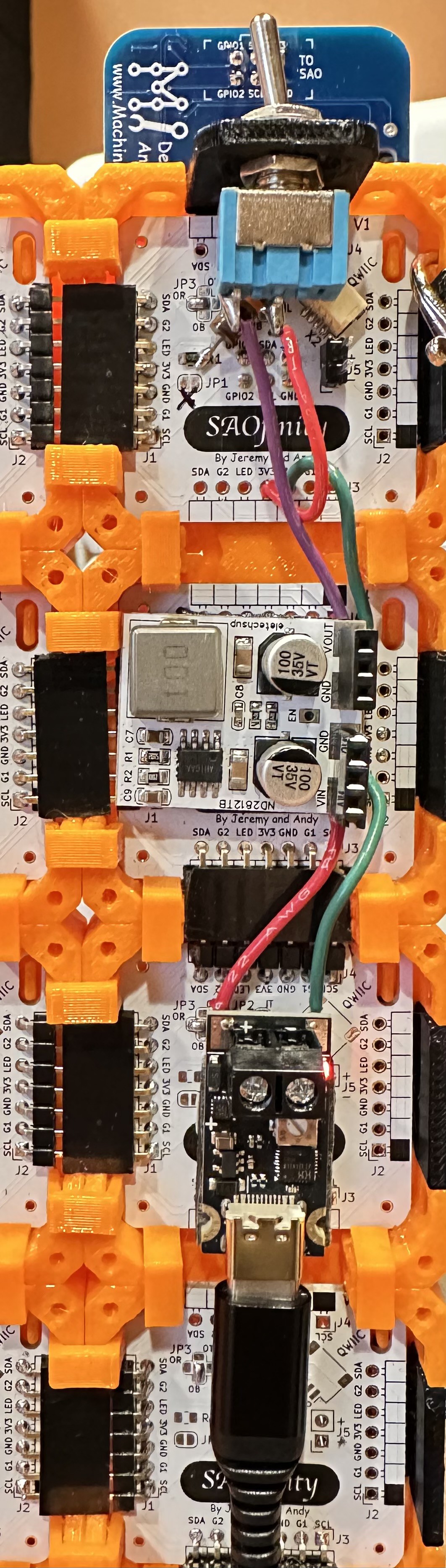
10/30/2025 at 22:34 • 0 commentsHere is what I settled on for power into the SAOfinity system, composed of three parts (bring-your-own-USB C-power pack):
![]()
From the bottom, to the top:
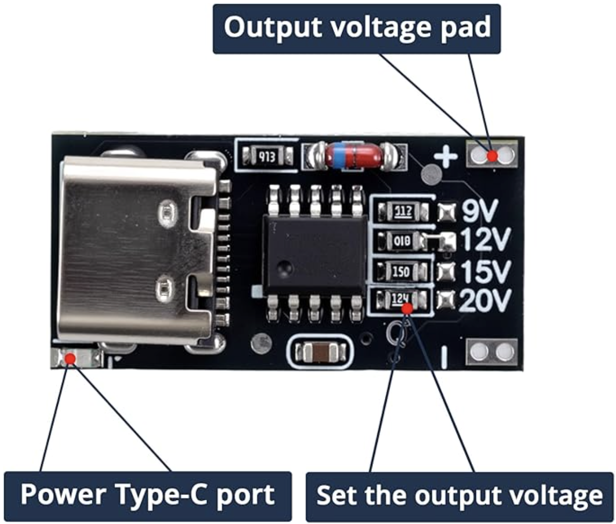
(A) Input starts with a USB C PD board.
If you get a kit from us at Supercon, it'll be a slightly different that shown above.
https://www.amazon.com/dp/B0F8VTTXXT
![]()
The ones I purchased have the output preset at 12V, but any of the output ranges should work fine with the voltage regulator below.
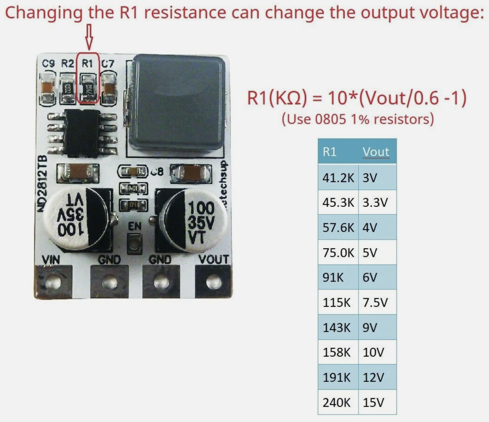
(B) Then to a voltage regulator board.
https://www.ebay.com/itm/285420629162
![]()
This claims to deliver 4 Amps from a 4.5 to 28VDC input, and with a resistor, you can order/change the output voltage to be in 3 to 12V. One of the pictures in the listing shows the resistor calculations. I ordered the 3.3V output version, and changed/included R1 to 51K Ohms, to get 3.66V for a little more headroom on the long power bus. It works well. Maybe ordering these preset to 4V is a better solution in the long-run, assuming all your SAOs can handle 4V.
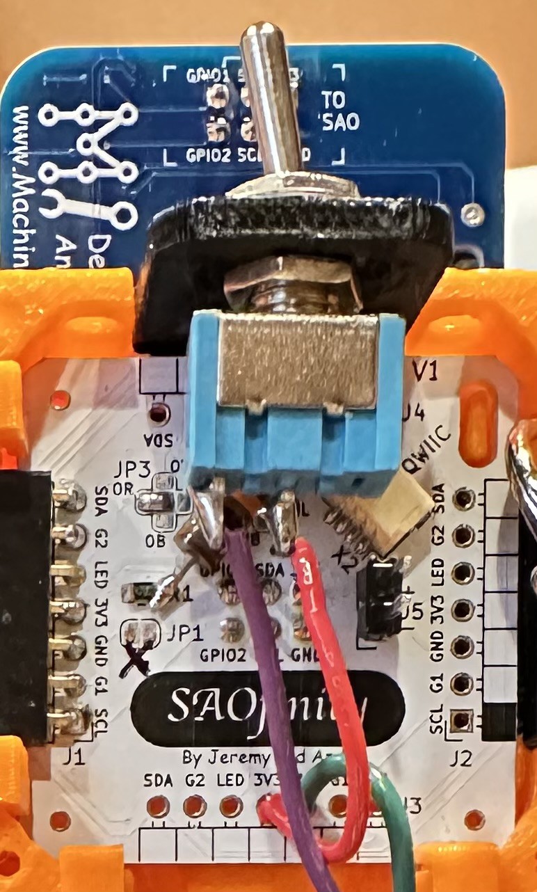
(C) Finally through a power switch.
https://www.amazon.com/dp/B0799LBFNY
![]()
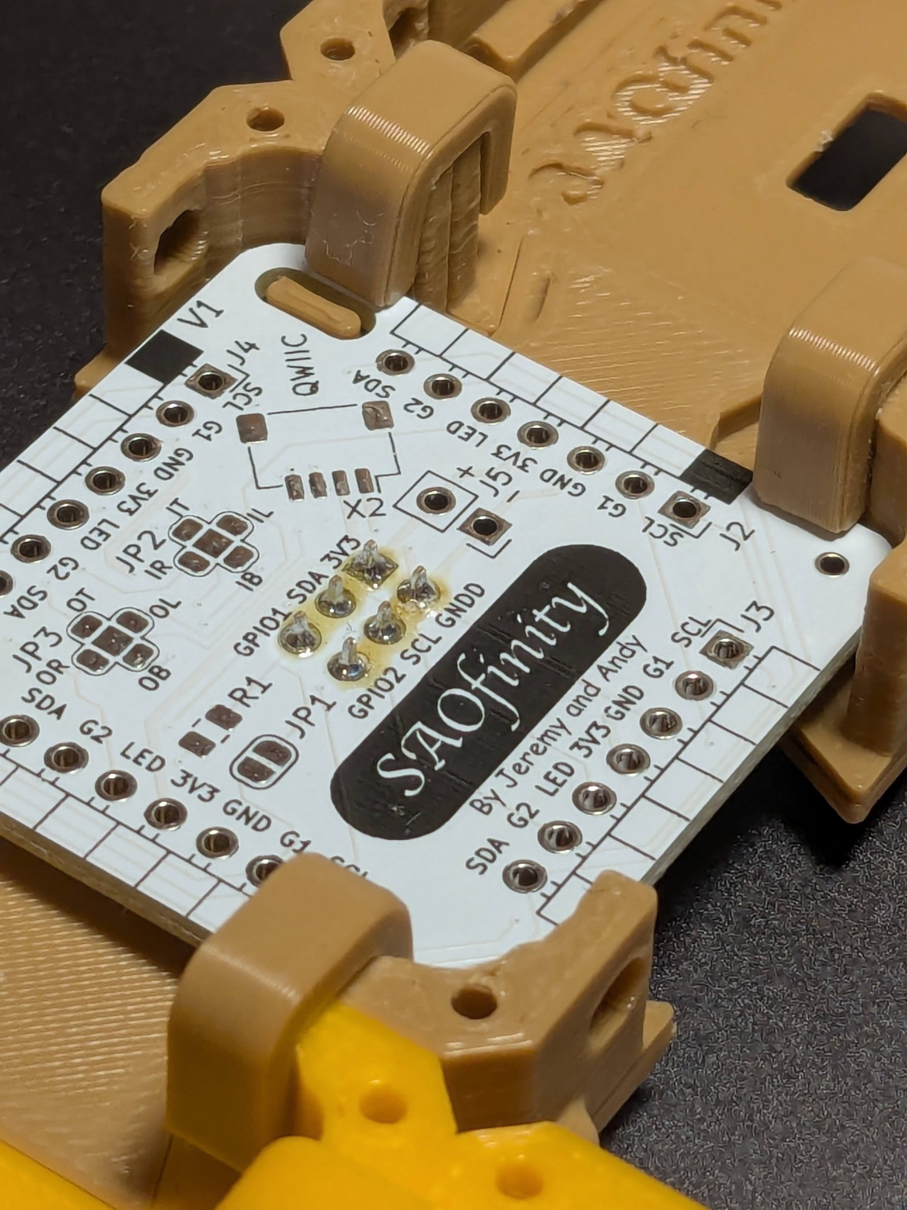
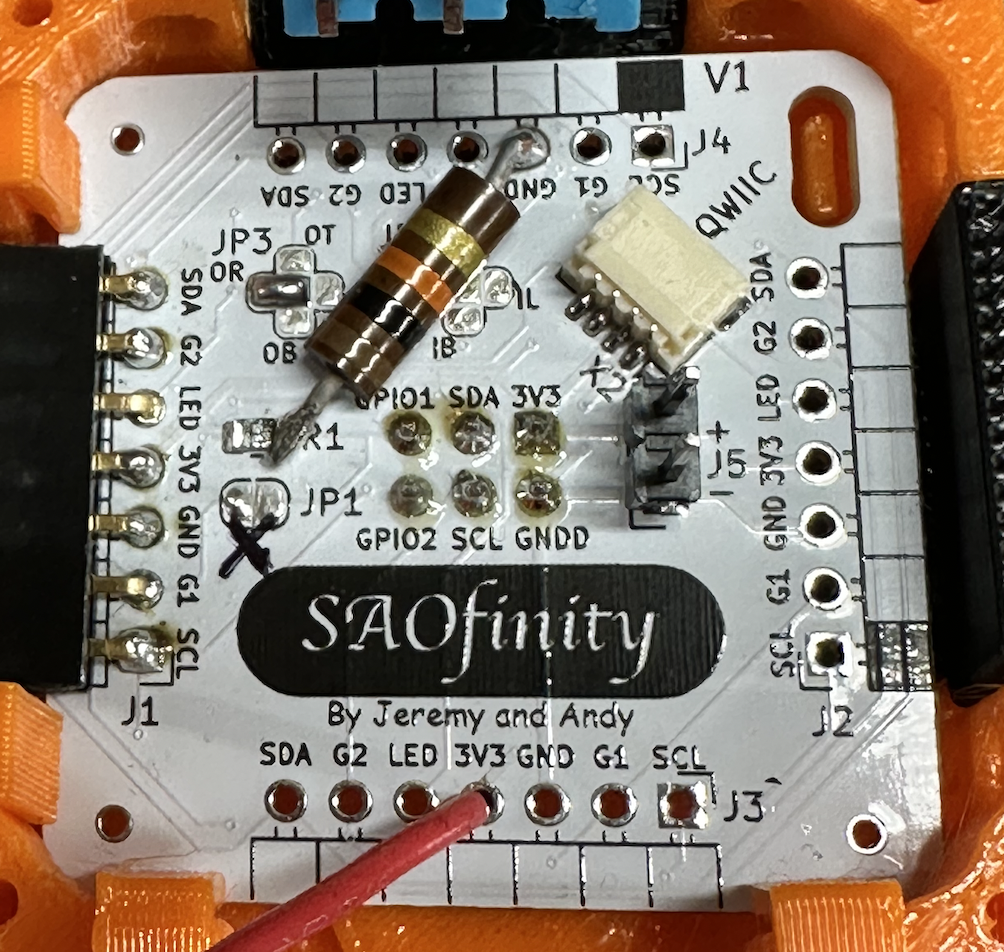
I had to add the power switch at the last minute because I discovered that the voltage regulator output ramps up [relatively] slowly and that causes some problems with the SAO Demo Controller and LEDs on the tiles. Without the switch, several of the RGB LEDs on the tiles would trip out and fail to operate correctly. I also attempted to mitigate that issue by putting a 10K Ohm resistor on the signal line on the back of the first SAOfinity PCB tile:
![]()
And the final final step is routing the switched 3V3 into one of the open 3V3 pins on the first tile. And ground to GND of course. On the PCB, all GND and 3V3 pads are connected together.
![]()
The power switch and SAO Demo Controller (not included - but available) are intended to operate from the first SAOfinitiy tile in the series, which is arbitrarily suggested as upper left, when viewed from the front. This has to do with the suggested signal routing for the built-in RGB LEDs.
![]()
The V1 kits include all of these components, wires, double-sided tape, switch, switch mounting bracket, resistors. And a USB C to C cable!
If all you need is power to the tiles, then you only need to connect the 3V3 and GND from tile to tile. The other connections are all optional. But each board does have a built-in RGB LED, so you'll probably want to connect the LED signal from board to board (in series only!). More on that in the next ASSEMBLE: LED Signal Chain blog entry.
-
Hinges
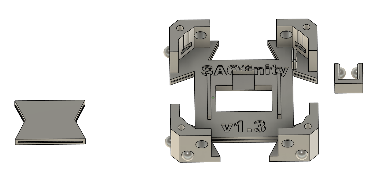
10/28/2025 at 02:04 • 0 commentsCollaborator Andy requested hinges... let there be hinges for infinite display options.
![]()
-
Revisions...
10/23/2025 at 03:06 • 0 commentsWith the PCBs in hand revisions have been made after much collaboration and iterations.
-Standoffs to make sure any pins don't touch the plastic for static concerns.
-"Click-in" corner reliefs to hold the board precisely in place.
-Opened up the SAO connector hole so full contact can be made. (due to the standoffs)
-2 layers of plastic in front of the LED so it can shine through.
-Protrusions in the "bow-ties" and slots in the body for a "click-in" fit.
-Clips to hold the bodies together for wearable or larger portable displays.
I think we have a "final" version ready for mass production.
![]()
![]()
![]()
![]()
-
PCBA Option Unlocked! (updated power supply options)
09/26/2025 at 13:34 • 0 commentsIn collaboration with Jeremy, I just finished the PCB design and ordered some samples for Supercon!
![]()
This effort to add some bling and make the system more "snap together" unintentionally turns SAOfinity into a badge! By designating one tile as the primary control tile, and plugging in an MCU to that board, you''ll be able to control the built-in chain of LEDs, and communicate with the I2C and GPIO on other tiles. I will use the SAO Demo Controller I designed as an example in the next log entry.
FEATURES
- RGB LED: Built-in, daisy-chainable to be controlled from a primary SAOfinity tile board. Allows control of RGB LED as a backlight to the SAO on display on a given tile. Solder jumpers make it flexible!
- CONNECTORS: PCB is ready for right angle 0.1 inch pitch 7-pin edge connectors to eliminate wires. All 7 pins are not required to use the board - just 2 pins for power are sufficient. A third pin enables access to the RGB LED. The other four pins enable I2C and GPIO1&2 connections between tiles
- QWIIC: A spot for you to add a QWIIC connector because that should be a great part of the SAO ecosystem too!
- POWER: Designed to operate at 3.3V for now. Dedicated pads (or a connector if choose) to power your SAOfinity creativity. See below for more details. Bring-your-own-power-source.
![]()
V1 IMPORTANT NOTES ABOUT POWER OPTIONS:
This first version (V1) has two pins for 3.3V power (J5) to be supplied by any 3.3V source. The 3.3V supply is the common voltage rail shared between all SAOfinity tiles when the interconnecting right-angle headers are used. Because most readily available 3.3V sources are lower current, it may be necessary to sub-divide your SAOfinity tile grid into multiple power zones and supply 3.3V power into each zone from a separate 3.3V source. This requires NOT interconnecting the 3.3V power line between those zones through the right-angle headers between select tiles.
NEWEST PLAN 3.3V at 4A from USB C... maybe?
https://hackaday.io/project/195130-ppstrigger-v2-usb-pd-pps-trigger-with-cc-cv
And
https://www.ebay.com/itm/285420629162?var=587342424163
POWER - PLAN A [1.0A @ 3.3-5V adjustable from Micro USB or 1S LiPo]
*** NOT RECOMMENDED FOR V1 ***
Requires resistor mod. Stand-alone battery powered or Micro USB. In the first non-PCB prototype set of 16 SAOfinity tiles, I'm running power from an Adafruit LiPo charger/boost board and battery through the chain of SAOfinity tiles:
- Charger and Power Boost https://www.adafruit.com/product/2465 ($19.95)
- Battery (variety) https://www.adafruit.com/product/5035 ($10-30)
Does NOT need a battery to run from USB port. I think it's OK to run that way - seems to work fine.
I modified the power boost board by changing the output voltage setting to 3.75V (a little bit high for SAO spec but some room for the voltage to sag). R3 has been replaced with a 1.3 MOhm resistor.
POWER - PLAN B [1.0A @ 3.3V from 5-18V or USB C (5V) or 1S LiPo or Solar MPPT-like]
*** SIMPLEST FOR V1 - limited power output though ***
Compared to PLAN A it's better with no mods, lower cost, proper USB C. Power path support. However, it doesn't add any more 3.3V power output capability.
Charge via bq2518. Buck switching regulator TPS62569 (90-95% eff., 3.4-5.5V in, up to 2A if used with proper inductor).
POWER - PLAN C [4.0A @ 3.3V from 4.5-28V]
*** If this delivers as advertised, use with USB C PD selectable voltage board to power MANY tiles! ***
- https://www.ebay.com/itm/285420629162 ($2.50 + $8.00 shipping from China)
Use with one of these:
- Solder jumper selectable voltage rail: https://www.adafruit.com/product/5807 ($6)
- Switch selectable voltage rail: https://www.adafruit.com/product/5991 ($10)
POWER - PLAN D [0.8A @ 3.3V and 3A @ 5V from USB C 5V]
*** NOT RECOMMENDED FOR V1 *** May be for individual tiles powered by future (V2) 15V rail.
STM LD1117 linear regulator (heat producer) drops USB C 5V input to 3.3V @ 800 mA (and passes through 5V at 3A):
- PCBA https://www.digikey.com/en/products/detail/artekit-labs/AK-USBSUPPLY-C/22543800 ($8.81)
- IC (15V max input) https://www.digikey.com/en/products/detail/stmicroelectronics/LD1117ADT33TR/669253 ($0.32/ea @ 100pc)
POWER - PLAN E [2.0A @ 3.3V from 5V header pins]
TPS62827 converts 3.4-5.5V input to 3.3V @ 2 Amps practically (3A peak):
- PCBA https://www.adafruit.com/product/4920 ($7)
POWER - PLAN F [1.2A @ 3.3V from 4.5-21V header pins]
MPM3610 converts 4.5-21V input to 3.3V @ 1.2 Amps. Ideal for use with high voltage USB C PD rail.
- Board https://www.digikey.com/en/products/detail/adafruit-industries-llc/4683/12822323 ($6)
- IC https://www.digikey.com/en/products/detail/monolithic-power-systems-inc/MPM3610AGQV-Z/5292908 ($1.47/ea at 100pcs)
POWER - PLAN BY Y-O-U!
Use whatever makes sense from your parts bin. Just keep the voltage rail near 3.3V. Remember, you can split up the SAOfinity grid into multiple sub-sections and provide adequate power to each sub-section. You don't have to provide a single power input for everything.
POWER - FUTURE VERSION
To enable larger load capacity, I think it makes sense to move the interconnection power rail up to a higher voltage driven with a USB C PD socket. Allowing the user to select the PD voltage is a bonus feature. Then step-down the voltage to 3.3V at every single SAOfinity tile. Examples:
- USB C PD input 5-20V main input to first SAOfinity tile in the series (secondary PCBA)
- Solder jumper selectable voltage rail: https://www.adafruit.com/product/5807 ($6)
- Switch selectable voltage rail: https://www.adafruit.com/product/5991 ($10)
- Regulated to 3.3V at each SAOfinity tile
- 4.5-21V in to 3.3V @1.2A output! https://www.adafruit.com/product/4683
- LDO 20V->3.3V @0.5A ($0.71/ea @ 100pcs) https://www.digikey.com/en/products/detail/stmicroelectronics/KF33BD-TR/1038077
-
Skittles!
09/22/2025 at 03:13 • 0 commentsI wanted to see what a bunch of random colors would look like together with these grids. Did I just create art? Probably not.
![]()
-
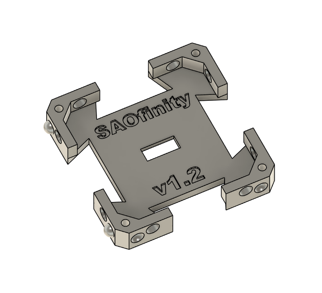
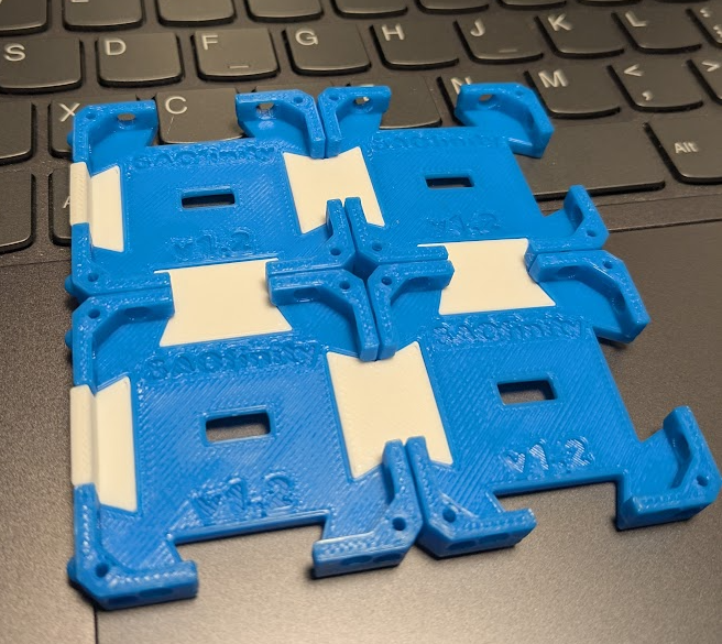
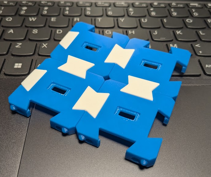
V1.2 Balls and Bosses
09/22/2025 at 03:06 • 0 commentsAfter some brainstorming with my brother on improvements based on some field testing here is the current iteration:
![]()
Note the addition of alignment "balls". Convex and Concave spheres to keep things in the same plane.
Also, M2.0x5.00 bosses for attaching a backplate or other things with screws.
![]()
![]()
-
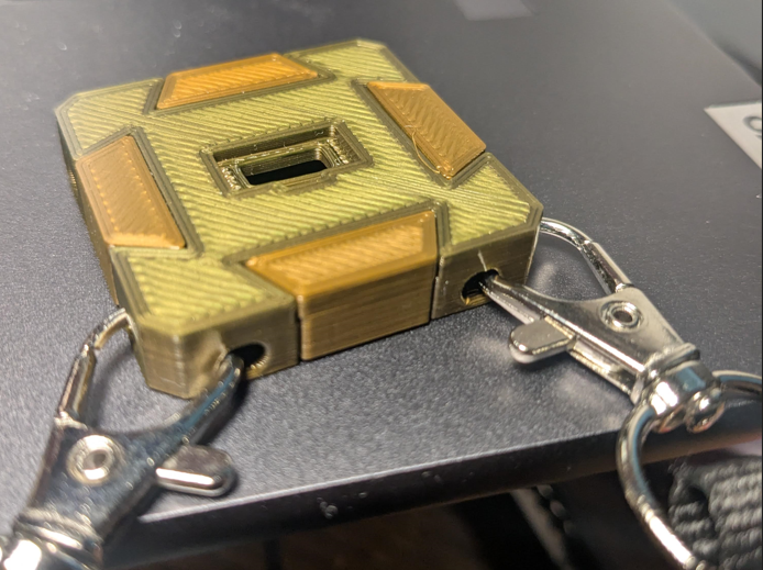
Unintentionally Wearable
08/10/2025 at 11:57 • 0 commentsThere are holes on the edges for routing wires which happen to work with lanyards.
![]()
SAOfinity
A modular, low barrier and inexpensive way to display all your SAOs Infinitely!