-
Home sweet housing
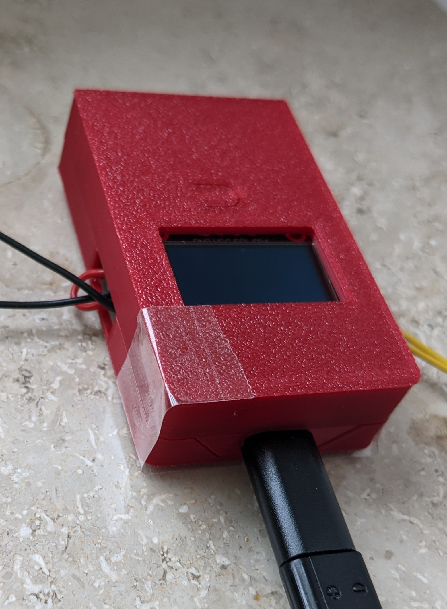
01/09/2026 at 09:28 • 0 commentsOnly the housing was left. A bare PCB on the window bench does not appeal my wife.
Thus, a housing was to be created. The buttons are functioning with a smal cutout that bends down.
And here it is after some trouble with false measurements and FreeCAD.
![]()
Unfortunately, some tape is needed to hold the two shells together. Designing clips is the next level. I am not there yet.
-
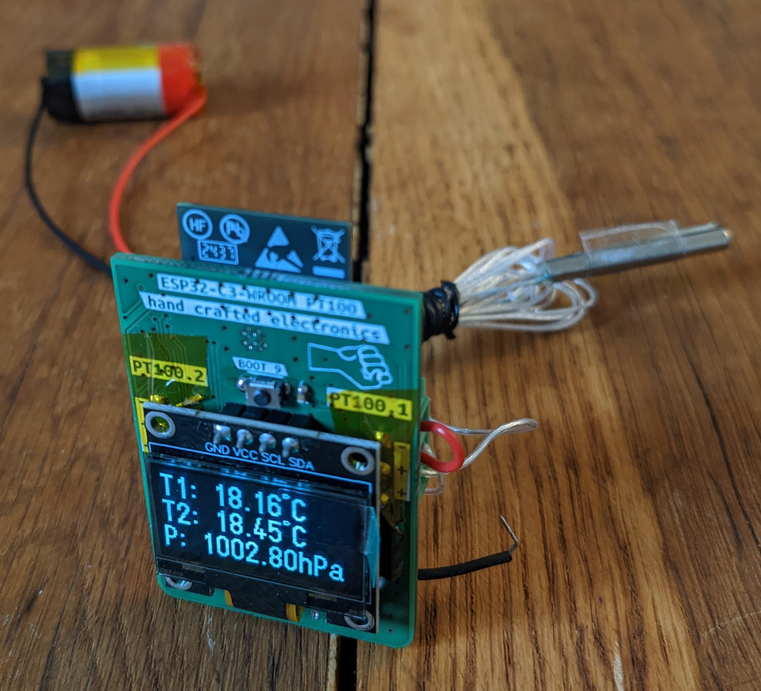
MQTT + OLED now active
11/28/2025 at 13:03 • 0 commentsAfter many errors and a bit of code restructuring, the temperatures and pressure are finally displayed correctly. The OLED now updates once per minute with the latest readings. Every 15 minutes, the device sends an averaged value (covering the last 15 minutes) via MQTT to my Raspberry Pi broker.
As mentioned in a previous post, the broker and topics are customizable in the web interface.
So far, everything works exactly as expected—and I’m really happy with the results! :)
![]()
-
Battery Charger
11/19/2025 at 16:31 • 0 commentsMy fault... Who else?
I discovered the issue: I had soldered the DW01A protection IC rotated by 180°.
After replacing the chip—and swapping the 8205 dual MOSFET as well, just to be safe—the battery charger now works exactly as expected.
The controller can correctly read the charging status: charging, full, and discharging all work. Only the “battery not connected” state is still not detected properly.
Unfortunately, the TP4056 attempts to charge even when no battery is connected, which causes the status pins to toggle continuously. I had hoped they would simply stay low in this condition. I definitely don’t want to detect a toggeling status pin....
The battery voltage is now correctly measured and advertised in the web interface.
By the way: resoldering the barometer with hot air also solved for the short on the lines. The barometer is now working perfectly!
-
First Prototype
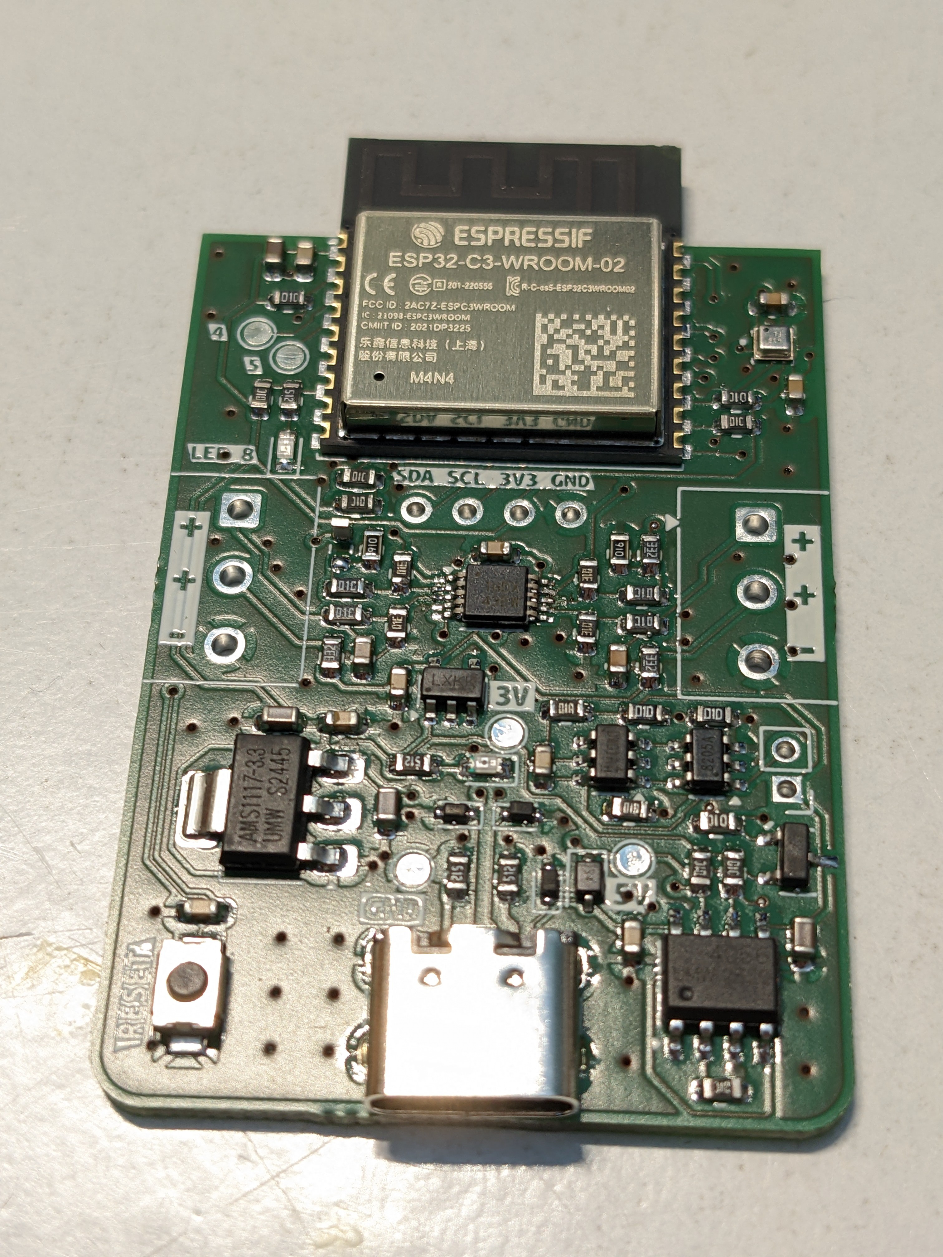
11/15/2025 at 11:29 • 0 commentsAssembly
The PCB finally arrived, and I assembled the first board.
I was initially worried about the quality of the solder paste application through the stencil. First, there’s the USB-C connector, which absolutely must be soldered perfectly—there’s no way I could fix that with a soldering iron. The pitch is far too fine.
The second concern was the barometer chip: it’s tiny, and any rework would only be possible with hot air.Surprisingly, applying the solder paste went quite well. Unfortunately, the pins of the barometer were completely shorted.
Nevertheless, I placed all components and “baked” the board on my cooktop. This is a proven method for me and works very well. 😄
After soldering, I checked most critical signals for shorts to GND or VDD.
Only two issues showed up:
-
The op-amp had shorted pins.
-
The barometer had SCL shorted to 3.3 V, meaning I²C would not work. The OLED wasn’t assembled at this stage.
Apart from that, everything else looked good!
Can you spot the tombstone?![]()
First Power-On
Next, I supplied 5 V from my bench power supply with a 100 mA current limit. The board powered up, and 3.3 V was present.
Then I connected it to the PC to flash the firmware. As hoped, the controller was recognized immediately, and the Arduino IDE connected without issues. Flashing worked too.
Then the problems started.
Several things didn’t work—or appeared not to work. After many flashing attempts, I finally reverted to the very first firmware version. Somehow I had made the code worse over time.
With this restart of the firmware, the controller successfully starts an access point. The Wi-Fi credentials can be entered via the browser interface and are stored in flash. After a reset (which still doesn’t work correctly in software), the controller connects to the configured network.
Calibration with precision resistors also works. However, the op-amps do not output matching values for the same calibration resistor. After connecting real PT100 sensors, the first temperature readings were not too far off. I calibrated them in an ice bath, so in theory they should now always match.
But they don’t.
Maybe the sensors are too cheap—after all, I bought them on eBay…Testing the Battery Charger
Using my power supply, I injected around 4 V to simulate a battery. Measuring at the 5 V test point, I got only 3.4 V—quite a drop. At the 3.3 V test point, only 2.4 V remained, and the controller wouldn’t even start.
I suspect the AMS1117 isn’t suitable for operation from battery voltage because its dropout voltage is simply too high.Coming Up
Firmware improvements are ongoing. Some features—like MQTT—are still missing.
The hardware needs several corrections. I’m also considering adding a buck/boost regulator so the full battery voltage range can be used as the input.
-
-
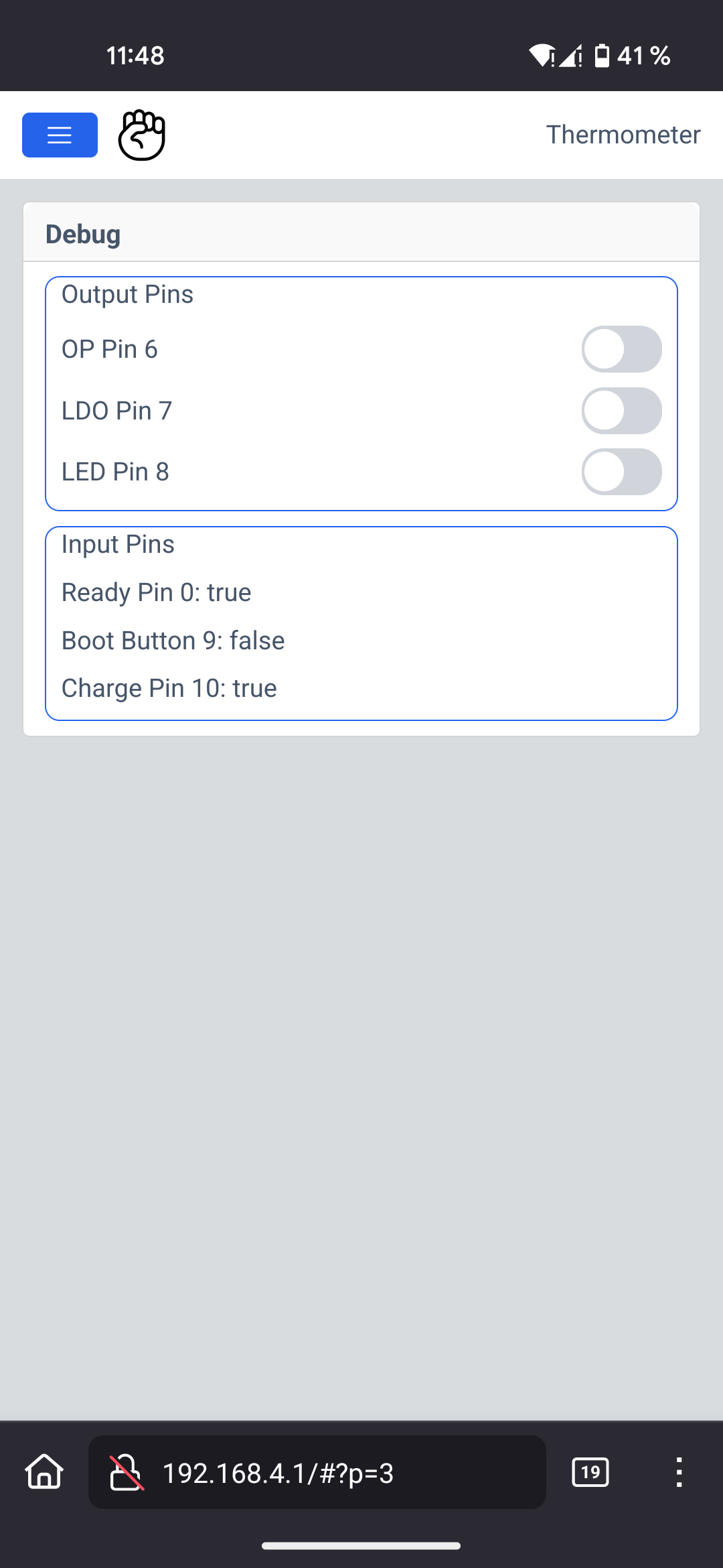
Debug Interface
10/31/2025 at 12:35 • 0 commentsI came up with a new idea: during hardware development, it’s extremely convenient to have full control over all input and output pins.
Normally, this kind of control requires reflashing the firmware or reassigning functions in software—for example, mapping a button to a specific GPIO. If you’re using a debug probe, you can manipulate pins directly while the controller is running. However, I’m working in the Arduino IDE, so that approach isn’t practical.
My solution builds on the HTML interface I described earlier. I simply added a new page with toggle buttons to control the output pins and text indicators to display the logic input states.
The result looks like this:
![]()
-
Additional Features
10/26/2025 at 12:20 • 0 commentsDid I mention that the heart of the device is an ESP32-C3? Well, now I have. I’m using the WROOM module since it features castellated pins, making it easy to inspect solder joints and probe signals directly at the pads.
The device is designed to support different hardware and software variants. More on those in a later update.
Battery Operation
A key requirement is battery-powered operation. I want the device to run from a Li-ion cell—either reclaimed vape batteries or old power-tool cells that deserve a second life. For charging, I chose the well-known TP4056. Thanks to [Chris] CRAPi2040 logs, I learned that a PMOS transistor is preferable over a diode when powering the system via USB while still charging the battery. The chip’s CHRG and STDBY pins are routed to the controller. I skipped dedicated LEDs for status indication the battery state is visible through the OLED or the web interface anyway.
The battery voltage is monitored by the controller via a voltage divider. I’m curious how well this works at low battery levels. The ADC reference is specified at 1100 mV, though it may drift slightly before the device eventually powers down when reaching 3V.
Additional safty comes from a battery monitoring IC that disconnects the battery when the voltage is to high or to low.
Optional Sensors
I added a footprint for the BMP388 barometric pressure sensor from Bosch. I’ve never worked with it—and haven’t checked library availability either—but footprints are free, so adding one is simply extra potential without any cost.
Buttons & User Interaction
The device includes a reset button tied to the reset pin and a boot button on GPIO9, which is a strapping pin. I likely won’t need it for flashing, since I intend to program the ESP32-C3 via USB. Holding the boot button at power-up would also enable serial download mode, if ever required. Additionally, the button doubles as a user input—possible use cases include waking the device from deep sleep or re-activating the OLED display after it powers off automatically. The software will make good use of it.
-
Calibration and configuration over AP
10/25/2025 at 16:05 • 0 commentsOne important feature I want to achieve is the configuration of the Wi-Fi network the device should connect to. Similar to many smart home devices, it will provide its own access point for setup. However, unlike typical IoT devices, mine does not require internet access—nobody needs to see my temperature data (and they shouldn’t!). Everything will be accessible locally via the AP.
Mongoose.wz offers a very nice online tool to design a professional-looking HTML interface for free, if it is open-source. After a bit of a learning curve, I finally figured out how to use the API and library properly—and now it works beautifully.
System Overview
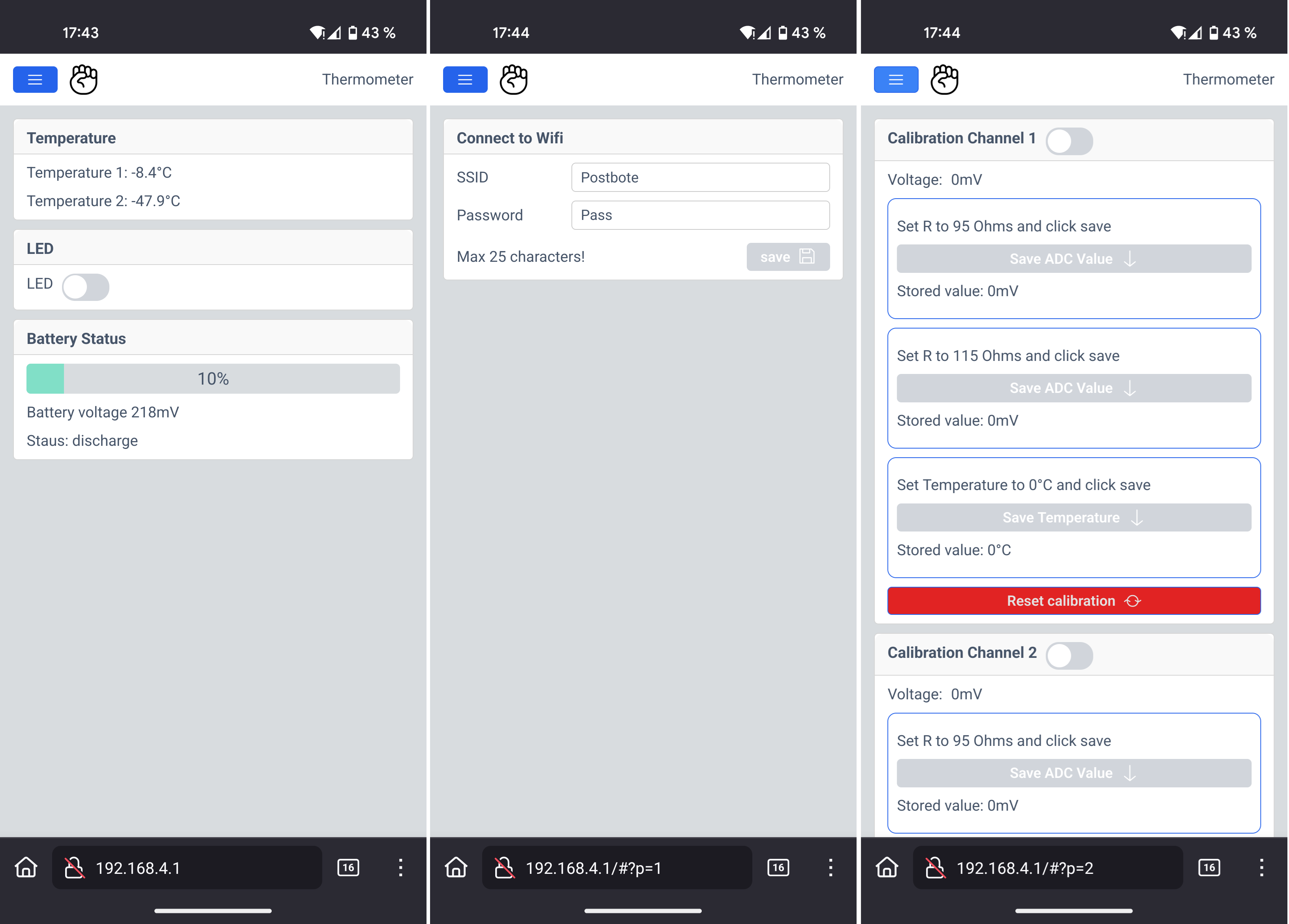
When the device starts up, it first tries to connect to a known Wi-Fi network. If that fails, it automatically starts an access point. You can then connect to it and open its default IP address—usually 192.168.4.1—in your browser. On Android with Firefox, initial loading can take a moment, but eventually the page appears.
The main page shows:
-
Both temperature readings (and later possibly ambient air pressure)
-
Battery status
-
A toggle button for the onboard LED to verify functionality
Wi-Fi configuration
Using the menu (“burger” icon), you can access the Wi-Fi configuration page to enter network credentials. These are stored in emulated EEPROM for persistent access. Even if the network is currently unreachable, the saved credentials remain visible—intentionally a feature.
Calibration Page
The third page provides calibration options. Each channel can be calibrated individually using:
-
Two known reference resistors
-
A PT100 measurement at 0°C
Both channels can also be reset independently. When calibration mode is enabled via the slider, previously stored values are shown for reference. Calibration data is also saved in emulated EEPROM.
With the Mongoose Wizard, the interface can be easily expanded and customized as the project grows.
![]()
-
-
Precise PT100 measurement
10/25/2025 at 15:38 • 0 commentsDealing with temperature measurements might sound simple—after all, temperature is part of our everyday life. But obtaining precise measurements is a different story.
There are several pitfalls: component tolerances, ADC variations, changing battery voltage, environmental temperature shifts, and the imperfections of the sensor itself. Even the circuitry that connects to the sensor can introduce errors.
So how do we handle all of this?
The PT100 Sensor
The PT100 is made from a platinum alloy, providing a nearly linear resistance-to-temperature relationship across a wide range. These sensors typically operate from extremely cold to extremely hot temperatures—far beyond the range humans normally experience. Since I only need to measure between –20 °C and +40 °C, the sensor is sufficiently linear in this region. That means I can avoid complex conversion formulas and still achieve good accuracy.
But does this already introduce some inaccuracy?
The Circuit
I chose a Wheatstone bridge, as it is a highly accurate method for measuring small resistance changes. There are dedicated PT100 measurement ICs with SPI interfaces that can deliver temperature values directly, but I wanted to keep the design as cost-efficient as possible. I’m using such an IC in my mock-up as a reference for comparison.
For amplification, I selected the TLV9002S operational amplifier. Its low offset voltage can be handled in software, and it provides two channels plus individual shutdown pins—useful for reducing power consumption in a battery-powered design.
The PT100 is connected using a 3-wire configuration. This may be unnecessary with short cable lengths, but I want to evaluate the potential benefit.
Component Tolerances
All bridge resistors are 0.1%, which already helps improve accuracy.
ADC
Espressif microcontrollers are not known for their highest-quality internal ADCs. However, with proper calibration functions (beyond the standard
analogRead()performance), results can be significantly improved.Some deviation may remain—but we’ll see how well we can correct it with some additional calibration.
Varying Battery Voltage
Battery voltage fluctuations can distort resistance measurements. To mitigate this, I supply the measurement circuit from a regulated 1.8 V rail. The ADC then uses programmable gain to utilize the ADC range more effectively.
Even with early tests using 1% resistors, a basic op-amp, and simple code, the results are promising.
Calibration
For calibration three measurements are necessarry:- A low temperature (like -10°C)
- A high temperature (like 30°C)
- At 0°C.
To emulate the temperature I make use of a known resistor. With the PT100 formula I can calculate the temperature at a given resistance.
The software calculate the linear graph y=mx+b or T=mU+b. Now every measured resistance can be converted to a temperature and all components that does not change (thus soldered) are part of the calibration.
The relative temperature (the chaning resistance) is now correct.
But one error remains: The absolute temperature. To calibrate to a known temperature there is only one method available without expensive equipment: Ice water. It should have 0°C. If the sensor is in this water the absolute temperature can be calibrated. More precise the sensor element with its tolerances is calibrated. The taken value from the ADC can be substracted from the final temperature calculation.
All together should give a precise measurement.
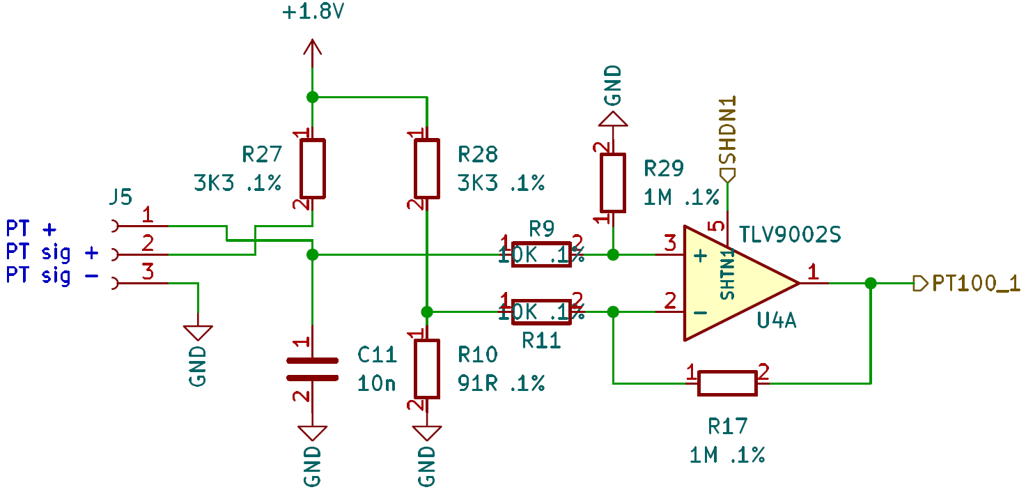
Here is the Wheatstone bridge I’m using:
![]()
R10 sets the minimum temperature (91R ~-25°C). R27 and R28 are current limiting resistors and part of the bridge. R17 and R29 sets the amplification of the difference amplifier. 1.8V ~ 45°C.
2-Channel PT100 Sensor
Measures up to two PT100 Sensors, shows on display, broadcast over MQTT, configure over AP