alexw
alexw-
Pogo pin board replacement
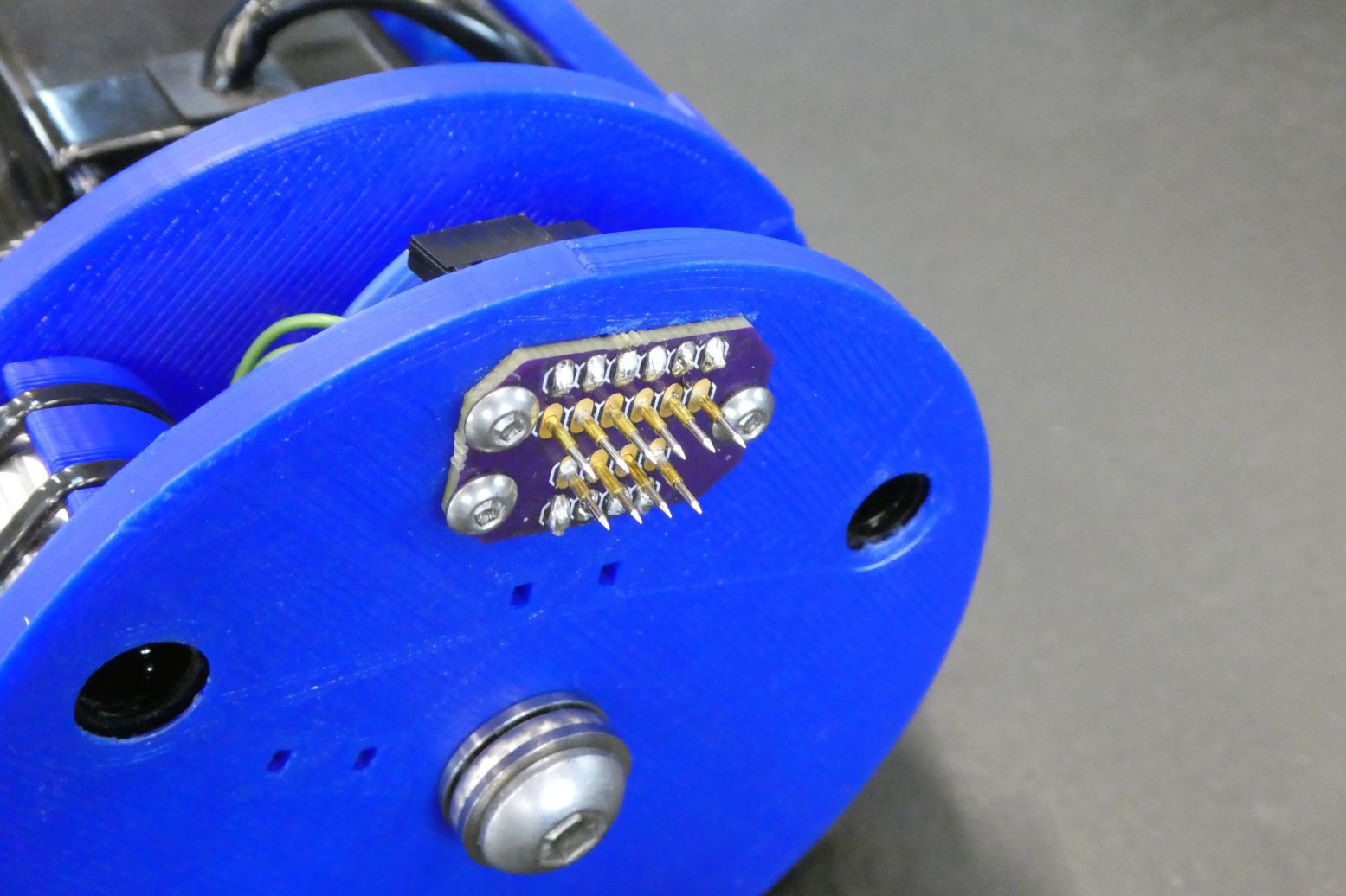
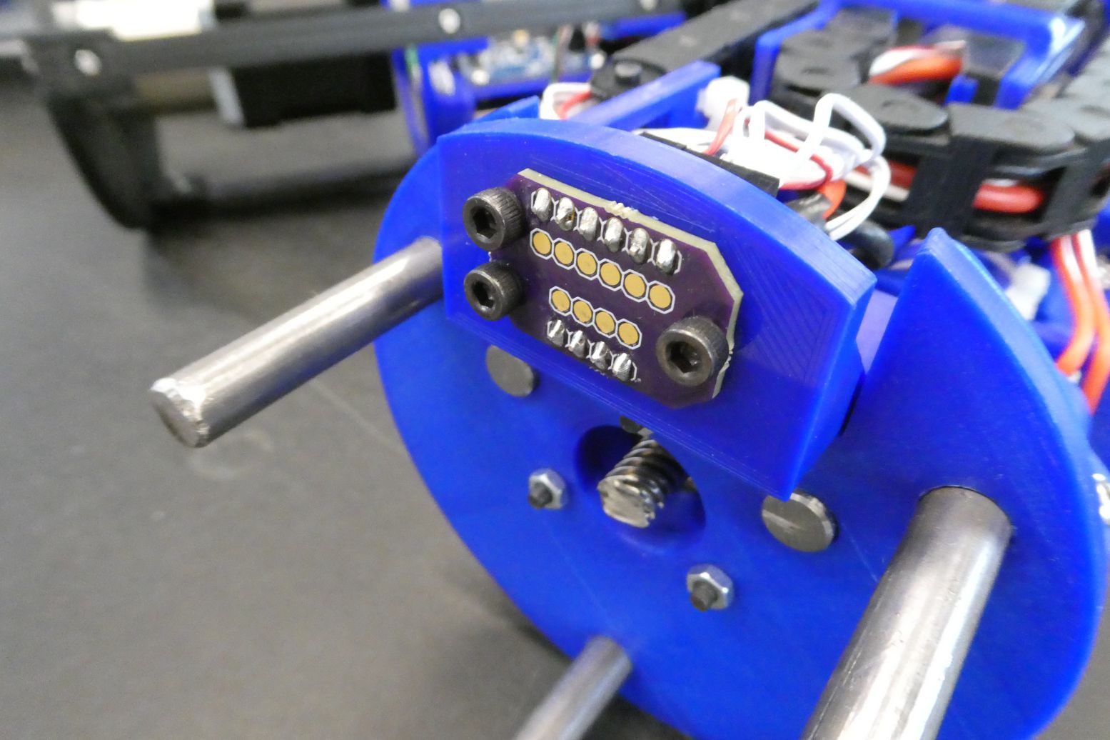
03/07/2018 at 19:56 • 0 commentsThe glider has 2 physical sections internally, the first is the buoyancy engine section and the second is the control boards and the pitch mechanism. The current design (below) uses pogo pins and a pair of boards to electrically connect the two sections, however this has two main downsides.
![]()
![]()
The first problem with the pogo pins is that they use a spring mechanism in order to ensure a reliable connection, this causes the two sections of the glider to be pushed apart when the glider is assembled, which reduces the reliability of the connection. The other issue with this connection type is that the travel of the pogo connectors is only a few mm, which means that the rest of the glider must be aligned to within a couple of mm - the current solution to this is the sliding mounting bracket of the pogo connector PCB.
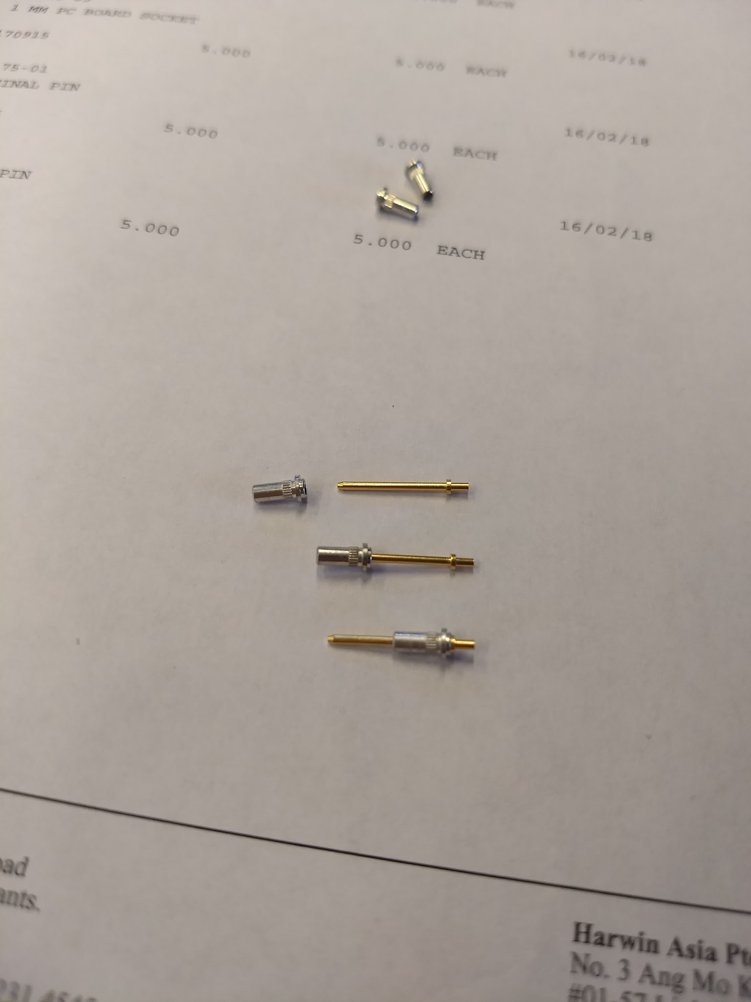
With this in mind, the ideal connection would be one that does not have a spring contact and has ~10mm of travel. After having a look I was able to find the PCB contacts from Harwin that do exactly that, namely the H3169 and H2170 connectors.
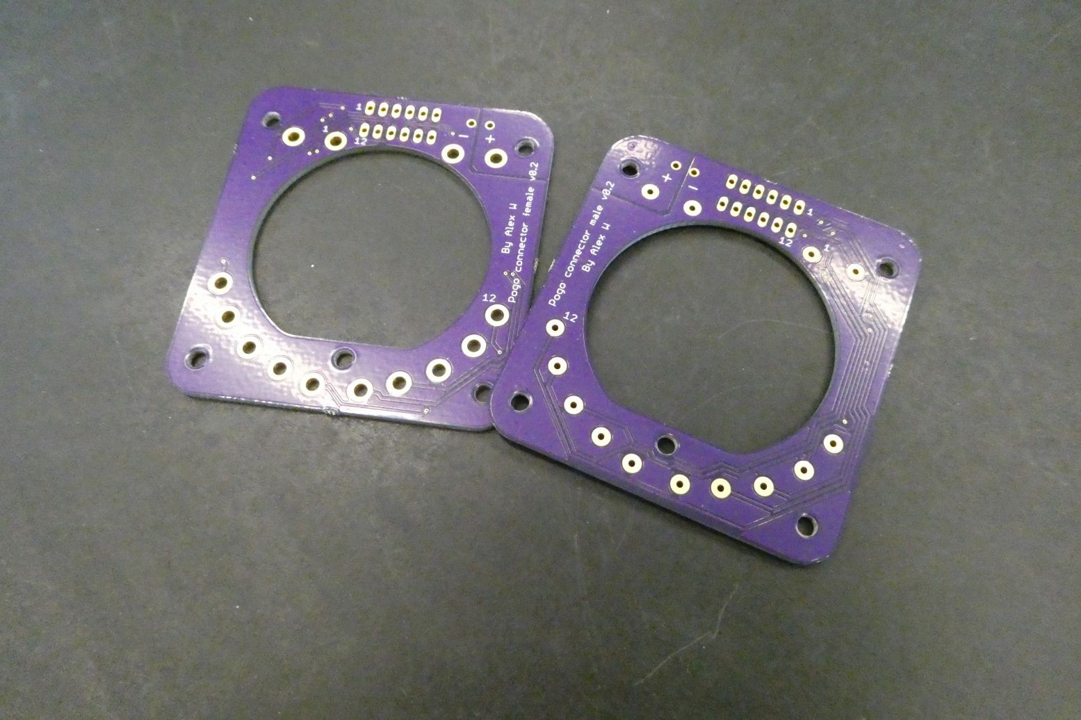
I ordered some sample connectors and they came through and were a perfect match for what I wanted, so I went ahead and purchased ~20 more connectors and designed some boards in Eagle for the two sides of the connector. Below is an image showing that the connectors in varying positions, all with solid electrical connections.
![]()
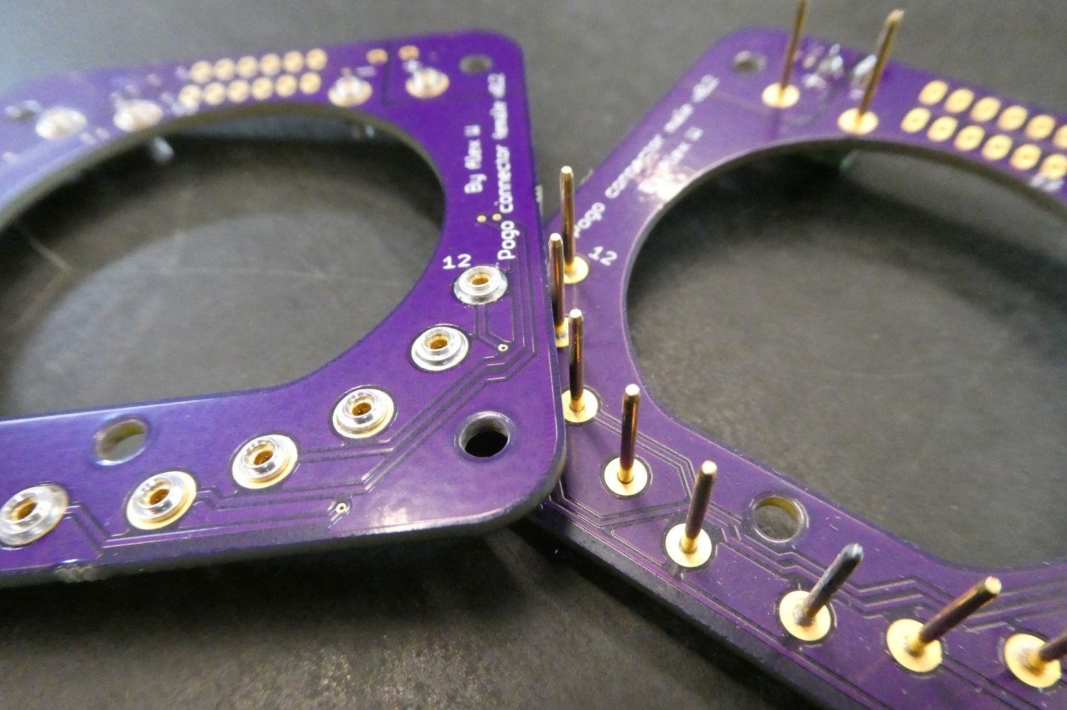
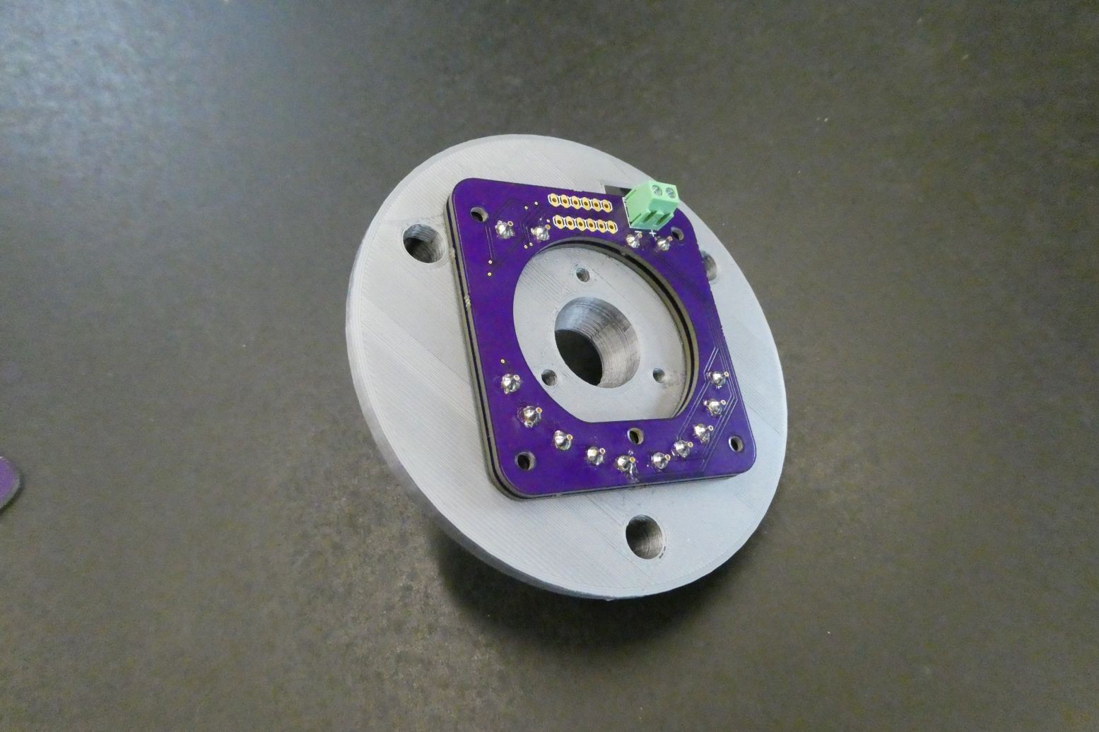
I designed some updated boards for the ordered the PCBs through OSHpark and a massive shoutout to Drew (@pdp7) for providing great customer service and making sure I got my boards within a week. Below are some images of the boards and what they look like with the PCB connectors attached.
![]()
![]()
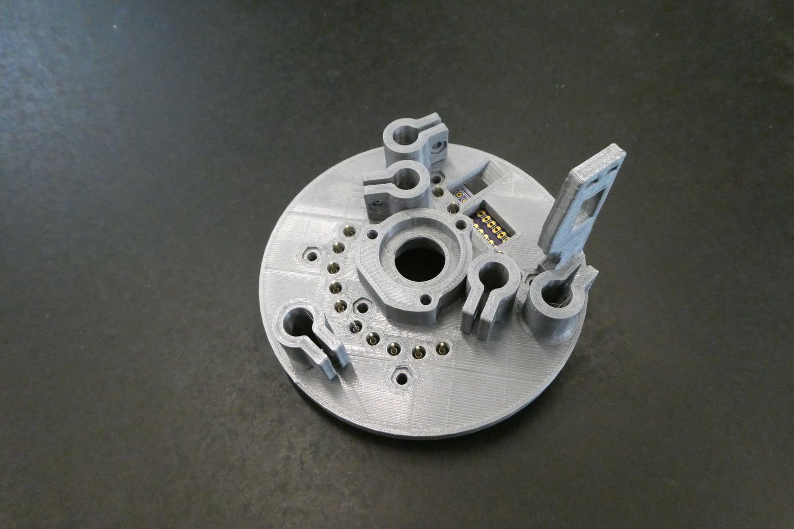
This new configuration also more equally distributes the force of the contacts through the plate, as opposed to on the small section at the top. I designed and printed an updated PCB mounting bracket and you can see how the board fits in-between the alignment rods:
![]()
![]()
Although using Onshape was an interesting experience, I am now transitioning to Solidworks for the design of the glider, but understanding that not everyone has access to Solidworks, I will still be providing the STL files so anyone can download and print the parts. The PCB files are also in the Dropbox development folder.
-
Assembled control board and backend update
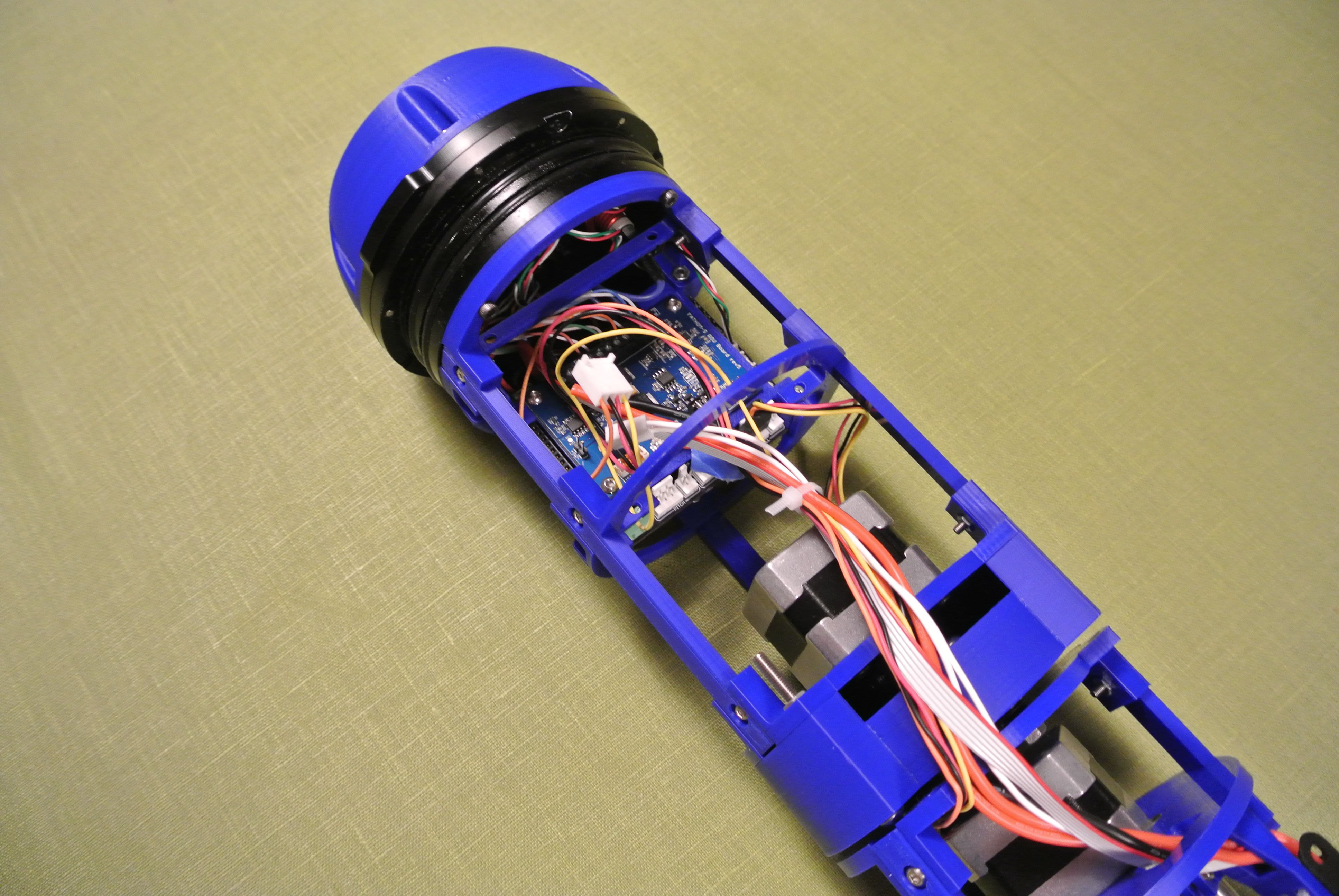
01/26/2018 at 06:16 • 0 commentsThe backend has been redesigned to be much more open for the new control board, and all the connectors are much more accessible. Also the control board has been lowered to allow for the integration of the Pixhawk 2.1 autopilot (the Cube took up too much vertical space previously). Most of the update to V3.1 has been completed but wiring still has to be completed.
![]()
The planetary gearbox has also been thickened to reduce play, but the latest version printed with too much of a bond between gears so I plan on reprinting this on a FORM 2 printer as this will be able to achieve a much better tolerance. I also changed the position of wiring past the planetary gearbox; previously the wiring ran on the side of the gearbox, which limited rotation, however the wiring now passes over the top of the gearbox and rotatory limits are symmetrical.
Nothing noteworthy has occurred to the mass assembly, apart from the general thickening of printed pieces.
![]()
The exterior components have been reprinted in 100% PLA and are not resin coated (The prints previously failed with 100% infill and let in water so had to be coated). However PLA still absorbed water – reports are a ~5% weight increase over a period of 30 days submerged, so I will look at printing the exterior components from PET-G.
-
Buoyancy engine update
01/26/2018 at 06:07 • 0 commentsThe last few weeks have been completely hectic and I have been unable to find time to document progress. I’m currently on a flight from London to Los Angeles to take up a residency at Supplygrame’s DesignLab to work on the glider, so I thought it would be a good time to do a few updates on the glider’s progress. I’ll split the update into two shorter sections, one for the buoyancy engine and another for the backend.
Throughout most of the upgrade from version 3 to 3.1 I have been thickening components to improve structural strength, notably in the buoyancy engine. Below are two images of the engine, before and after the upgrade.
![]()
![]()
Also note that the stepper motor has been upgraded from a NEMA 17 to a NEMA 23 motor, which runs at an equal power but has far greater torque. I have also moved the buoyancy engine stepper motor driver from the control board to mounted at the front of the glider, so that communication wires can be of a lower gauge and greater power can be delivered to the engine’s stepper motor. I have also upgraded the stepper motor from a A4988 to an AMIS-30543, as stated in my previous update. This allows for SPI communication to control the stepper motor more accurately and alter coil current on the fly.
![]()
All of the glider’s components in contact with water are rated to a depth of at least 100m, apart from the buoyancy engine. Therefore a depth rating of the glider can be determined by pressure testing the buoyancy engine (unless it can perform to a depth greater than 100m, which is almost guaranteed to be false). Hence I meant to test the buoyancy engine, however I was time constrained and air is a harder medium to deal with than I initially thought. Regardless, I’ll outline briefly the attempted testing method for anyone is interested.
![]()
The idea was to connect the engine to a water barrel using the same tubing and connectors that are within the glider, to try and accurately represent the system used. The barrel then had a pump attached (it was a car tyre pump until a lack of suitable power source became an issue) to pressurise the water within the container until the engine failed. The engine would constantly pump as I believed the syringe seals were more likely to fail when moving. Unfortunately the seal at the top of the container wasn’t sufficient and even after multiple layers of airtight tape there were small leaks that would reduce pressure within the container. I was going to switch to using a silicone sealant to properly air-tighten the container but I ran out of time.
-
Control board v0.3 designed and ordered
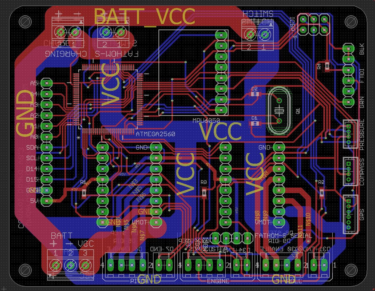
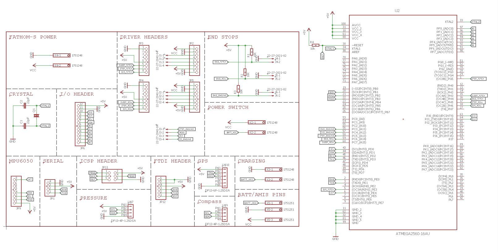
01/10/2018 at 19:34 • 0 commentsOver the last few days I've updated the design for the control board, with two notable improvements. The first is the hook-up of the "enable" pins of the stepper motor drivers to the ATMEGA2560, so that it is possible to power down the drivers whilst not in use in order to maximise battery life. The other main update is the removal of the A4988 for the buoyancy engine stepper motor, instead sending signals to an AMIS-30543 stepper motor driver board, which is mounted at the front of the glider next to the buoyancy engine. The AMIS-30543 has a greater current capability (3A vs 1.8A) and uses the SPI communication to control current, sleep, etc. I made sure that the new PCB could fit lower down in the 4" enclosure, in order to accommodate a full Pixhawk 2.1 (the vertical height of the "Cube" meant that it previously wouldn't fit).
![]()
![]()
The PCBs are being manufactured by OSHpark and I should have some assembled boards by mid next week. As usual, all design files are in the development DropBox folder, in the Underwater_glider/glider_pcbs/Control_board/v0.3 directory.
Over the coming days I will be testing the buoyancy engine to potentially determine a working depth limit.
-
General update
12/02/2017 at 18:28 • 0 commentsThe last few weeks have been completely hectic with the Hackaday prize and sorting out university, things are only just starting to settle. It was really great to go over to the US for the Supercon, I enjoyed meeting everyone and I appreciate all the useful feedback I recieved. As part of winning the Hackaday prize, I hope to take up the residency at Supplyframe's DesignLab in the New Year and this will give me a three month period to focus solely on the glider.
Over the coming weeks I'll be updating the design of the glider from v3 to v3.1, a version of the glider that I believe will be suitable for alpha kits for real world testing. During the glider update I will be testing various parts of the glider to ensure reliability and to get some performance figures.
The main testing will be on the buoyancy engine, so I have a depth rating and an understanding as to how well it performs. As the glider/buoyancy engine is quite large it will be hopefully be done in a modified water tank with a car pump attached. A camera on the inside of the tank will be used to monitor the state of the buoyancy engine to make sure there are no leaks, etc.
For those interested in kits, I appreciate the support and I am aiming at finalising the design so that I can come up with a finalised cost. I looked at printing the parts using 3D printing services but it is more effective print the parts myself, so I have purchased a CR-10 printer for printing sets of parts.
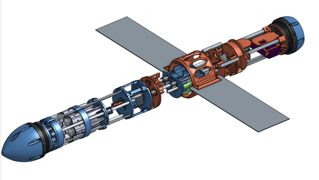
You can view the live development CAD of v3.1 here. Red is v3 parts and the blue parts are parts that have been updated to v3.1
![]()
-
Future testing and to-do list
10/18/2017 at 17:18 • 0 commentsAs the third generation of hardware is completed for the glider, it has reached a stage where it needs to undergo testing to find the capabilities of the glider. Below are a few tests that need to be performed on the glider and a brief explanation of each test:
- Testing of the buoyancy engine system to determine a depth rating of the glider - All of the exterior components of the glider (end-caps, switches, underwater plug etc) are rated to at least a 100m depth, whereas the buoyancy engine does not currently have a rating. A pressure test of the buoyancy engine (likely destructive) will determine the overall depth rating of the glider. (The test would be to attach all the syringes to another set of syringes with a plate on top, weight would be added to the plate until the stepper motor cannot move the weight or the seals break, if the former, the stepper motor will be upgraded.)
- Perform reliability testing of the buoyancy engine under pressure to make sure that the movement systems do not become stiff. Minimum of 24 hours.
- Perform underwater tests with the glider running at different glide angles, used to determine the best angle of attack for different missions (steeper = faster, shallower = greater endurance)
- Perform extended endurance/range testing as the current endurance/range of the glider is calculated by extrapolating out current data (42 hour running battery life at ~0.2m/s = 28km). Once a depth rating of the glider is achieved, the glider can glide to a greater depth which will mean that it reaches a greater speed and spends less of its time transitioning between gliding states, so the range of the glider will increase.
- As I have only been able to test the glider in small areas of water, it has not been possible as of yet to demonstrate the turning of the glider clearly, so the glider needs to be tested in a larger body of water.
I have also put together a to-do list to get the glider to version 3.1. This list is primarily hardware and does not include any to-do points concerning the Pixhawk and automated waypoint navigation system. An up-to-date version of this to-do list will be kept in the dropbox folder.
Printed components
- Change acme nut to an anti-backlash nut to prevent acme screw wear in the long term
- Redesign wing mounts to have a slight dihedral so that the glider is more stable underwater
- Choose a standardised micro lever switch and use screws as opposed to hot glue
- Make the planetary gearbox thicker to reduce play/wear
- Redesign the wiring routes past the planetary gearbox
- Redesign the Pixhawk mounting plate so that the board can be more easily placed/removed
- Try and fit all of the external ballast bars internally, to reduce drag etc
- Change all roll components to a diameter of 98mm, as opposed to 100mm (to reduce friction inside the tubing)
- Strengthen endcap mounts to prevent bowing
- Strengthen engine bearing fastener to prevent bowing
- Redesign motor/acme clamps to increase strength
- Upgrade buoyancy engine motor to a NEMA 23 motor if required
- Make pogo PCB mounting plates thicker to prevent bowing
PCB
- Hookup the “enable” pins of the A4988 boards, so that you can power off the stepper motors when they’re not in use to increase battery life
- Hookup a greater number of the unused I/O pins to header pins to increase the number of additional sensors, etc. that can be used
- Reposition the A4988 stepper motor drivers so that you can access all of the potentiometers without drilling into the aluminium tubing
- Use the Blue Robotics switch as switch to a relay for the main power control - the switch is potentially getting to the edge of its current capability
General
- Think of an alternative to aluminium tubing, to reduce variability in reproduction
- Upgrade the hotend of the printer and print all components in polycarbonate
- Apply for Sparkfun funding for their dissolved oxygen sensor
- Contact Onshape on their forums with review/feedback - global parameters or feature folders are the main suggestions
- Look at using industrial pogo connector or using a plug/receptacle and signal converter
- Look at moving the motor driver for the buoyancy engine motor towards the front (in front of pogo connector) to reduce the number of wires through the cable chain
-
Build instructions and possible kits
10/15/2017 at 09:27 • 13 commentsFull instructions for the glider are now completed, with a level of detail that if you're able to assemble a RepRap kit, you should be able to assemble the glider. The only tools required are a 3D printer, soldering station, dremel and then various handtools such as hacksaw/allen keys etc.
With the Onshape CAD model, you are able to duplicate the model and adapt the hardware for your own requirements (such as adding a front mounted camera) - this glider is designed to be a hardware platform for others to use/adapt, not a project with a fixed use case.
If there is interest, I may look into the possibility of putting together a few kits containing all parts/3D printed components that are known to work together so you can assemble the whole glider in a couple of weekends.
-
Assembled CAD model (and onshape features)
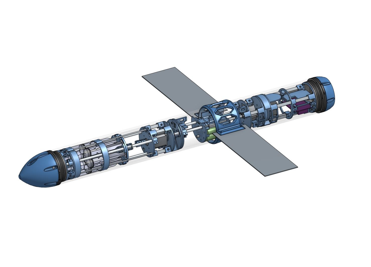
10/10/2017 at 10:45 • 0 comments![]()
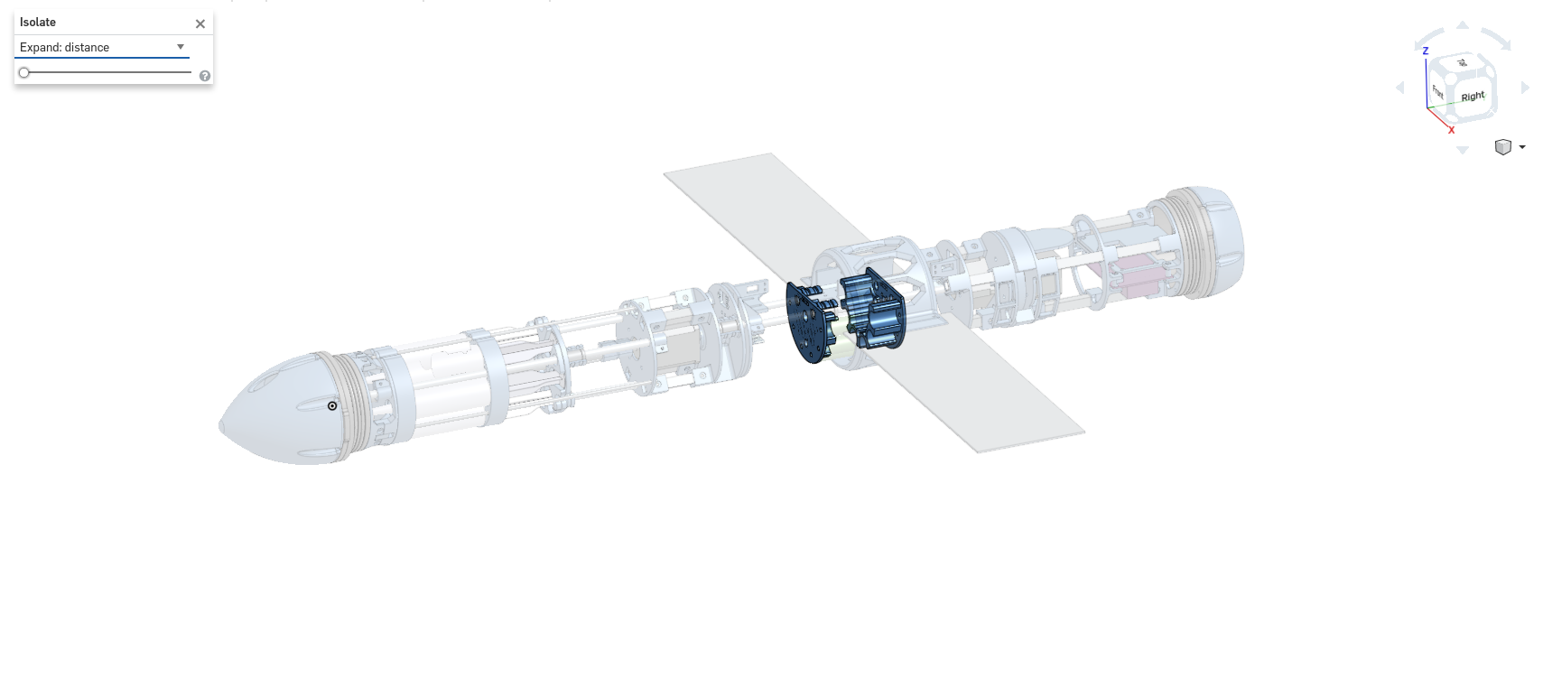
I've finished assembling the Onshape CAD model for the third generation of the glider. It can be viewed here. There are a couple of features of Onshape that make visulisation of the model/sub-systems easier. You can hide objects which completely removes them from view (Useful for the tubing as it then allows you to select internal components). You can also isolate a component (or multiple) which makes all other components faded and makes it very clear as to what the individual components look like etc.
![]()
-
Final(ish) third generation hardware
10/07/2017 at 16:13 • 0 comments![]()
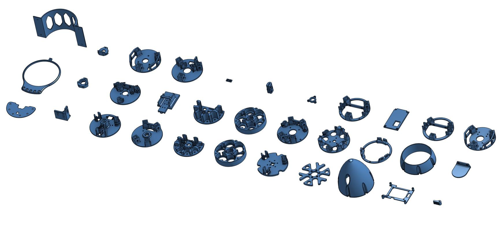
I have gone over the glider CAD model and I have changed the parts so that no post processing is required (unless I've missed something).
Within the Onshape model, the test prints should be printed first and they are used to select values for the component variables.
![]()
I am aware there is currently a lack of instructions for the third generation of hardware but all the images of the assembly can be found in the dropbox folder.
I should update the project page soon with full instructions for the assembly of the glider.
-
Ascending and descending underwater
09/22/2017 at 21:54 • 0 commentsJust a quick update regarding some testing of the new hardware: I recently had access to a pool and I was able to test the glider's new hardware in deeper water. There is currently no control software onboard, so the glider is dead reckoning using set timer delays (4 seconds down, 4 seconds up). The pitch mass is not varied during the duration of the filming. The angle of attack is currently quite steep, but this will be optimised as a PID algorithm becomes integrated. The tether at the back of the glider is only there for remote programming, which made it quicker to modify timings whilst the glider was in the water; the tether did not need to be attached whilst it was performing this gliding sequence.
OSUG: Open-Source Underwater Glider
A versatile autonomous environmental drone using a buoyancy engine