MasterOfNull
-
Genesis
02/14/2018 at 21:58 • 0 commentsExactly one month ago this idea was born on the OpenPnP forum.
It's not often I can trace the origin of something I've built to more than a vague recollection of events, but not this one.
This idea was born Jan 14th at 12:48pm when it was suggested in reply to my original post by the aptly named TheCunningFellow. So this is a shout out to him and the folks over at the OpenPnP forum for their help and support fielding my vague and often uneducated questions over the last month.
Thank you.
-
Mirrors mounted, and my endoscope sucks.
02/14/2018 at 07:40 • 0 commentsI mounted the camera and the mirrors today.
It took about 10x longer than it should have and I found out that my $9 endoscope was that price for a reason.
I toiled for many hours trying to align the mirrors. The image was always off center no matter how I adjusted them. There is about 5 degrees of adjustment built into the mounts before you set the optics, and that just wasn't enough. I was starting to doubt my optics model...
Finally I removed the camera and just sighted down the bore without it. It looked perfect...
I put the camera in a V block and aligned it to some graph paper. It was permanently aimed down and to the left. The centerline of the video was about 10 degrees off from the centerline of the case.
So I opened up the endoscope, cut off the epoxy seating the sensor to the control board, and re-aligned it manually. A couple drops of UV cure adhesive stuck i in place. I reassembled it to check it was now straight, took it back apart adding a puddle of UV cure, and assembled it again.
The imaging sensor of the endoscope must not be properly centered on the lens as when the centerline of the image is aligned to the case, the angle of the sensor itself is pretty far off from where it should be. So I'm likely getting some parallaxing and variable focus for my video, but there isn't really anything I can do about that. It's still good enough to move on for now.
So here it is..
The world premiere video..
Of a mirror flipping..
The dust looks a lot worse than it normally does here from the steep angle of my lighting. It was hard to get both areas lit up relatively evenly.
-
Mirror, mirror..
02/13/2018 at 22:04 • 0 commentsDecided to try again with the mirrors.
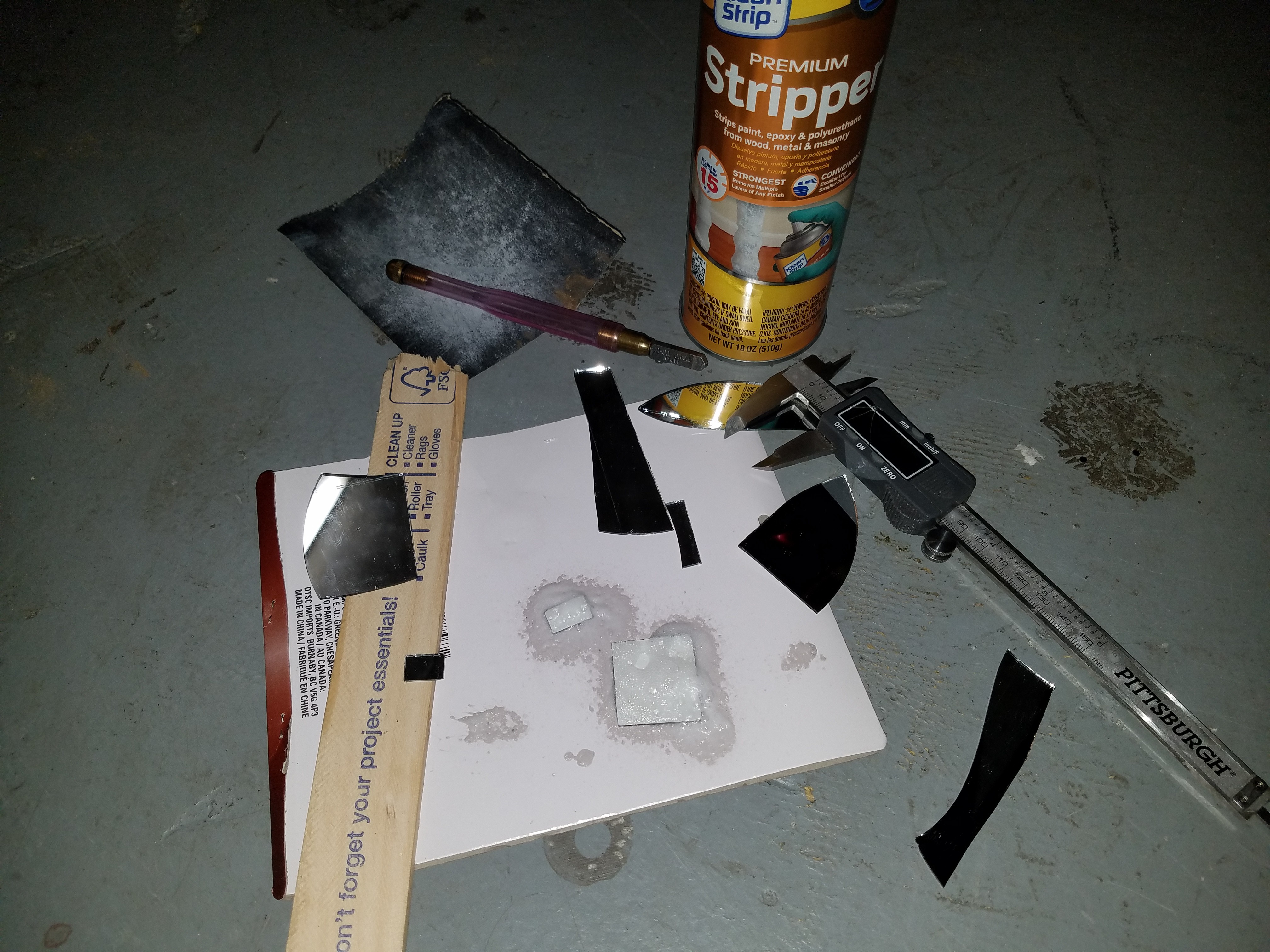
This time I cut them to size first, and then used actual paint stripper to remove the back coating. The results were fantastic.
First cut them to size and sand the edges with silicon carbide sandpaper.
Then wash them in soap and water.
Then give them a generous coat of paint stripper in a clean environment (unlike mine).
I got lucky. I realized as I was wiping them down after stripping that the little flakes of glass I had created from cutting/sanding the edges could easily ruin the silver.
![]()
It took two coats of paint stripper, and a gentle wipe with some paper towel after each, over the course of 30 minutes.
The stripper left a residue on the silver which was easily removed with some alcohol.
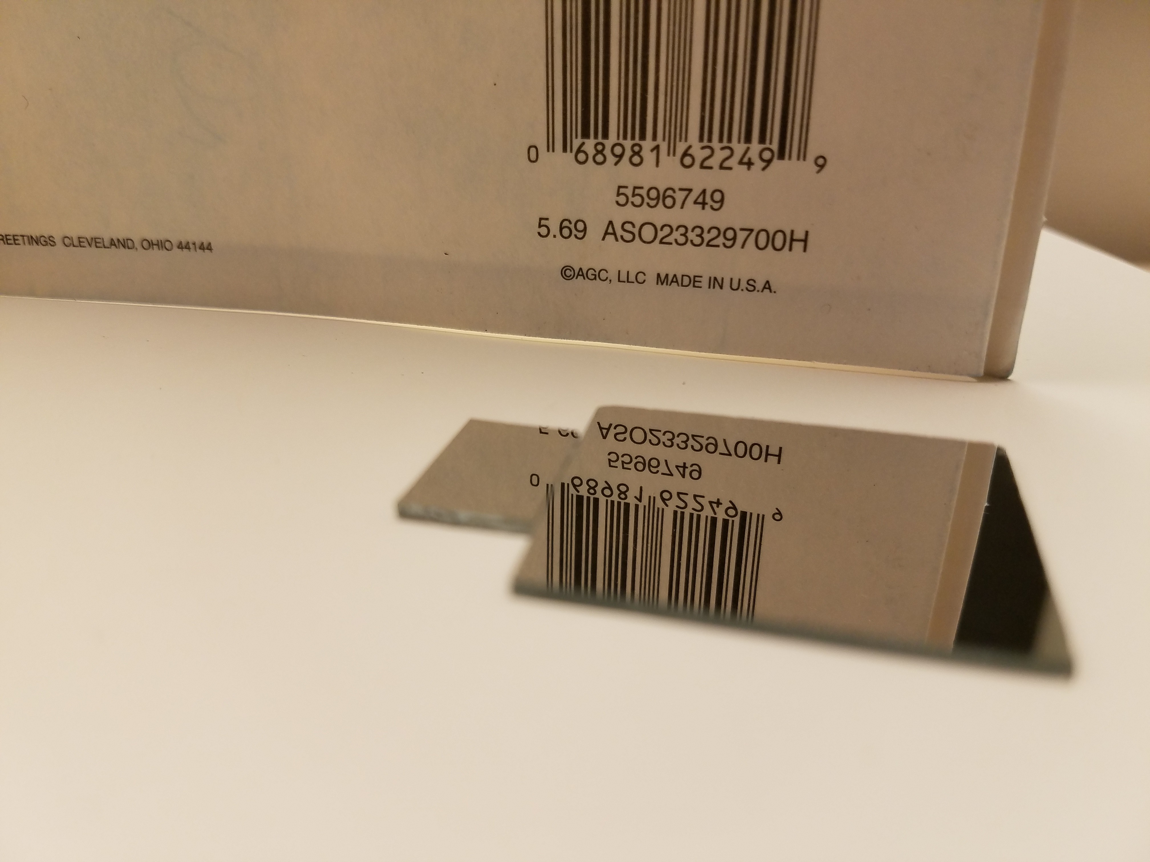
The reveal:
![]()
Holding them up to a bright light, I did a whole lot better this time. No scratches/holes in the silver from me rubbing too hard like last time.
Now to install them in the arm.
-
Mirror arm done.
02/13/2018 at 01:09 • 0 commentsCompleted the mirror arm to match my calculated optical path. 3 grams, without the mirrors and it prints flat with no supports. In openSCAD, hull() is your friend.
Minus the original mind bending problem of modeling the optical measurements from extended and having to design/print this flat, hull() actually makes complicated shapes like this relatively painless. I eventually figured out I could just rotate the optics model. Duh..
![]()
The flat bits extending from the cylinders mate with matching flats on the head giving it a positive stop for positioning. I originally added screws here for adjustment, but I didn't like how that turned out and deleted them. The stops are not clearanced so I can shave them down a bit to fine tune the stop angle.
I printed it out and the slot for the larger mirror I made was too thin. The slot angle is critical and grabbing a pretty small area on the mirror, so I can't really trim the plastic it to fit and expect good results.
I corrected the slot size in the model. Printing another.
-
Helping out Cura.
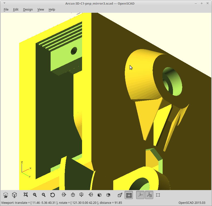
02/12/2018 at 05:10 • 0 commentsCura doesn't handle bridging very well. If a bridged area is wider than you set your wall thickness to, it is more than happy to start printing in thin air.
However, you can still force it to get a clue with some tweaks to your model.
Cut the bottom of a bridged area into smaller long segments and make the segment width a multiple of your nozzle size. It will then do the right thing.
This is visible here as the ribbed area in the servo pocket.
![]()
The cuts only need to be about 3 layers deep for this to work.
Similarly if you have a large flat section which doesn't attach on both ends, make it.
-
More tweaks.
02/11/2018 at 22:25 • 0 commentsThe mirror servo was really close to the limit switch. I moved it down and in.
Adjusted some things for better results with the required bridges.
Also reduced the size of the bearing cutouts by a tiny bit to get a press fit.
![]()
Weight is now down to 17 grams.
Printing again.
-
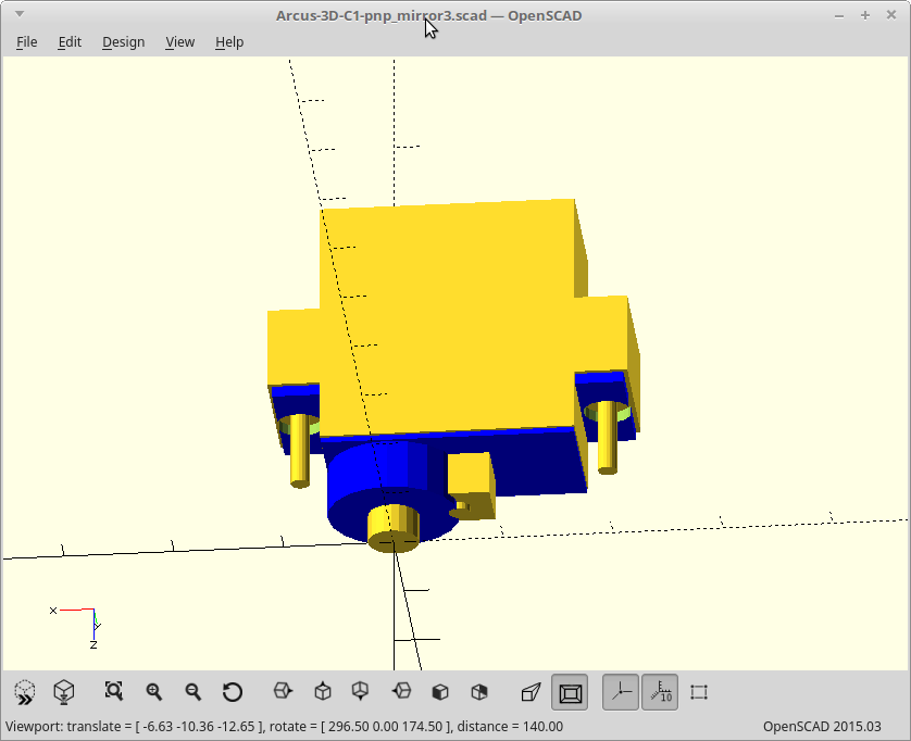
Suspect servo statistics subvert successful spline syncronization
02/11/2018 at 00:36 • 0 commentsEverything fit, but my gears for nozzle rotation didn't mesh properly.
To line things up and make the cutouts for where the servos were going to sit I had two different models. One was the actual servo model, and one was the negative I used to generate the pocket it would need. The negative one was a little oversized with exaggerated depth for the flanges and pegs to generate the screw holes. It worked well.
Well it seems over the course of the project I accidentally modified the cutout version and changed the depth from the output shaft to the mounting flanges. I've flipped the side of the flange I was going to use a couple times so I can understand how it happened..
Blue is the original, yellow is my cutout.
![]()
Depth is kinda important for a right angle drive, so now the gears don't mesh. Fixing.
-
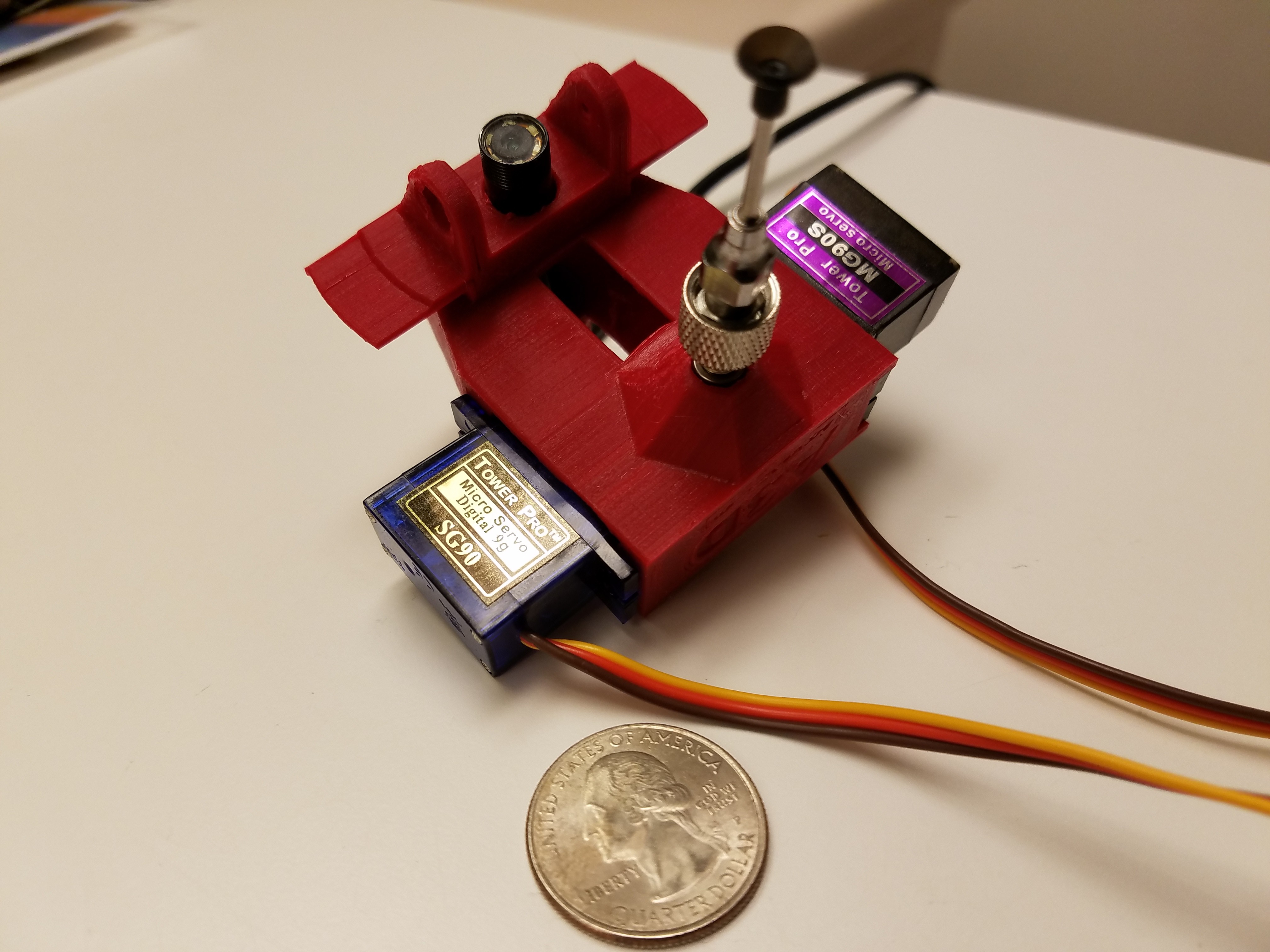
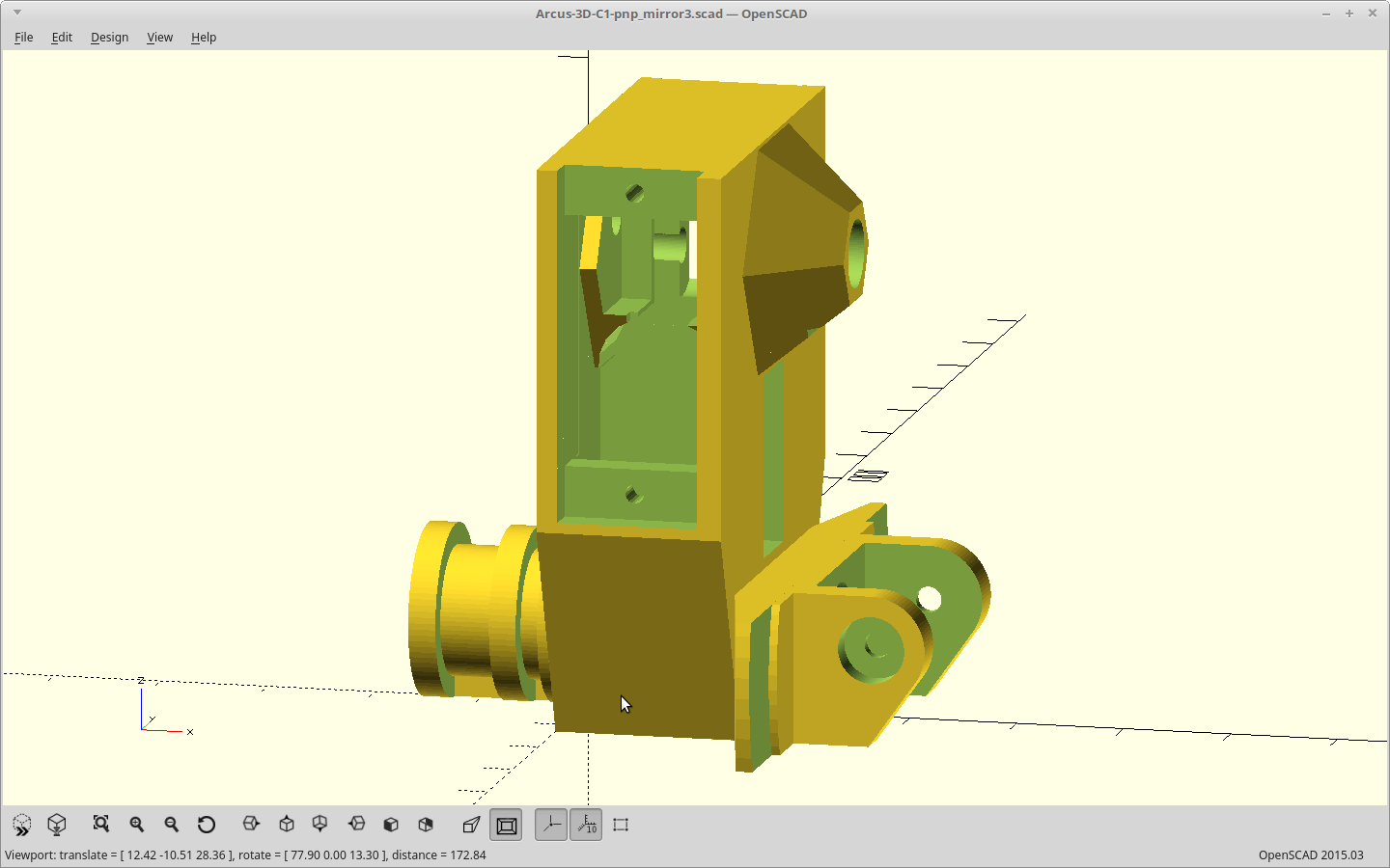
First look.
02/10/2018 at 09:54 • 0 commentsAssembled for the first time. Everything fits.
![]()
Servo on the left has a 2:1 right angle drive for rotation, and the one on the right is there to drive the mirror retraction.
The blue servo is a genuine Tower Pro servo. The genuine servo is significantly more accurate than the grey knockoff one on the right. About 5x more accurate. That right there almost killed this project before it started as doubling the rotation range means halving the accuracy. With the grey one that accuracy would have been about 7-10 degrees.
I may still ditch the lock part of the luer lock. On some of my nozzles it requires >360 degrees of rotation to engage which is kinda a problem as I only have 360 degrees of rotation available here.
Now to build the mirror arm..
-
Test print, printing..
02/10/2018 at 03:16 • 0 commentsI have a boat load of this red PLA, so doing a fast print in it just to check the fit of everything before I commit it to nylon.
I can see already that some areas are way, way thicker than they need to be. When I generated the model, I subtracted an inner hull from the outer hull but apparently my offset was really excessive and I didn't bother to look at the cross sectional view before I started the print.
I was wondering why Cura was calculating 24g for printed weight. Now I know.
EDIT: I edited the model thinning out the solid blocks of plastic I had in some areas. It's now 20g and that's probably where I'll leave it as the remaining solid areas, like the groove mount and PnP nozzle area, really should be solid.
I was also going too fast for my cooling, and over-extruding a bit too much so it was getting messy on the overhangs. I stopped the print. It's been a while since I've printed in PLA. :)
I did get two of the measurements I needed though and tweaked those. Printing again.
-
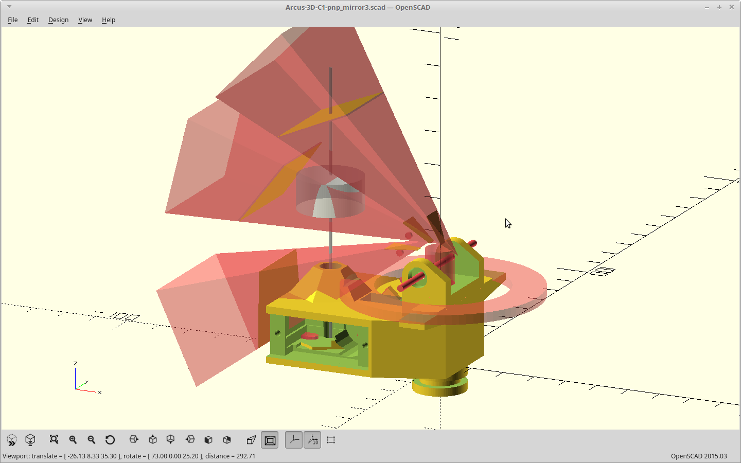
Looking good..
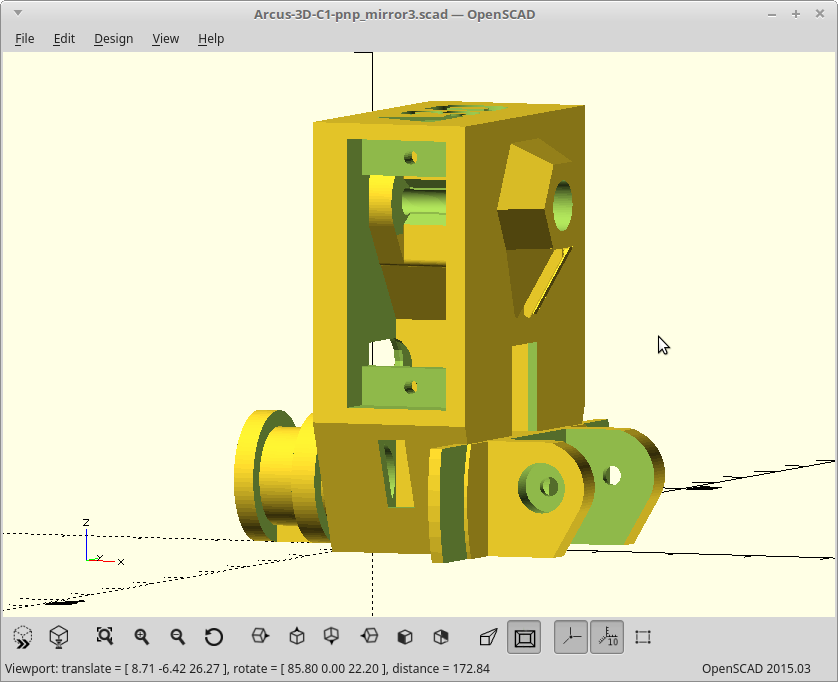
02/09/2018 at 20:03 • 0 commentsChanged my optical representation from a cone to 4:3 to match the camera and this yielded some better dimensions I could work with.
![]()
The path for the swingarm works, but I have not generated the actual part yet.
Did a little more cleanup, and it's finally ready to print.
![]()
It's only 55mm tall, but there are some bridges required which means I should probably take it easy on the print speed. I also have to dry out my nylon filament first as it's been a while since it's been used.
Arcus-3D-P1 - Pick and Place for 3D printers
Open source, mostly 3D printable, lightweight pick and place head for a standard groove mount