Introduction / Motivation
My experience with the ESP modules started with the ESP-01 module. First only with the simple AT-Commands over the serial interface. Later, when it was available, I started to use the Arduino IDE for ESP8266. For the ESP-01 I had developed an small #ESP-01 Breakout Board.
The board was on homebrew PCB and only uses the ESP-01. So the PCB and soldering was not good nor professional looking this way, but it works. But the IOs of the ESP-01 were quite limited. So I came up to design I new PCB for the "bigger" modules (they use all the same chip).
Some advantages of the modules with a custom PCB :
- easy and ready to use
- as simple as an Arduino, but:
- faster CPU
- wifi!
- more memory - not much more expensive
Features
(I only writing here about the newer rev2 - rev1 was similar but in some aspects different. It has also fewer features)
Based on my experiments with my ESP-01 breakout board this board has the following features:
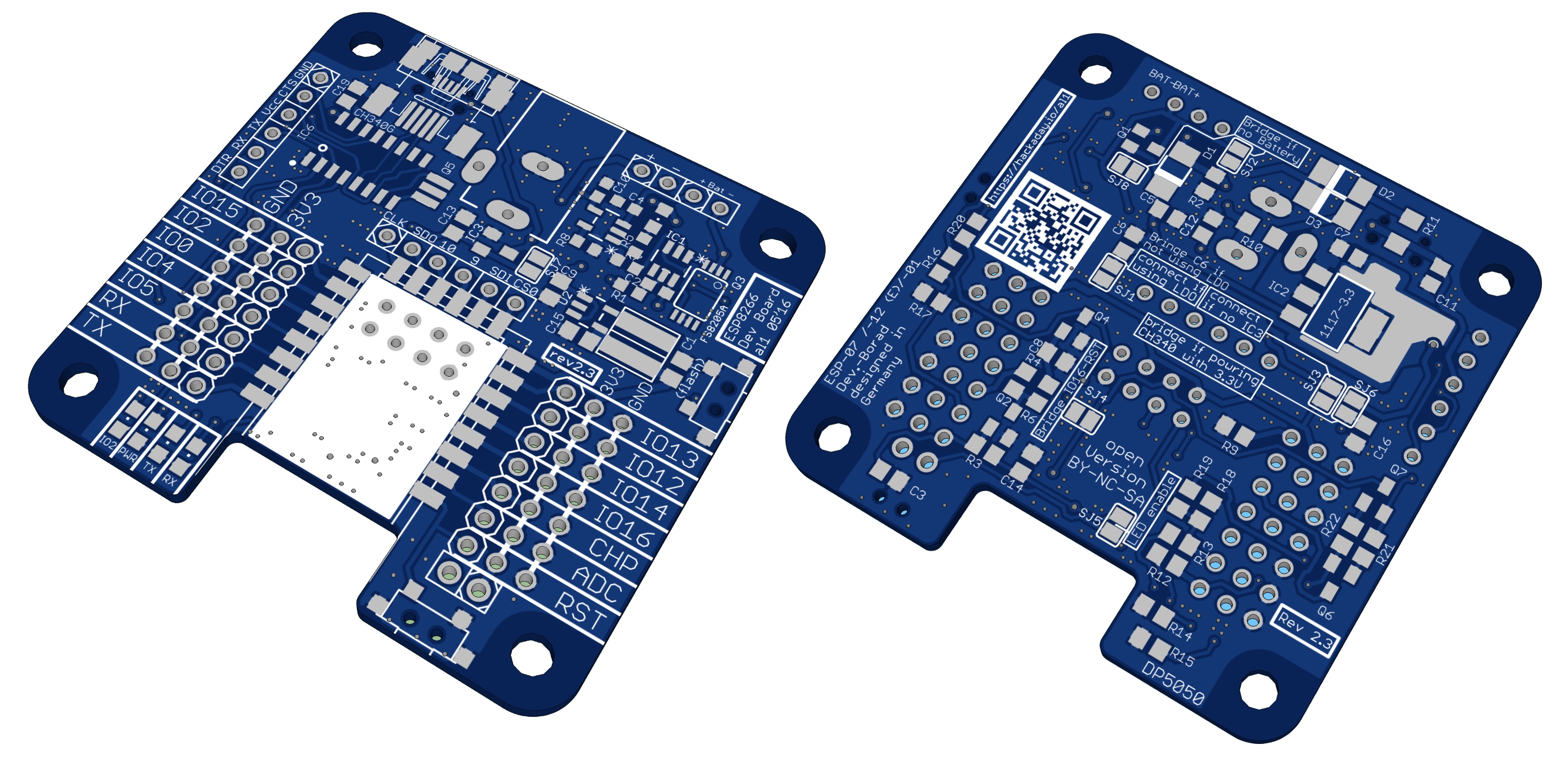
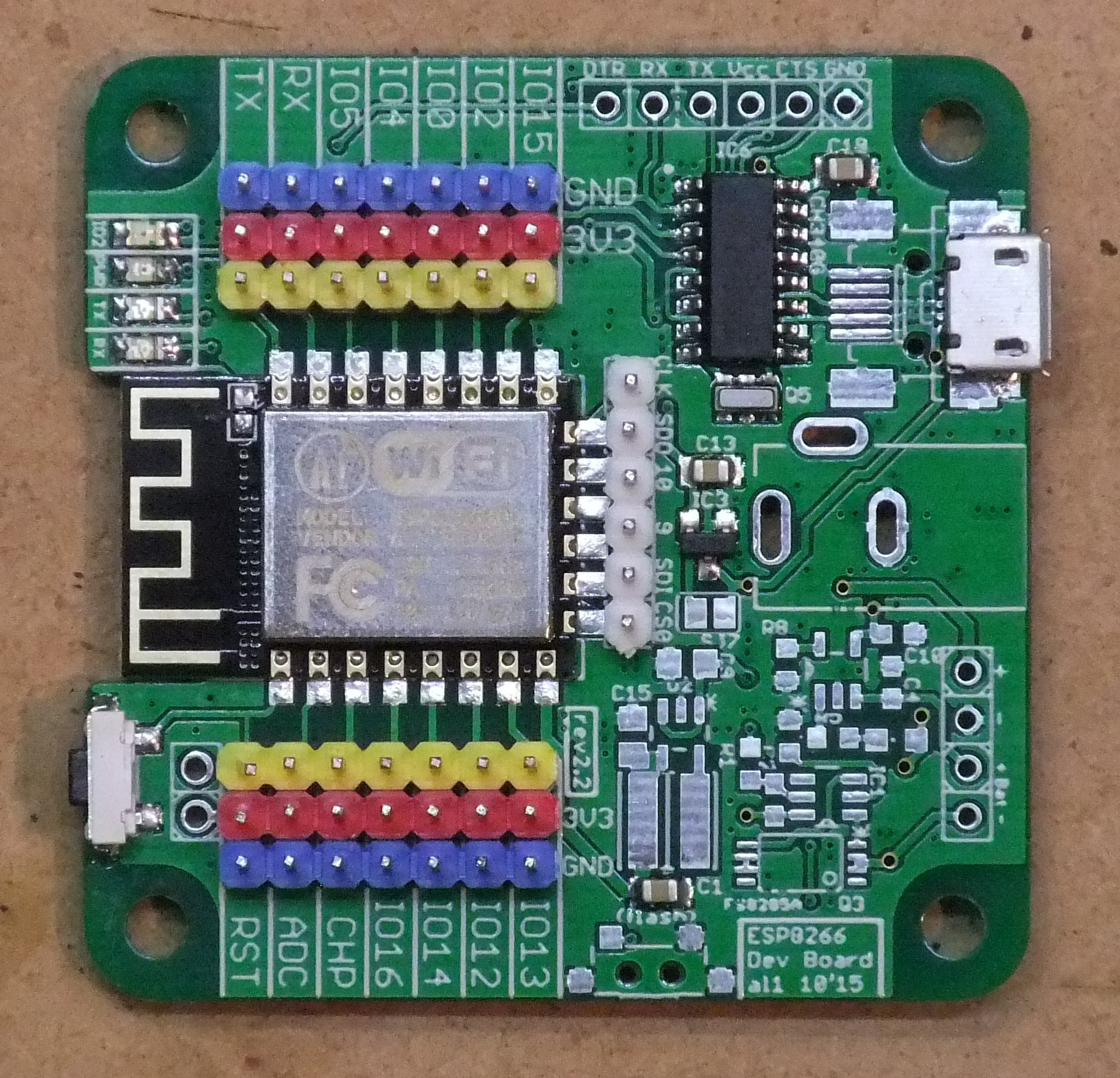
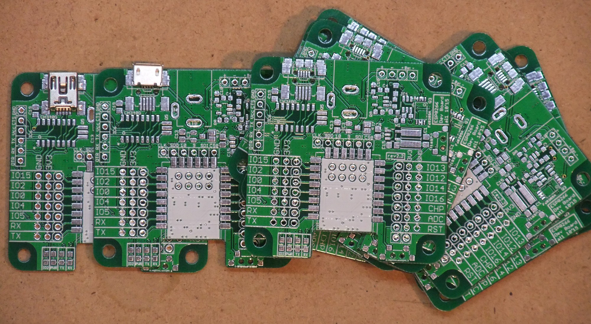
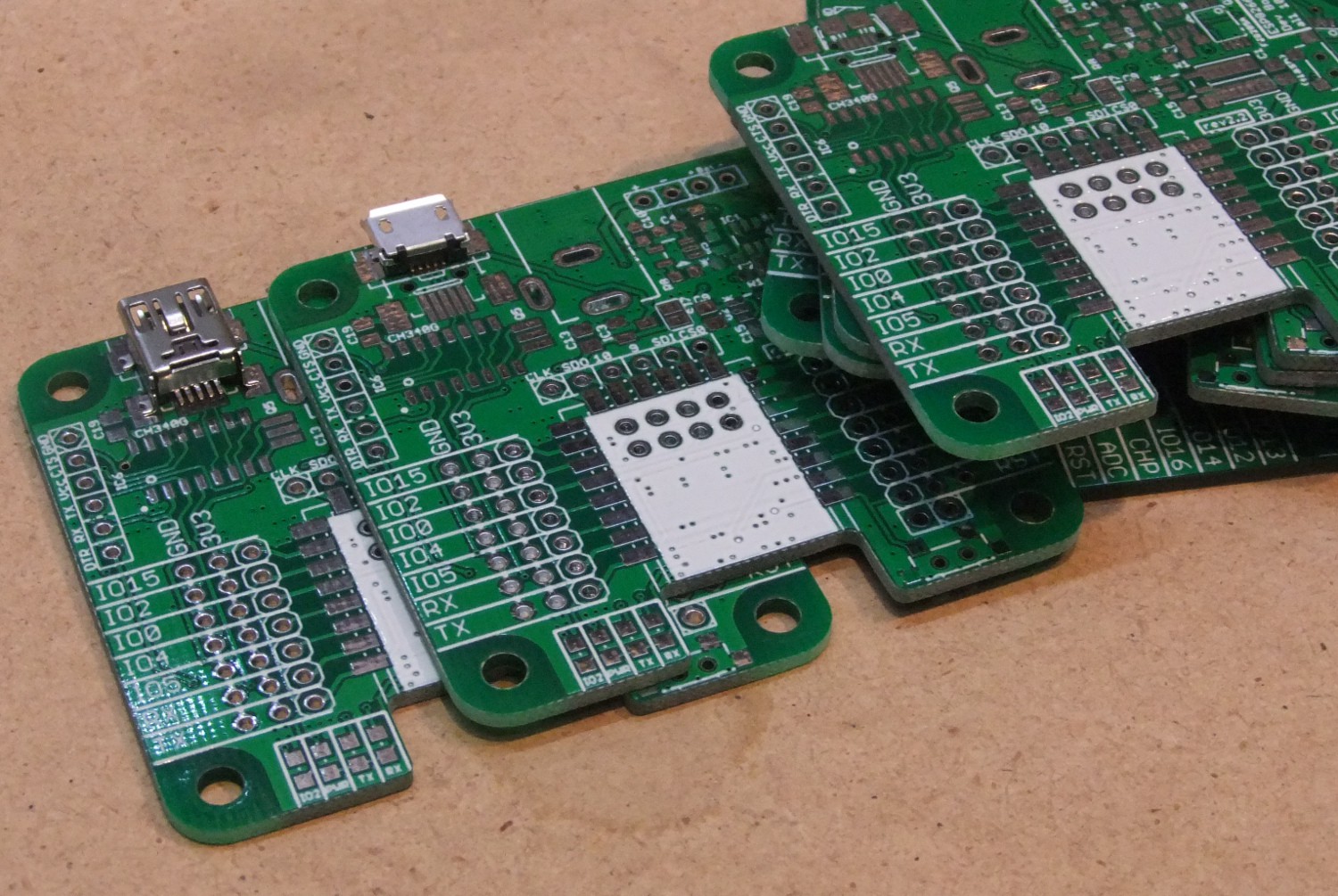
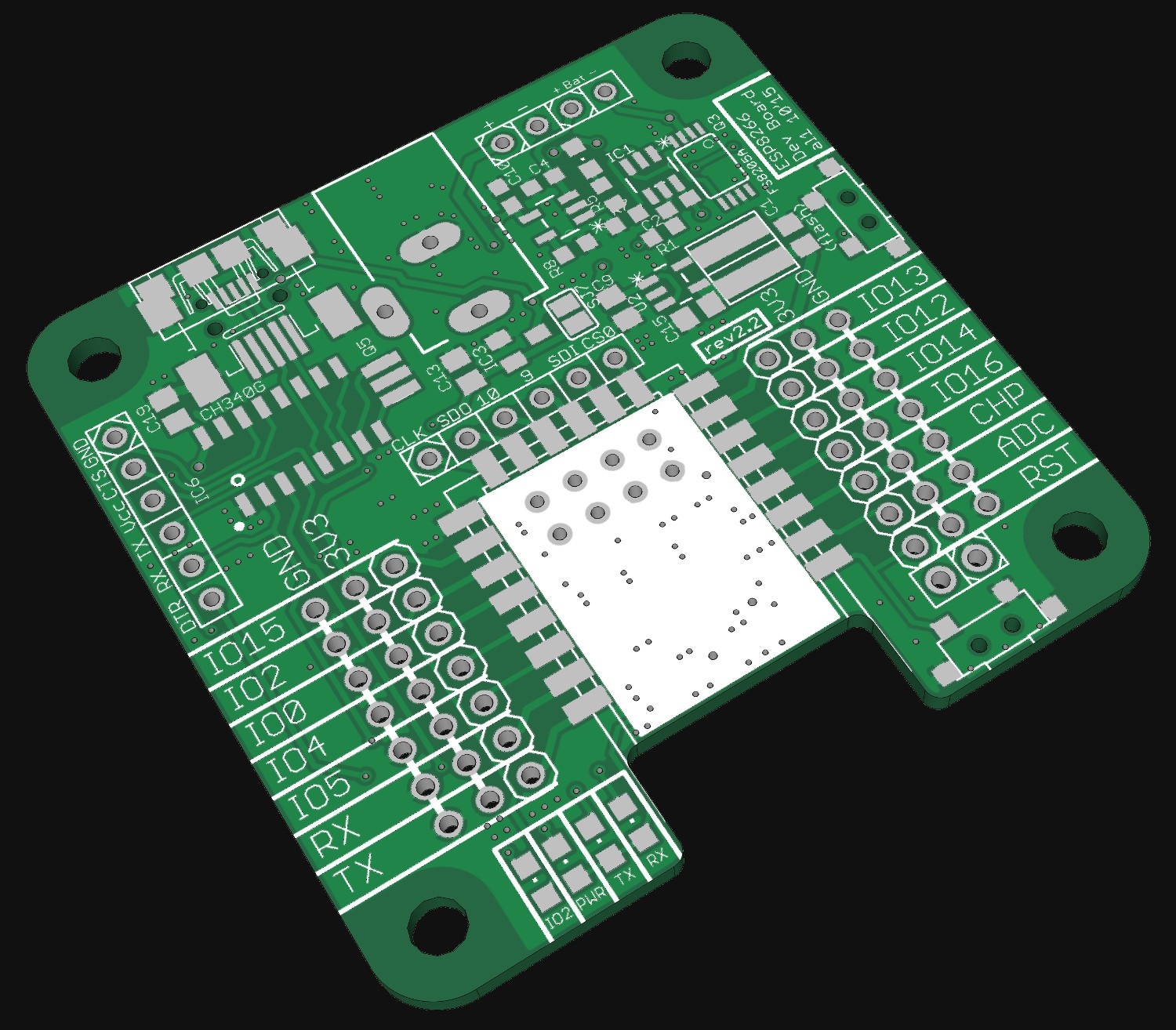
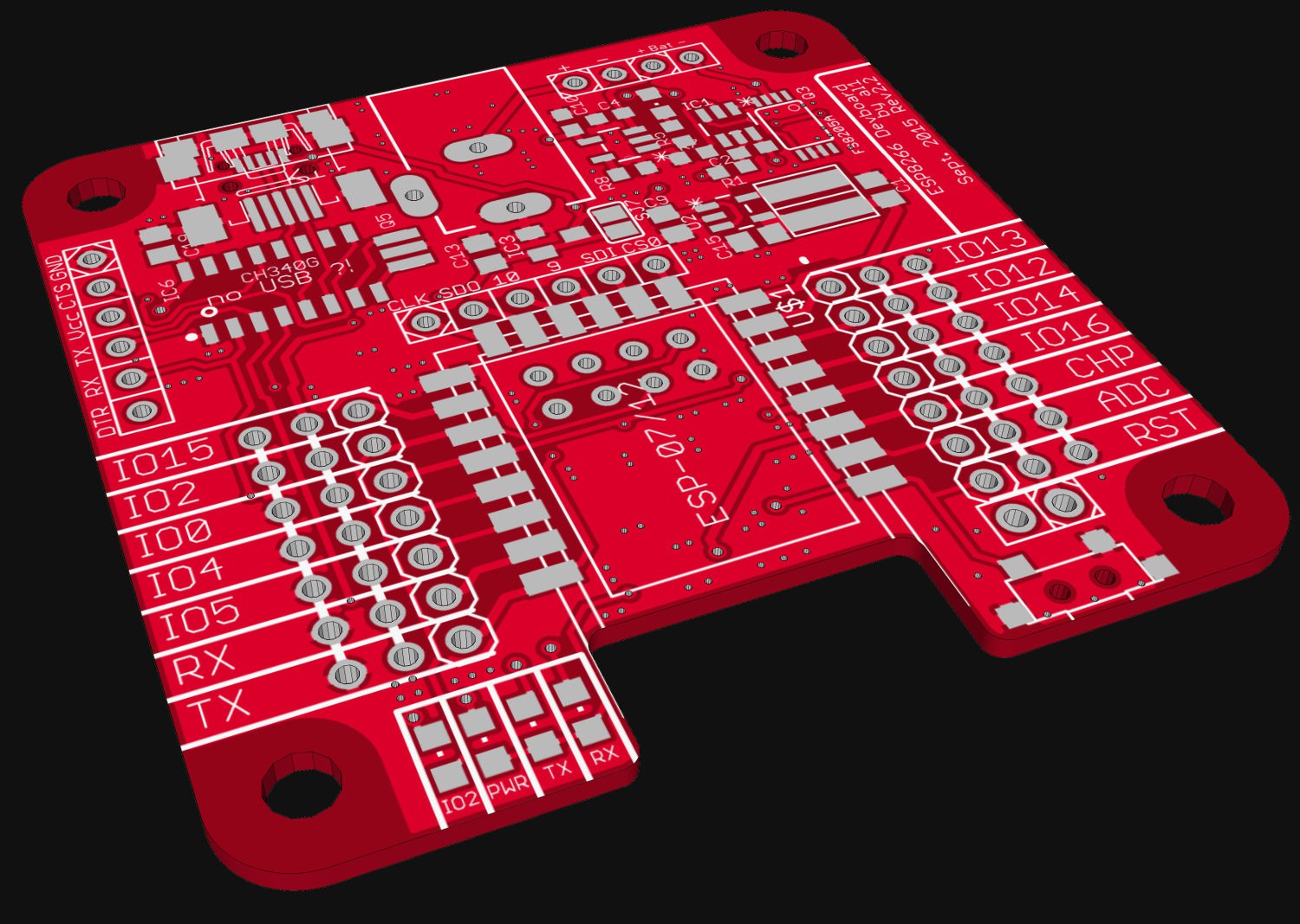
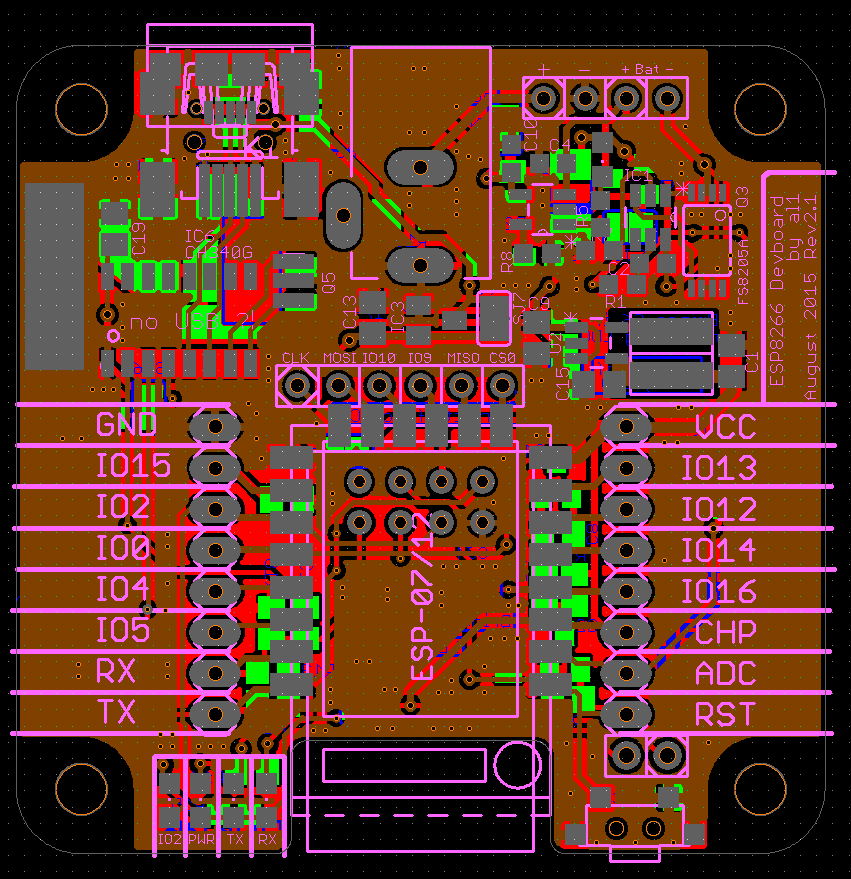
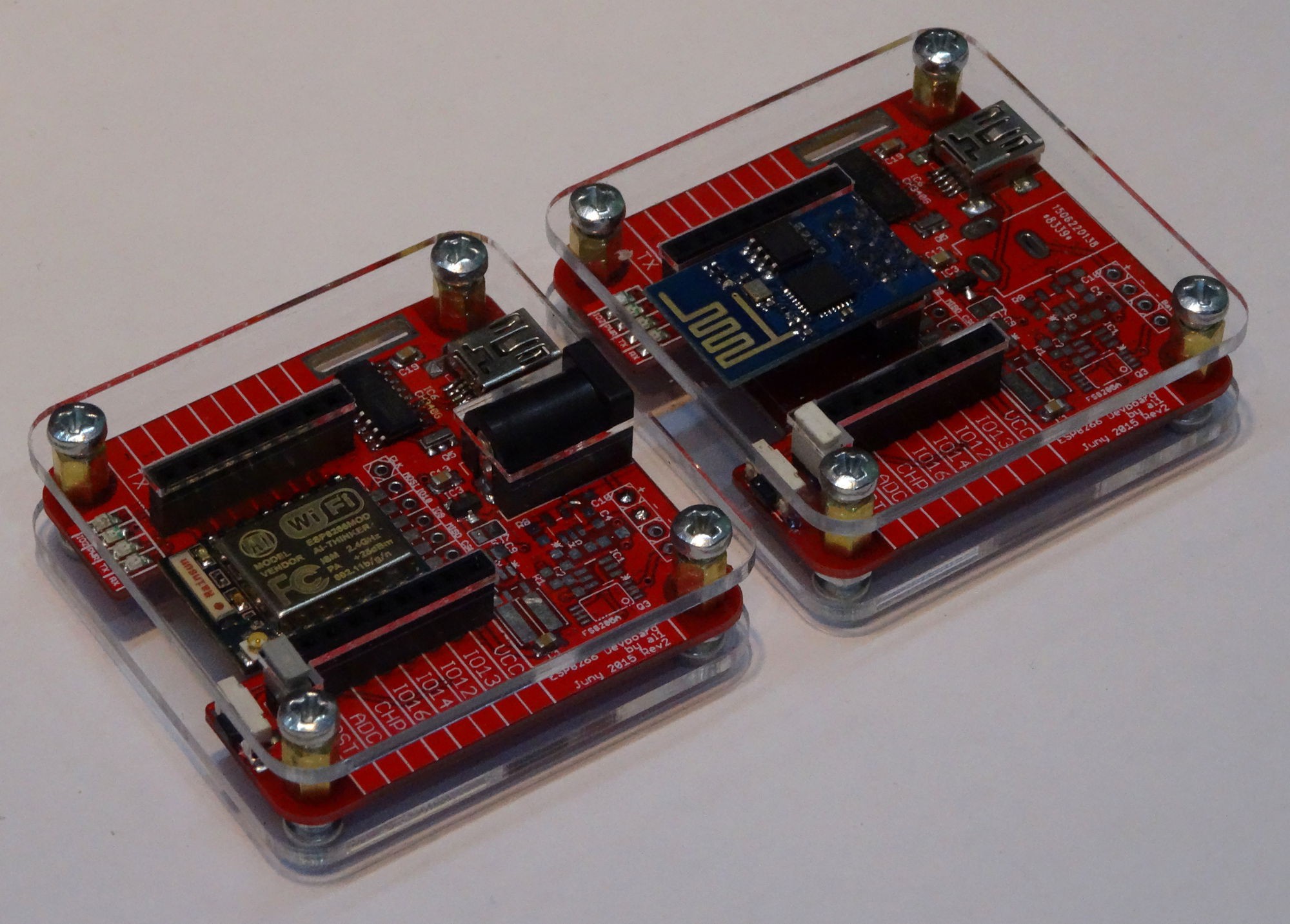
- Pads for ESP-12 , ESP12E, ESP-07 and ESP-01 Modules
- on Board power supply from:
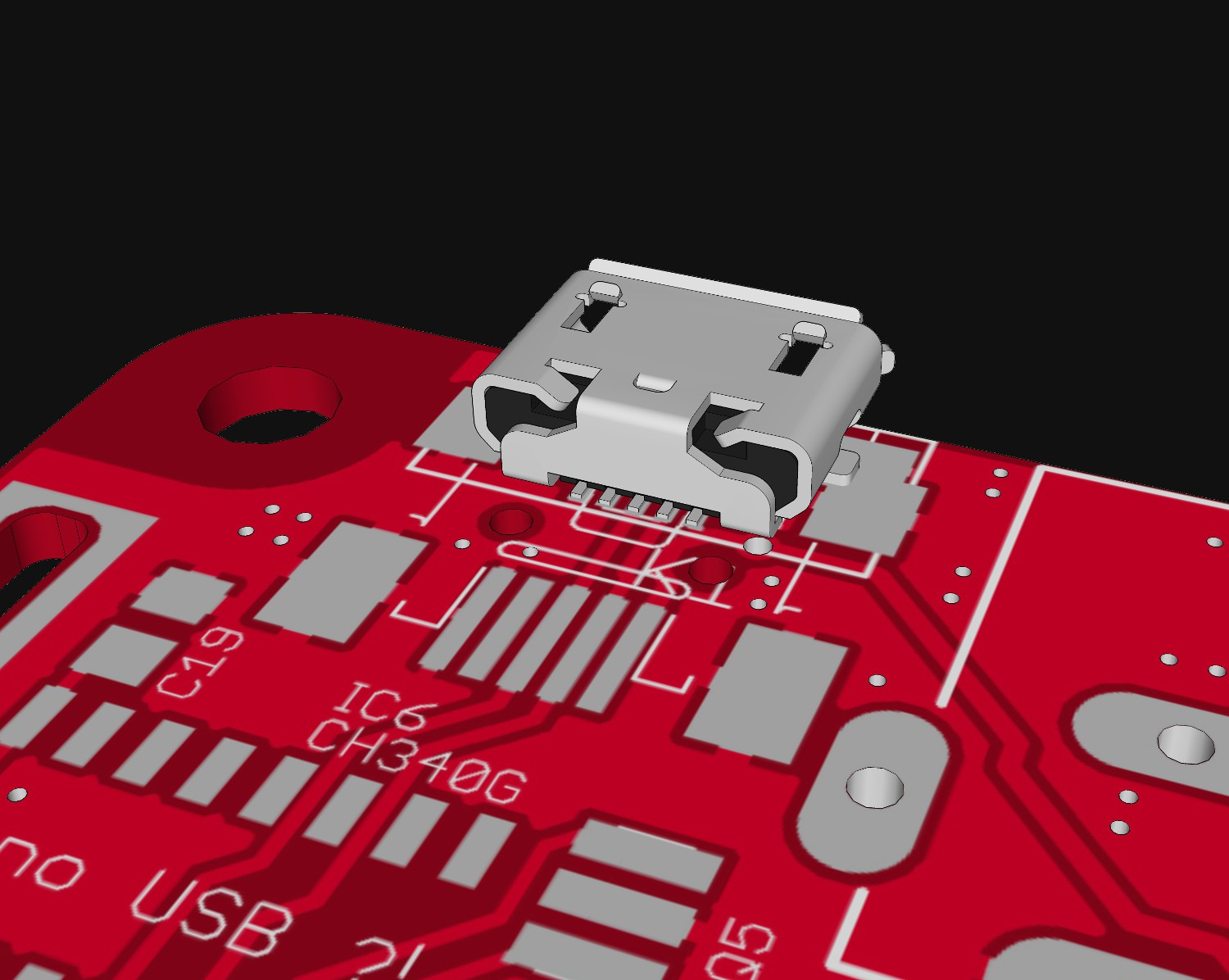
- USB (MINI)
- external power source (2,1mm power jack and 2,54 mm pin header)
- lipo battery (for off-grid operation)
- on board programming via USB to serial converter
- Headers for IOs
- rest / programming switch
- User LEDs: RX, TX, Power and GPIO2 LEdis available on the board
RX, TX, and Power LEDs kan be en/disabled via a Jumper to save power - Jumper to connect IO16 and reset (need for deepsleep?!)
New with rev 2.2
- optional compatibility to the NodeMCU boards
- mini OR micro USB
- polarity of power jack changed. now the centre pin is positive
- nice three row pin headers for direct servo connection
- now also FTDI-pinheader possible to connect external USB-Sertial board
Power supply
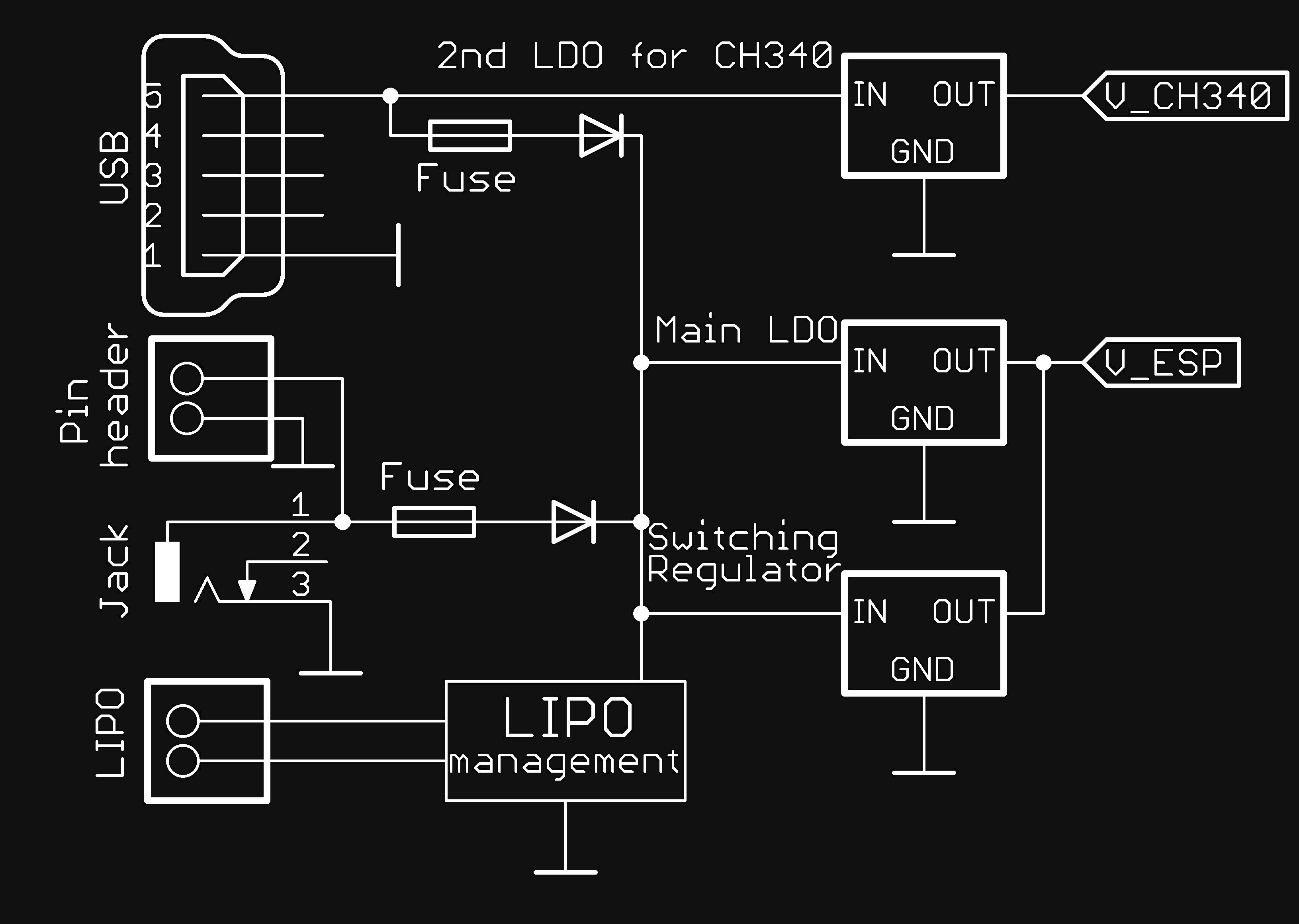
I wanted to make a very flexible power supply. Beside there different power sources, you can assemble two different regulator settings. As power source the USB-Power, an external DC-Voltage or a lipo battery can be used.
When connecting the Device via USB to a PC USB-Power can be used. You can also connect normal power to the Device via the USB connector.
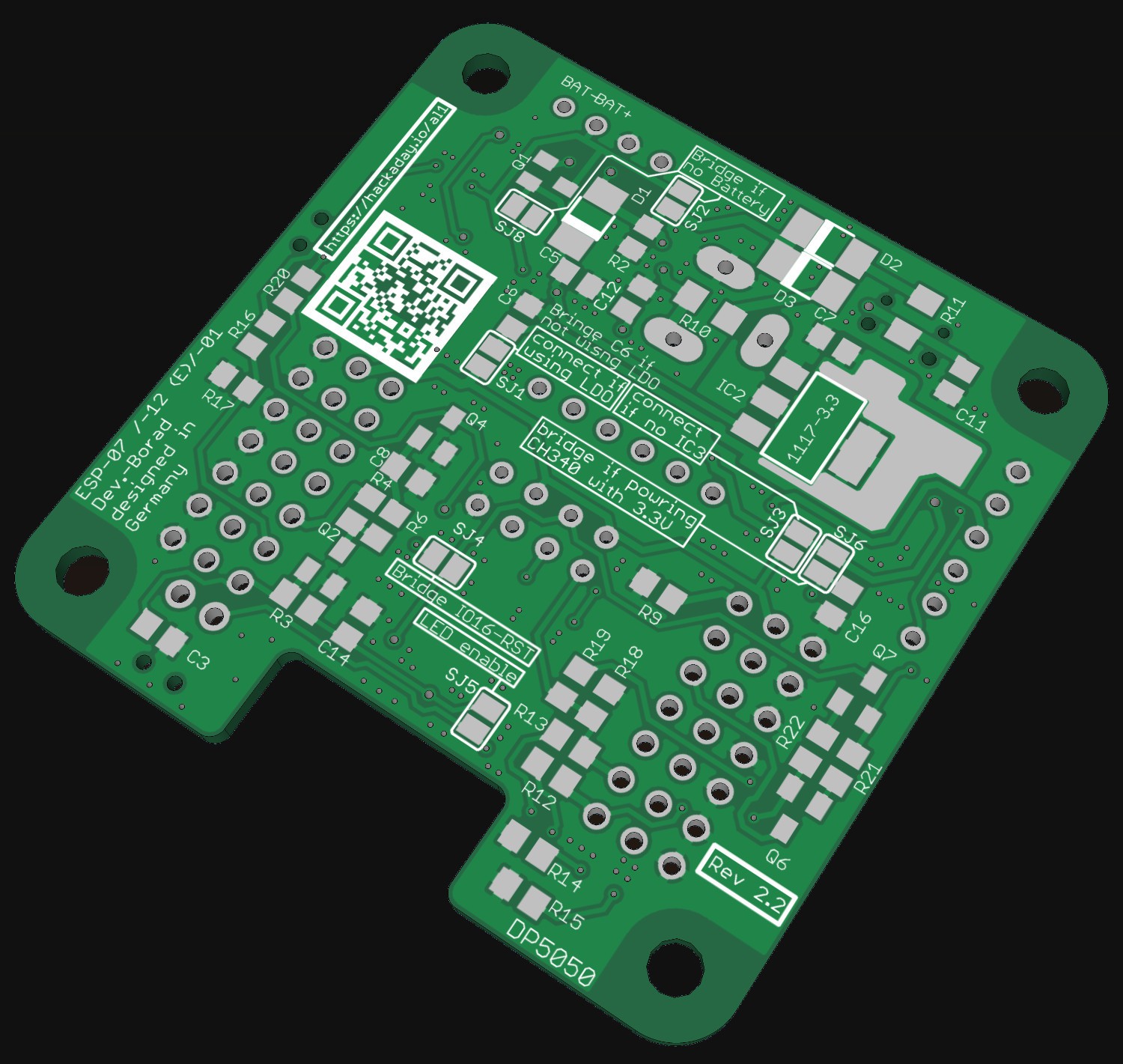
For the lipo Battery there is some charge and protection circuit prepared on the PCB. For charging a MCP73831 is used. As lipo Protection a used a DW01-P. In rev2 there is now also a load sharing circuit (source) available. The battery must me connected to 100mil pin header on the PCB.
The third way to Power this device is the 2,1 mm power jack. The center is positive. (There is is mistake on Revision 2.1 or earlier: The Center Pin is negativ!!!) This is the same Jack used in most Arduinos. Beside the Power Jack there is alternative a 100mil pin header.
The power source is selected automatically via schottky diodes.
For the main voltage regulator there are two options:
1. Standard LDO (AMS1117-3.3 easy to use totally common regulator datasheet)
2. Switch mode regulator (LM3671MF-3.3 much more efficient datasheet)
There are SMD jumper onboard to select one of them. Additional there is another small LDO. It can be used optional to power only the USB to serial converter. But the USB to serial converter can be also powerd from the main voltage regulator.
Adjusting the battery charging current
To set or adjust the charging current to different batteries you must select an suitable value for R8. The equation for the current is (according to the data sheet):The units are kOhms for R8 and mA for the calculated current. [MCP73831/2 data sheet p. 15]
Case
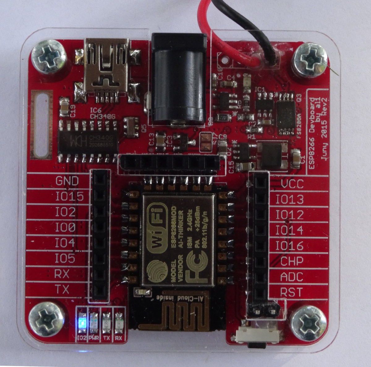
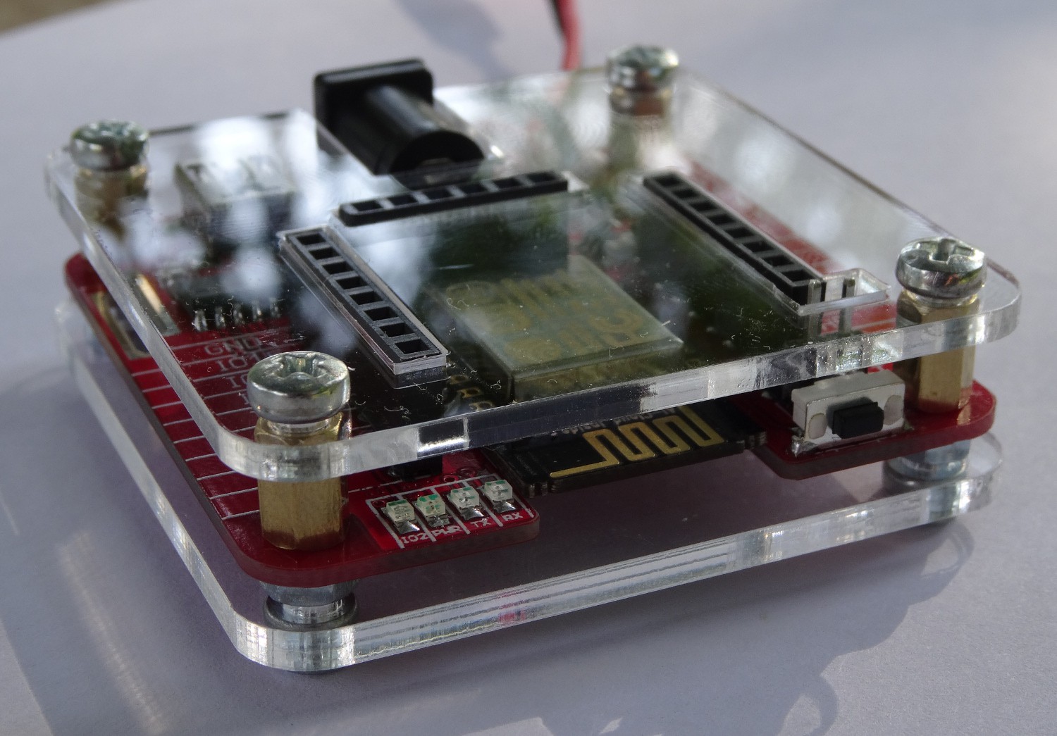
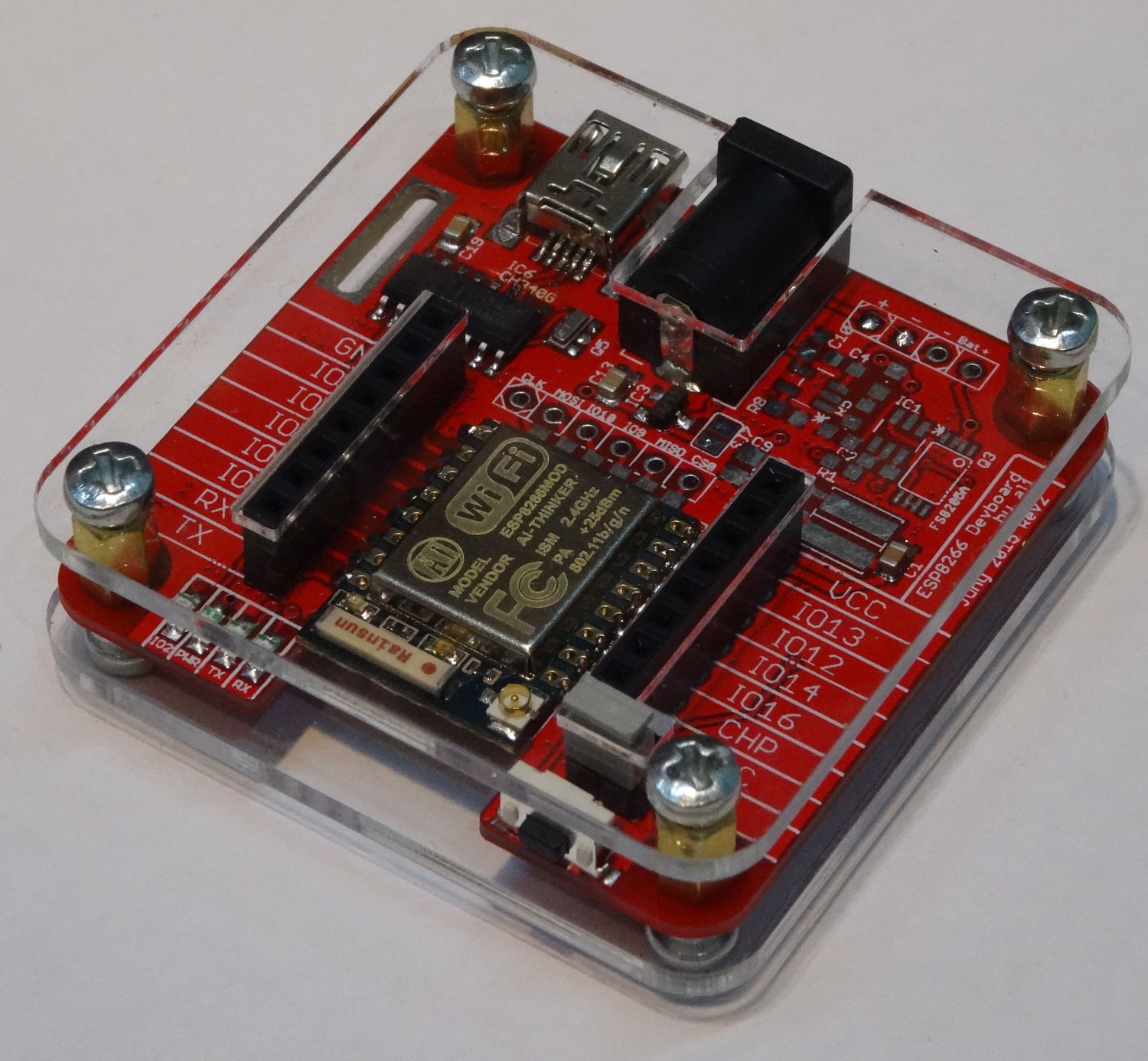
While the first revision has no case, only screw holes to mount the PCB somewhere (and these screw holes were to small) . I decided to make a case for the second revision. First I was thinking about a off the shelf case like this. But This was to small and I could not find one with is big enough but not to big. On the other hand most cases are non transparent and you will hide all your work. So I came up with the "Sick of Beige Cases" . This is nothing more than two transparent acrylic sheets screwed on both sides of your PCB. So I designed nice custom acrylic sheets for my modules....
Read more » Alex
Alex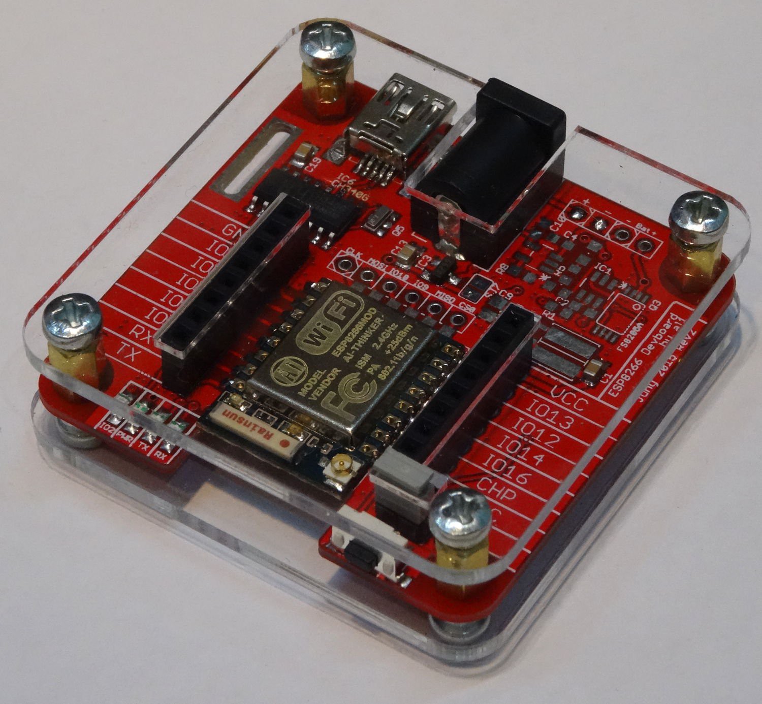




 ElectroBoy
 davedarko
 OzQube
Care to share your design on OSHPark?