-
Analog design IQ
05/24/2021 at 18:52 • 0 commentsPassive components
RF Attenuators
Inductors
- Measure inductance and capacitiance values with VNA: 3 methods depending on impedance
- Measure inductor saturation current
- Transformer saturation current can also be measured by applying DC-current to the primary winding, in series with an HF-decoupling inductor (many times the value of the inductor you want to measure and it should also have many times the saturation current). Then you can connect an L-meter to the secondary winding and start measuring.
Capacitors
- Measure capacitance value with DC-offset : Ceramic Capacitor with DC bias value measurement. LCR Meter
-
LoRa
02/20/2021 at 15:53 • 0 commentsLoRa
Why LoRa?
Gray coding, data whitening, interleaving, forward error correcting is all done in the transceiver chip.
- CSS (Chirp Spread Spectrum) :
- Resilience to interference
- Performance at low power
- Resistance to multi-path fading
- Resistance to Doppler effect
- Easy to decode, so can also easily be done on lower power simple devices.
- Gray coding : adds error tolerance
- Data whitening : induces randomness
- removing DC-bias in data
- long bit runs become less likely
- Whitening tends to distribute the data evenly across the radio channel’s frequency bandwidth, allowing the transmitter to run at a higher power without violating FCC regulations.
- Helps receiver synchronization
- Interleaving : Shuffling bits in a frame : reduces the impact of burst errors
- Forward Error Correction : Hamming codes
- 433MHz : less Free Space Path Loss (FSPL) than 868MHz.
- Actually as we're on earth and not in free space, we should use the MPPL instead which takes into account the Fresnel zone due to the reflections of the earth. The losses then increase with the 4th power of the distance.
- maximum effective bit-rate : 37.5kbps
- 256 byte FIFO, shared for RX & TX
- Critical parameters:
- spreading factor (SF):
- Each step up in SF means doubling of air time (i.e. bitrate/2). There's always one symbol per chirp. So increasing SF means lowering the chirp rate.
- Each step up in SF means an extra bit per symbol (e.g. SF7 = 7bit per symbol)
- Each step up in SF correlates to about 2.5dB extra link budget
- TTN uses Adaptive Data Rate (ADR) to use bandwidth and power more efficiently.
- modulation bandwidth
- higher bandwidth has the disadvantage of higher noise floor
- error coding rate
- spreading factor (SF):
Why not LoRa?
The maximum effective bit rate according to the SX1276 datasheet is 37.5kbps, which is done at 500kHz BW, SF6.
Where is that legally possible (ETSI EN 300 220-2 V3.2.1 (2018-06), Annex B)?- Band H : 433,050 MHz to 434,790 MHz, but with following limitations: ERP = 10mW, duty cycle = 10%. That leaves you 3.75kbps at 10mW.
All other bands are either too narrow, have even more stringent limits on duty cycle or have stricter power limitations.
Air time calculation : The fastest possible is SF7 with 250kHz bandwidth and a packet size of 120bytes. Aside from the thought that such a large frame size might not be a good idea, this results to 100ms air time per packet, which is corresponds to the maximum duty cycle of 10%. So we could send 120bytes/s = 960bits/s. We could also send two 50ms air-time packets per second, but these would contain only 50 bytes each.
LoRa module
Modules with integrated MCU
- Seeed LORA-E5
- RAK Wireless RAK3172 (comparable to LORA-E5), RAK4260, RAK4270
Low power, low cost modules
- Ai-Thinker Ra-02 (LCSC C90039)
- NiceRF LORA1278-C1
- RFM96/RFM98 Seeed 109990165
- RFM96W-433S2 : no longer available as module (except AliExpress etc.)
- RFM98W-433S2
- Difference with RFM96W-433S2 unclear
High power modules
NiceRF
- NiceRF LORA1268F30-433
- 33dBm
- works on 3V3 (max. 28dBm), needs 6VDC for 33dBm
- min. TX-pwr = 10dBm on 3V3.
- no coax-connector
- 38x20mm
- 5mA RX
- 2µA sleep
- LoRa RX-sensitivity (BW=62.5 KHz, SF = 12 CR=4/5) = -139dBm
-
NiceRF LORA1278F30-433- 30dBm
- 13mA RX
- 10µA sleep
- LoRa RX-sensitivity (BW=125 KHz, SF = 12 CR=4/5) = -139dBm
EByte
- E19-433M30S
- 3V3 to 5V
- 25x37mm
- 20mA RX
- 3µA sleep
- has u.fl-connector
- max. TX-power 29.5dBm
- LoRa RX-sensitivity figures unrealistic
- E22-400M30S
- 2V5 to 5V5
- 24x38.5mm
- 14mA RX
- 3µA sleep
- has u.fl-connector
- max. TX-power 21.5dBm
- LoRa RX-sensitivity figures unrealistic
HopeRF
- RFM98PW
- 5V to 6V
- 18x35mm
- 15mA RX
- 5µA sleep
- no coax connector
- max. TX-pwr=30dBm
- LoRa RX-sensitivity (SF12, BW=125kHz) = -136dBm
- Seeedstudio RFM98
- 2mm pitch, not breadboard friendly
- CSS (Chirp Spread Spectrum) :
-
RFID
11/10/2020 at 15:26 • 0 commentsRFID Writers
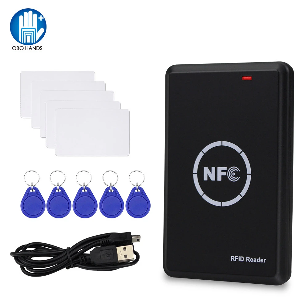
RFID Copier Duplicator 125KHz Key fob NFC Smart Card Reader Writer 13.56MHz Encrypted Programmer USB UID T5577 EM4305 Cards Tags
![]()
- Only works on Windows. On Linux dmesg shows a lot of errors. It's not recognized as virtual com-port or anything.
- When connected to the PC, it shows up as flash drive that contains the reader software.
- The reader software consists of a left side for 13.56MHz, the right side is for 125kHz.
- Bring a 125kHz tag within range. A double beep will indicate that the tag is recognized. Then press the "read EMID" or "write EMID" button.
- For 13.56MHz tags, the functionality is unclear.
- It can write empty 125kHz tags delivered with the 5YOA reader, but it can't overwrite them
- Also reads my own created RFID tag.
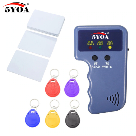
Handheld 125KHz EM4100 RFID Copier Writer Duplicator Programmer Reader + EM4305 T5577 Rewritable ID Keyfobs Tags Card
![]()
- Based on a PSoC. Nothing much left to hack. No method to extract read tag data.
- Doesn't read my own created tag.
- Use: bring tag within read range and then press read or write button.
- Can rewrite the tags delivered with it.
Own designs
RFID Reader modules
-
Mid-range MCU selection : STM32
10/22/2020 at 19:45 • 0 commentsRaspberry Pi Pico
Good support, not suited for low power (>180µA deep sleep)Blackpill
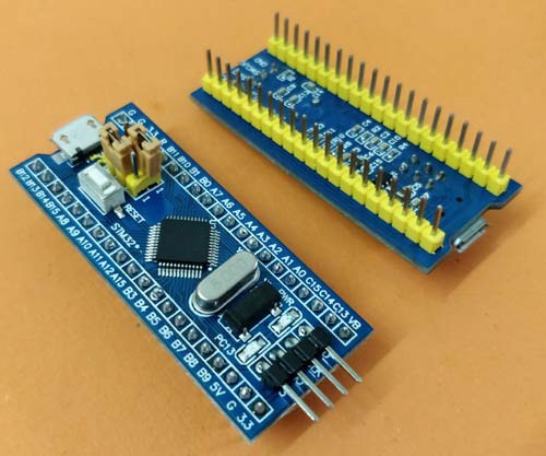
Upgrade to Bluepill.Bluepill![]()
- More info about debugging
- Small
- Bread board friendly : fits on a 2x20pin, 0.6" row spacing socket
- Cheap, around €1.5
- low quality
- some components need to be replaced (to fix USB enumeration, to fix RTC)
- low power possible
- no embedded ST-Link that consumes power
- replace LDO for low power
- Supported by platformio (64KB max. code size by default, but with platformio it seems to work to upload, debug and run programs > 64KB)
- external ST-Link needed for debugging
- no wireless connectivity
- old MCU (RTC is only a simple counter, no calendar functionality)
- Black pill seems to be a performance upgrade to this one.
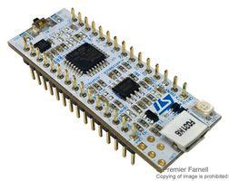
Nucleo 32
![]()
Why Nucleo32?
- Small, the 2x15pins fits in a 2x16 0.6" row spacing IC-socket (Digikey 2057-ICS-632-T-ND)
- Apparently pin-compatible to Arduino Nano. To be confirmed.
- 3V3, which is easier to interface to other electronics than the 5V boards.
- Integrated ST-Link debugger. Reduces the mess-o'-wires on your breadboard.
- Cheap <€10 from official sources (Digikey etc.)
- Good build quality, unlike the Chinese boards where you have to replace components that had the wrong value, are less-functional clones or that were otherwise unsuitable.
- A whole range of boards, with different MCUs. Some low power, some good processing capabilities.
- Good documentation
- Supported by PlatformIO (Arduino and other frameworks).
- Smaller than Blue Pill, but less GPIO pins
- Arduino Nano footprint compatible
- STM32Fxxx
variants not suited for low power. They need the clock signal from the ST-Link, e.g. if the UART baud rate is greater than 9600baud. - STM32Lxxx variants may be better for low power applications. To be investigated.
It might not be low power because of the integrated debugger. There might be ways to leave the debugger unpowered. These boards lack wireless connectivity.
ST-Link firmware
The ST-link firmware must be upgraded to make the virtual COM-port (VCP) work properly. The software to do this can be found on the ST-website. This should be the first thing you do with the Nucleo32 boards.
Variants
- NUCLEO-L432KC : 80MHz, 256KB flash, 64KB RAM, Arm ® Cortex ® -M4 32-bit MCU+FPU, TrustedParts (<€10)
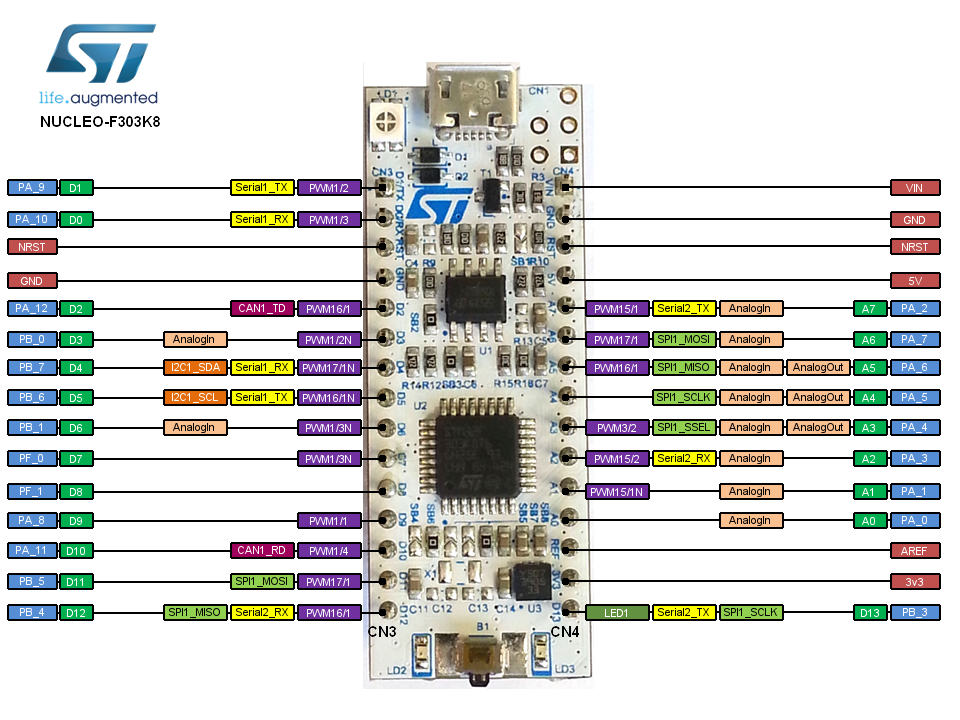
- NUCLEO-F303K8 : STM32F303K8T6 72MHz, 12KB RAM, 64KB Flash
- Only 12K RAM
- 12bit DAC, maximum update frequency with Arduino analogWrite() is 87kHz (12bit) and 100kHz (8bit).
Default: A4 connected to D4, A5 connected to D5. - Only A3 works as DAC.
- 12bit ADC
- Arduino ADC-code is hopelessly inefficient : analogWrite(A3, analogRead(A6)); takes 208µs. Which means we could process real time audio with a maximum sampling frequency of 4.3kHz.
- Careful with D2 as IRQ-pin. I had problems with it on a SX1278. Not sure why. On the Nucleo32 schematic, there were no connections.
- Default pinning :
- SPI : D11, D12, D13
- User manual
-
HAM stuff
02/06/2020 at 20:22 • 0 commentsHow Belgian legislation discourages HAM-radio
- After passing the practical exam in your local HAM-section, the theoretical part of the exam only takes places at the BIPT offices in Brussels
- You require an operating certificate, which allows you to use a radio. The allowed bands and transmission power depend on your HAM-license. This license allows you to use radio equipment, not to own it.
- If you own radio equipment, this must be registered, resulting in a station permit. This permit only allows you to own radio equipment, not use it. Station permits are only distributed to people with an operating certificate.
- Costs:
- Theoretical exam BIPT : €50 (includes operating certificate for first five years)
- Operating certificate renewal : €25 (5 years valid)
- Station permit : €51 (file cost) + yearly €51.
So if you own only a single €100 VHF-UHF handheld, you'll have to cough up €50 for it every year. That's only for owning it. If you want to use it as well, that'll cost you another €5/year. This will surely turn out to be a very expensive HT in the long run.
HF
- Choose the right SDR
- SDRplay RSP1A is a PITA to setup in Linux. Luckily someone has the hard work for us already and created install instructions. You'll also need the binary driver from the SDRplay website (Version 2.13.1 on FEB 2021). It worked only once. After that, the RSP1A was detected in CubicSDR, but it no longer became active. I had to delete the ~/.CubicSDR/ to get it working again.
- GQRX seems even more of a hassle to setup in Linux with this unit.
- In Windows there's SDRUno which is easy to setup, but it's complicated to work with. SDRUno is for advanced users.
RTL-SDR:
Antennas
- PA0RDT Mini Whip Antenna and a note about grounding. You can buy an SMD version online.
11m & CB-band
Allowed TX-settings for CB (without license): 12W SSB, which corresponds to 48W AM. See more legal info here.
VHF/2m/144MHz-band and UHF/70cm/440MHz-band
Radios <€100
PMR446:
- Midland G9 Pro C1385 LPD/PMR
- popular for airsoft
- PMR446 + LPD433
- 0.35µV sensitivity (@12dB SINAD), 70dB adjacent channel rejection
- headset only costs €3.64 on AliExpress. This can be cut to allow for connection to an audio interface.
- has accessory port for mic and speaker pinout
Ham:
- HamShield on Kickstarter
- Other HamShield on Tindie
- Which BaoFeng Radio Should I Buy, Are There Better Options?!? | HAM Radio Crash Course!
- Handheld Radio Comparison & Review
- Yaesu HT Deep-Dive, which is the best?
- Top 7 accessories for Baofeng UV-5r ham radio
Baofeng UV-5R
Baofeng BF-F8HP
Yaesu FT-65
most popular
spurious emissions
bad menu interface
AliExpress €22 (might be conterfeit)3rd generation of UV-5R
AliExpress €30 (might be conterfeit)
Buy through Amazon links of HamRadioCrashCourseInside review
seems to be an improved Baofeng UV5R (uses same chipset)
newer version of FT60
TX power:- H = 37dBm
- M = 34dBm
- L = 27dBm
0.2 µV sensitivity (@ 12 dB SINAD)
M-plug style (earpiece)
spec sheet
Hamshop.nl €86
DIY programming cableAntennas
see more on 434MHz antennas.
What can you do with it?
Satellites (if you attach a high gain antenna)
- When does the ISS pass overhead? (145.8MHz voice down-link from satellite)
- $50SAT Dropbox info
- What amateur satellites are currently passing over?
Commercial FM stations
- 88-108MHz
Listen to extra info during cycling races
Belgium : 164.63125 MHz & 160.10625 MHz, both channels are 12.5kHz narrow-band FM. It wouldn't be Belgium again if it didn't require an extra license : €25/year. Set the Yaesu FT-65 to 6.25kHz frequency steps.
Local repeaters
Modem & TNC
- minimodem Ubuntu package
- Mini-modem with RPi
- RadioShield (RTTY, Audio FM)
- linpac & direwolf
- soundmodem Ubuntu package
- FDMDV...
-
Lab equipment
12/25/2019 at 11:15 • 0 commentsPower supply
MDP-XP Digital Power Supply Set
Spectrum analyzer (SA)
Vector network analyzer (VNA)
- NanoVNA a $50-$70 Ham Radio Antenna Analyzer? : 50kHz - 900MHz, more on HaD.
- PocketVNA
- MiniVNA: AliExpress (€272)
- Test Antenna Signal Pattern on the Cheap
RF impedance analyzer
Has only one port.
-
Wireless MCU platforms
12/21/2019 at 20:58 • 0 commentsESP32
The ESP32 development boards are not without their problems. Why keep using them anyway? The ESP32 IC only costs €2.31/pce on Digikey. Design a decent breakout board and done!
Well, if you don't want to design your own board, have a look at the Olimex ESP32-DevKit-LiPo. The version without antenna costs <€10, while it includes a LiPo charger. Moreover, it seems to be designed properly and it consumes only about 60µA in deep sleep (using a buck converter!).
Andreas Spiess ESP32 boards overview
Reduce the ESP32 Power Consumption : boards comparisonAi-Thinker NodeMCU-32S Wemos LOLIN32 Lite Wemos D1 mini fits on a breadboard
Improvements:
* needs a 100nF from #EN to GND to fix firmware upload problem.
* pin labels only on bottom side
KS0413 keyestudio ESP32 Core Board
Use the ESP32-IO board (Keyes KS0465) for easy breadboarding and pin labels
platformio : NodeMCU-32S
holds a ESP32-WROOM-32D
Chip is ESP32D0WDQ6 (revision 1) module
Digikey (€8.25)
schematic
Velleman VMA109
AI-Thinker nodemcu_32s AliExpress
AliExpressdiscontinued
platformio : lolin32
AliExpress blog AliExpressAliExpress
AliExpressAi-Thinker NodeMCU-32S
3V3 LDO
This module has a very poor performing AMS1117-3.3 (Iout=1A, dropout voltage = 1.1V). The
If you want a SOT23-5 package, you can use the Richtek RT9080-33GJ5 has a 2µA quiescent current. Has only 310mV dropout voltage and can deliver up to 600mA. In case it's not available, you can order the ME6211C33M5G from AliExpress (40µA dropout voltage and pin compatible to the RT9080).
The ESP32 consumes 380mA peak.
Great resource about ESP32 boards and their power consumption.
Patch for firmware upgrade
![]()
0603 100nF between #EN & GND (0402 would have been easier to solder) ![]()
- Which ESP32 pins are safe to use? Excel sheet
- pin 14 remains 500ms high at power up.
- not 5V tolerant (although it might work a while)
- ESP32-WROOM-32D
- 4MB SPI-flash by default (8MB &16MB) available on Digikey
- no SPI-ram
- 240MHz
- Micropython
- https://github.com/espressif/esptool : pip3 install esptool
- download & install Micropython : https://micropython.org/download/esp32/
- Getting started with Micropython on ESP32
- REPL will be available on virtual COM-port (/dev/ttyUSB0)
- IDE : Visual Studio Code with micropy-cli
- rshell :
- rshell -p /dev/ttyUSB0
- cp main.py /pyboard
- rsync . /pyboard
- repl : start repl
- Ctrl-D in repl : soft reboot, restart program
- Ctrl-C in repl : stop running program and return to prompt
- Ctrl-X in repl : back to rshell
- rshell -p /dev/ttyUSB0
- Arduino
- VSPI-port is default SPI-port.
- More popular platform than the nRF52840 (20x google search results)
- Bluetooth 4.2 + Wifi 2.4GHz
- Programming : C++, Python
- Easier ESP8266 Development (most might be applicable to ESP32 too)
- low power modes: 100nA (power off) to 10µA (RTC + RAM retention)
slow FPU, not suitable for codec2 (see Andreas Schweiz)
TTGO LoRa32 T3_V1.6
nRF52840
- Long Range Bluetooth 5, Bluetooth mesh, ANT, 802.15.4, Thread, Zigbee
- 64 MHz Cortex-M4 with FPU
- existing codec2 implementation on nRF52832 (which has same CPU)
- 1 MB Flash, 256 KB RAM
- Programming : C++, Python
- low power modes: 400nA (power off) to 3.2µA (RTC + RAM retention)
LoRa boards
- SX1278 (137MHz to 525MHz)
- SX1276 (137MHz to 1020MHz)
RisingHF RHF76-052
- Product info
- Bands : 868MHz (less power) & 434MHz (most power)
RisingHF RHF78-052
- Bands: 434MHz only
- EC-Buying Ali Store : €5.34/pce
RAK Wireless RAK811
- RAK811 ($11), directly from RAK Wireless (+$24 shipping) (more expensive on AliExpress)
- Which ESP32 pins are safe to use? Excel sheet
-
Power analyzer
10/20/2019 at 09:26 • 3 commentsAfter some google searching, I came across the Nordic Semi Power Profiler Kit II. So why make it when there's already an affordable COTS-solution that has the features I need? The desktop application runs in Linux as well.
The DIY-route starts here...
One of the applications of a differential voltage probe is to measure voltage over a sense resistor. For low power applications, the current drawn can be quite small, which leads us to using a high value sense resistor. Unfortunately this also increases the source resistance of our voltage supply. So when the current suddenly rises (e.g. because the device wakes up), this might lead to a sharp drop in supply voltage to the device, even powering it down in the worst case.
The Elektor MicroSupply (Elektorlabs 9/10 2019) is Elektor's solution to measure power of low power devices. It has the following features:- built in ADC to measure voltage & current : we will use an oscilloscope for that, so that we're able to measure fast dynamic behavior (>1kHz sampling).
- built in DAC to set power supply voltage : we will use an analog input pin. The voltage that the user connects to that pin will be used as output voltage. The user can simply connect the 3V3, 5V or another voltage that is already present in their device. No need for a DAC.
- The power supply itself also has its issues. An opamp is used as active element in the control loop. The supply voltage is limited by the opamp supply voltage. The opamp itself is quite expensive >$2.
- Elektor tackled the problem of the big dynamic range by using a 100ohm sense resistor and using three LT1789 instrumentation amplifiers, each set to a different amplification factor : 1x, 10x & 100x. This has some downsides:
- Two types of LT1789 are needed.
- The instrumentation amplifiers are expensive : $3.70/pce.
- The VoutMin of the LT1789 is 100mV. So an extra offset is required. This is provided by an LT1790, another expensive part from Linear.
- A BC847 is used as pass transistor. This seems a bit under powered:
- VinMax = 12V
- VoutMin = 1.5V
- IoutMax = 40mA
- => P(T1) = (12-1.5)*0.040 = 420mW, which is too much for the 250mW BC847.
The Elektor designer also thought of using a single instrumentation amplifier with switchable sense resistors, but they didn't see the benefit from it.
Cheaper implementation
Single differential amplifiers with multiple sense resistors
![]()
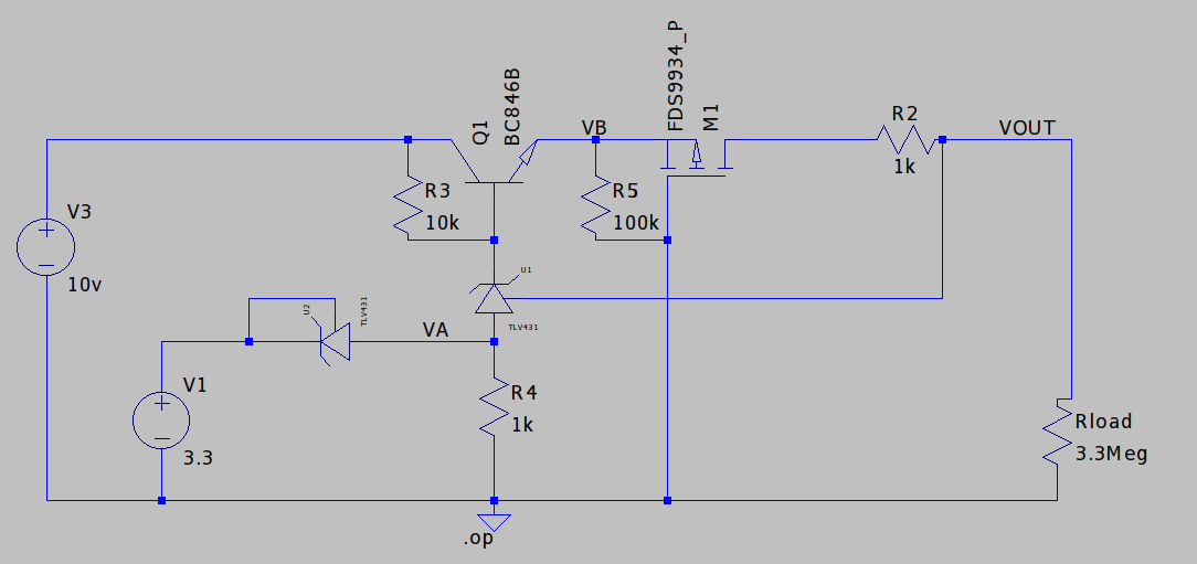
High side potentiostat to overcome the burden voltage (=voltage drop over the sense resistor). The working principle of this power supply is quite simple. Some calculations:
- V(R4) = V1 - Vka(U2) = 3.3 - 1.24V
- Vout = V(R4) + Vref(U1) = (3.3 -1.24) + 1.24 = 3.3V
So the power supply output voltage is equal to the analog input voltage V1.
The sense resistor R2 is switchable with the gate of M1. There could be many PMOS-transistor / sense resistor combinations mounted in parallel with M1 & R2.
Low current measuring techniques
Many sources refer to the transimpedance amplifier. The advantage is that it avoids big sense resistors and big burden voltages. The disadvantage is that a negative power supply rail is needed.
- Measuring nano amperes, Paul Rako, EDN 4/2007
- Simple Micro Ampere Meter Circuit, P. Marian
- Accurately Measuring Nanoamperes - Test Equipment Depot
- ACCURATELY MEASURE NANOAMPERE AND PICOAMPERE CURRENTS
- Low level measurements handbook : Check out "FIGURE 1-11: Feedback Ammeter with Selectable Voltage Gain"
- Tips for measuring small currents, Circuit Cellar 294
- Microcontroller Power Consumption Measurement Based on PSoC
- CA3420 Picoammmeter, see also CA3420 datasheet
- LTC1047 pico ampere measurer
- µCurrent Gold (LTspice simulation)
- Current Ranger :
- There's a USB port for logging, but for best accuracy, you should disconnect it ?!?
- The device seems to be easily damaged by careless users.
- There's clearly a need for DC-isolation in this device, but it's not provided. ...
-
Low end MCU Selection
10/13/2019 at 08:56 • 0 commentsRequirement
- low power : 3V3 or lower, not 5V powered
- at least 7 GPIOs, 9 preferred. We don't want to read the status of the switches with an ADC.
- as small as possible
- cheap
- easy to solder
- Availability : 2nd sourced
- PlatformIO / Arduino support
The Arduino support seriously limits the choices. 8MHz on a 1V8 AVR-architecture is out of spec. Higher supply voltages are needed, which imply the addition of a boost converter when powering with two AA-batteries.
Using AVRISPmkII on Linux requires a rules-file for udev:
SUBSYSTEM!="usb_device", ACTION!="add", GOTO="avrisp_end"

# Atmel Corp.JTAG ICE mkII
ATTRS{idVendor}==”03eb”, ATTRS{idProduct}==”2103″, MODE:=”660″, GROUP:=”dialout”

# Atmel Corp. AVRISP mkII
ATTRS{idVendor}==”03eb”, ATTRS{idProduct}==”2104″, MODE:=”660″, GROUP:=”dialout”

# Atmel Corp. Dragon
ATTRS{idVendor}==”03eb”, ATTRS{idProduct}==”2107″, MODE:=”660″, GROUP:=”dialout”

LABEL=”avrisp_end”
Save this file as /etc/udev/rules.d/60-avrisp.rules
Choices
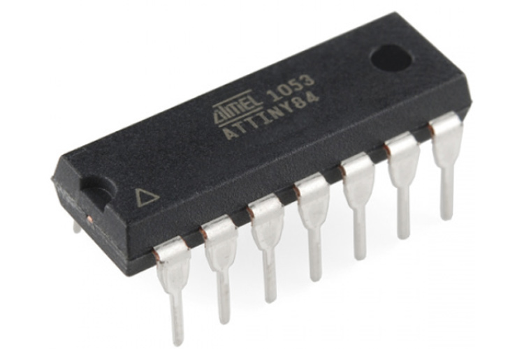
Bare bone MCU
![]()
The smallest/cheapest MCU that PlatformIO supports is the ATtiny24A/44A/84A family. They can be had for €0.80 to €0.90 a piece. SOIC-14 will be the preferable package.
This can be used with PlatformIO. See here for a demo-setup.
The ATtiny441 and ATtiny841 are pin-compatible parts with some extra features such as two USARTS (HardwareSerial ports).
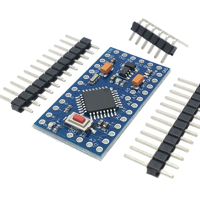
Arduino Pro Mini 328 - 3.3V/8MHz
![]()
- Newer versions have four extra GPIOs : pin A4, A5, A6 & A7. These are located two by two on the right hand side of the MCU. Older versions have only two extra GPIOs.
- Requires an FTDI serial USB converter for programming.
- Warning! : When using a TTL-3V3-WE cable, the signal levels are 3V3, but the VCC level is 5V! The problem is that this FTDI VCC pin is directly connected to the 3V3 VCC pin on the Arduino.
- Either disconnect FTDI VCC or connect it to the RAW pin of the Arduino Pro Mini.
- 5V on VCC is no problem for the Arduino Pro Mini, but it might be disastrous to your connected 3V3 peripherals.
- 33 x 18mm
- fits in a DIP (2x12 pins, 0.6" row spacing) socket. Height can be reduced by inserting the headers from top side and solder them from bottom side.
- Sources for DIP socket :
- Where to buy : AliExpress 32341782884
- Getting started : Sparkfun : Using the Arduino Pro Mini 3.3V
- Burning the bootloader. There's a bootloader present upon delivery. In case you removed it and want to program it again:
-
Audio module
10/09/2019 at 17:56 • 0 commentsMost clocks use sound to wake you up. This clock is no exception.
A little "DFPlayer Mini" module does all of that, also MP3 decoding. It even includes a speaker driver.
Yue Xin YX5200-24SS module
! Check for short circuit between pin 3 and ground! The corner of the SD-card connector is very close to pin 3. Two of my boards had that issue.
Works like a breeze with the platformio. Be careful to connect your module correctly. I've already destroyed one by wrongly connecting it and nearly killed a second one. Strange...the polarity is clearly marked on the module.
- Decoder IC : (auto translated datasheet)
- AliExpress $1.17
- Modules
- DFplayer Mini module
- SMARTWAV
- Flyrontech as FN-M16P, module datasheet can be found here.
- Embedded Adventures MOD-1021
- User experience from Markus Wobisch
- Library:
- The official library from DFRobot locks up when making too many calls to it.
- DFPlayer Mini Mp3 by Makuna is a better alternative
- Power supply : The DFPlayer Mini sometimes crashes when it's powered by the 3V3. Maybe my 3V3 supply can't deliver enough current. I didn't have this problem when supplying it with 5V.
- Before copying music files, normalize their volumes.
sudo apt install python-rgain
replaygain --force *.mp3
I have the impression that it works well on a PC, but that the DFPlayer ignores the normalization. I have also tried to use Audacity using the procedure described here, but also with disappointing results.
sudo apt install ffmpeg
ffmpeg -t 430 -i 2.mp3 2b.mp3
One song ended in a 1min20s silence. The ffmpeg command allowed me to strip that pause off.
- There are two options for audio output: headphones (stereo) and speaker (mono).
- Speaker output is generated by the on-board amplifier. According to the VCC, GND and speaker connections, the amplifier is a PAM8302A (or LM4871, or XPT4871, or YX8002-8S). This one can send 2.5W into a 4ohm speaker. That's certainly loud enough.
- The speaker output of the module certainly needs filtering to reduce EMI.
- The speaker sound lacks low frequency content. The input coupling of the PAM8302A might have a too high corner frequency. Let's see what other designs are using:
- Elektor "PAM8302A Audio Amplifier" (issue June 2018) : 180ohm in series with 220nF
- Adafruit 2130 : 100ohm in series with 1uF
- DFRobot advises to add a 1K resistor in series with the RX-line (pin 2) to reduce noise.
- See also Markus Wobisch schematic to reduce noise.
- EMI precautions : see Elektor "PAM8302A Audio Amplifier" (issue June 2018)
WTV020 module- $1.93 module from AliExpress
- SMD (only components on one side)
- Also used by Sparkfun
- ADPCM, WAV, no MP3
- serial interface : DATA + CLK
GeneralPlus GPD2846A moduleThis module doesn't seem to allow control by a MCU, except through USB.
GeneralPlus GPD2856A moduleThis module doesn't seem to allow control by a MCU, except through USB.
PWM outputIt doesn't look like there's already an established solution for the STM32 platform. This will require lots of work.
The cheapest option would be to generate sound using PWM, but it requires some work. The sound files also need special conversion before storing them to flash. An output amplifier is needed for connection to a speaker.
Arduino Wave shieldIt uses a MCP4921 DAC and an SD-card. Both are SPI devices, but they're connected to a different bus.
-
DCF77 decoder
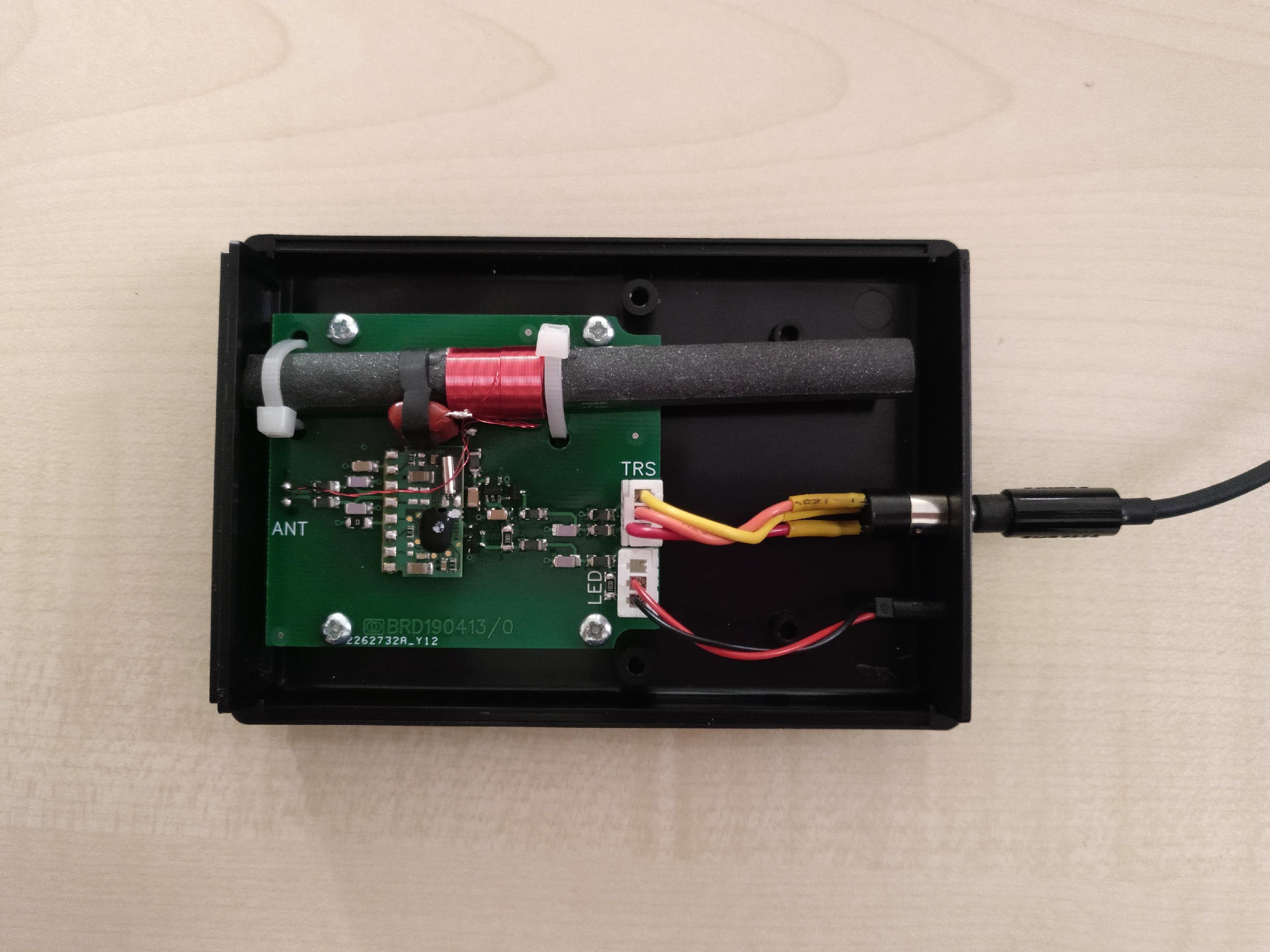
10/09/2019 at 17:49 • 0 comments![]()
Assembled unit (lid removed to show internal construction) Design
Schematic design and PCB layout can be found on EasyEDA.
Housing
The DCF antenna doesn't work well when it's in proximity to EM-noise sources. Possible noise source are the rest of the electronics of the clock or a laptop. The solution is to put the DCF-antenna and the decoder in a separate housing. It might not be necessary to use the separate housing once the clock is properly designed instead of using the breadboard and flying wires.
Steps to follow:
- Using the Hammond 1593NBK.
- Converting the DWG file to DXF using CloudConvert.
- Cleaning up DXF using LibreCAD
- importing in EasyEDA.
Main components
- DCF antenna : HKW AFET 77.5 - 10x100/70
- DCF decoder : HKW EM6 DCF 3V
- Output drive capability is only 30µA!
Connector
It should be easy for the customer to find a suitable cable assembly to connect the box. The connector should also be small and low profile.
- Stereo audio jack cable :
- flexible, cheap, readily available
- user might be tempted to connect headphones. This must be avoided. At the least, the headphones shouldn't be damaged.
Modular jack cables:- 4pins, 6pins, 8pins, common use in POTS telephony and ethernet.
- Ethernet cables are not that flexible.
- Big connector. Might not fit inside the housing
The initial idea was to mount a TRRS audio headset socket directly on the PCB, Doing this would make it hard to correctly drill the needed hole in the front panel. Moreover, such a connector, which needs to be placed against the wall of the housing would require a longer PCB than stated in the datasheet of the box.
Two JST XH connectors will be used instead. One connects to a panel mount TRRS audio headset socket. The other connects to a panel mount LED.
Cable assembly
Many audio cables are constructed as two pairs of two wires. So the left and right channel each have their ground wire in close proximity. The ground wire is connected to the sleeve. To take advantage of that cable configuration, the GND signal is here also connected to the sleeve.
JST XH Signal Audio jack 2 3V3 Tip 1 OUT Ring 3 GND Sleeve Time sync
Five options for setting time have been considered:
- Long wave time signal
- DCF (EU), MSF (UK), WWVB (US)
- cheap modules only have a few 100km range.
- more future proof than RDS.
- signal easily disturbed by electronics in the vicinity (laptop, SMPS, ...) .
- RDS
- no user interaction required
- indoor use possible
- EOL in Western Europe
- Timestamp only sent once a minute. When the reception quality is bad, you might have to wait some minutes to get the correct time.
- NTP : requires input of SSID & WPA-key to the alarm clock. The most elegant way seems to add a QR-code on your device, showing its preferably unique SSID & WPA-key. The users scan this QR-code to connect their phone to the device's AP. Upon scanning, the smart phone opens a webpage. This webpage contains a list where you can select the SSID of your home network. Directly below it, there's a text box where you can type the corresponding WPA-key. Upon saving the settings, you're done. The pitfall is that the browser on your smart phone doesn't run as a root user, so it has no access to your wifi credentials. This requires the user to copy them manually. This can be a bit of a burden, leading to complaining users: "Where's the WPA-key again?", "Pff, such a long key..." and "How do I type these strange characters?..." Instead of putting your device in AP mode, you could transfer wifi credentials through NFC, audio, sound or through light. I don't see any benefit in these methods : requiring more hardware, requiring custom apps on your phone, not solving the issue of getting access to the WPA-key. The AP-mode technique would also allow you to easily add other parameters that require some form of setup by the user.
- GPS : needs...
-
Alarm display
10/06/2019 at 09:02 • 2 commentsAlarm display
Many silly alarm clocks don't show the alarm time by default. You only see a dot indicating there's an alarm active. To view the alarm time, some buttons need to be pressed.
To distinguish it clearly from the clock time, a smaller LCD display will be used. It will allow to verify the alarm time before going to sleep. It doesn't hinder that the alarm time can't be read without eye glasses.
TM1637 modules
A chinese 7-segment 4 digit module with TM1637 driver is very cheap. Costing €0.51, it's only €0.10 more expensive than a bare 7-segment 4 digit display. There's little to be gained by integrating the driver and the display on the main board instead of using a module.
These modules use a custom protocol that resembles I²C, but is not compatible to it. So you'll need to sacrifice two digital IO-pins for this module. Luckily someone wrote a driver already (Adafruit LED Backpack Library) to interface these modules to your microcontroller.
HT16K33 modules
Adafruit's LED backpacks are based on this one. Most of the modules are sold without LED display. If you want one with display, you'll pay €1.90 on AliExpress.
I don't know how thought it was a good idea to make the mounting holes so small. You need to drill them out to put a 2.5mm screw through them.
This module has an I²C interface.
Nokia 5110 module
This module has an SPI interface. It requires 5 IO connections.
OLED displays
Very bright, but small. These cheap modules will also be very susceptible to screen burn-in. This makes them less suitable for this application, where the alarm time will be shown continuously.
-
Main display
10/06/2019 at 08:58 • 0 commentsMain display
To be readable in the dark without glasses from about 0.5m distance, the characters should be around 50mm high.
There are a few options here:
- numeric or alpha-numeric LED segment displays, sized 2.24" or 2.3". These are used in the nice Alpha Clock Five. These displays are expensive (Digikey €5/pce) and not very standard.
- LED dot matrix 5x7 5mm, not standard, not cheap
- LED dot matrix 8x8 5mm, about €1.5/pce, 2088AS or 2088BS, common anode or cathode.
- LED matrix 8x8 3mm common anode, €0.60/pce, tests with a 5mm LED dot matrix with 3x5 pixel font (35mm high) showed me that it's readable without glasses from 0.5m distance.
- LED Panel P10 Red, AliExpress $12.68. Definitely the cheapest 32x16 panel, but the size is 320x160mm. It's too big. There are LED modules with smaller LED spacings, but the outside dimensions don't change much.
- LED Panel P3 RGB, AliExpress €18.51. 192x96mm, 64x32 panel
After putting a lot of effort into making my own module for the 8x8 3mm LED matrix (see Tileable 8x8 LED matrix), I discovered that 32x8 LED matrices are on sale for close to no money (€2.93). These modules use the MAX7219, which is controlled by SPI. You could also buy an 32x16 LED matrix (€6.89)/pce).
Writing first texts to display Development is ongoing : two 32x8 display units are stuck together with tape. I had some trouble writing data to the MAX7219 modules. It seems that only bit banging SPI works. Maybe that's because the modules are only powered with 3V3, while the MAX7219 requires at least 4V according to its datasheet.
All the libraries I tried (LedControl, LEDMatrixDriver, ...), had issues. I adapted the arduino-Max72xxPanel to suit my needs.
Choosing font
The font should be easily readable without glasses. So we want it as big as possible.
Font comparison The fonts have been recovered from the Xronos clock. That clock contains five different fonts of which four are shown here. The character '8' is chosen, because it's one of the most difficult ones to read. The two fonts on the right are easiest to read. The rightmost font has been chosen because it looks nicer.
-
Movement detection sensor
10/06/2019 at 08:50 • 0 commentsAt night, the display will be off, allowing you to sleep in complete darkness. If you wanted to know the time, you could just wave your hand to light the display. After a minute, the display will go off again.
I see two possible sensor technologies : PIR & radar.
The RCWL-0516 radar module is cheap, offers 360° detection, but consumes 4mA continuously.
The HC-SR505 PIR module is also cheap, has a smaller opening angle and consumes only microamps continuously. More info can be found here. It should work on 3V3, but when I do that, it stays in an eternal detection state. 5V is definitely needed. A comparison of this PIR sensor to another one can be found here.
-
Ambient light sensing
10/06/2019 at 08:49 • 0 comments- day mode brightness
- night mode brightness
- level control to switch between day and night
It would be better if this could be done automatically. Maxim Integrated has an application note concerning display brightness adjustment according to ambient light levels. They make reference to a logarithmic conversion proposed by Microsoft Windows.
Brightness mapping ambient-light levels to optimal screen brightness. f(x) = Screen Brightness (%) In the first implementation, the brightness adjustment involved three settings:
The APDS-9960 outputs integer light levels, which compare more or less to lux. The smallest non-dark light level that can be measured is 1 lux. As a result from the formula above, the minimum screen brightness (which corresponds to 1 lux) is 27%. All lower screen brightness levels would be unused because the APDS-9960 can measure light levels smaller than 1 lux.
The MAX7219 display panel only has 16 brightness levels. It would be a shame not to use them all. So a different brightness mapping will be used.
In the clock, the display brightness levels 0 to 15 are linearly mapped to brightness ratios of 27% to 100%. Then the inverse formula of the one above has been used.
g(x) = light level in lux, x=brightness level [0 15] Another problem with this formula is that it uses a computationally intensive logarithmic function. Instead of calculating a brightness setting for a specific light level, a lookup table will be used defining what light level corresponds to a certain brightness setting. There are only 16 brightness levels, so the lookup table doesn't take up much memory space.
Ambient light sensor selection
The clock should monitor the intensity of the ambient light in order to adjust the intensity of the LED array. Especially in the dark it can be quite annoying when the LED array is too bright. Many choices for sensing the ambient light are available.
Important factors that determine the choice are cost and sensitivity in the human eye light spectrum (390 to 700nm).
IC sensor
- More expensive
- More features (proximity sensing)
- Parts
- TSL2591
- Adafruit TSL2591 High Dynamic Range Digital Light Sensor
- Works fine with the hardwired I²C of the STM32 Blue Pill
- Gain x25 with 600ms integration time matches our application (max. 1254lux) perfectly. When the light level is higher, -1 is returned as lux value.
- The Adafruit libraries are using a blocking read function, which means the read function hangs as long as the integration time (up to 600ms) is not finished.
VEML7700- Adafruit 4162
- Reads Lux directly, should provide more stable and more reproducible readings
- Adafruit VEML7700 library: sensor detected, but readout remains zero on the STM32. 25KB for the example application!
- Mikroelektronika Ambient 6 Click : libraries in custom mpkg-format, not usable for other platforms
- DFRobot Gravity: I2C VEML7700 Ambient Light Sensor (0~120Klx). 20KB for the sample application. Output is constantly 0.12lux using the STM32.
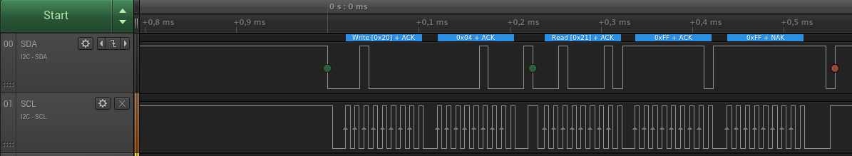
- The problem with the STM32 Arduino tool chain is that it doesn't send a repeated start. It sends a stop instead, followed by a start. This may be ok for most of the I²C devices, but the VEML7700 doesn't allow it.
- We might want to try a SoftWire I²C library on the STM32 as a workaround. I patched the SoftWire library to get the repeated start working. You can find the library here.
- Unfortunately, another problem arose : the SoftWire I²C library doesn't work simultaneously with the DCF-library. The DCF-library relies on the 1ms timer interrupt. The SoftWire library prevents it from working correctly in some way.
![]()
Capture from Wire I²C on Arduino Pro Mini : the VEML7700 returns data, there's a repeated start (green dot), not a stop after sending the address (0x04). In this case the sensor returns 0xFF, 0xFF. These values change...
- TSL2591
-
User input control
10/06/2019 at 08:46 • 0 commentsHaving only a 32x16 LED array to show data poses some limitations on the user interface.
The Nokia 3310 interface could be used as an example. There are three functions in three buttons:
- C : Cancel = go back
- Middle : Select or Menu (which is actually also select)
- Up/Down arrow to choose items
To help with navigation, on the top right, the path in the tree is shown. On the right, a line marker indicates the index of the menu item.
All in all that's very nice, but it forces you into a lot of key strokes. Instead of a menu with several levels of hierarchy, the different functionalities will be brought out onto separate switches and rotary encoders.
Rotary encoder
The problem with a rotary encoder is that there's no way to go back to a higher level in the menu structure. The workaround is to add a "Back" menu-item that points to a higher menu-level.
Filtered component list in Digikey for applicable rotary encoders with switch. These are quite cheap, so they can be readily ordered on Digikey, no need to wait for AliExpress.
Another drawback of the encoder is the high switch actuation force. For the Bourns PEC12R-series, is around 9N worst case. That's about the weight of three soda cans (on planet earth). This makes the rotary encoders unsuitable for horizontal actuation. When you pushed the switch, you would turn over the clock, or it would start sliding over the surface if you wouldn't be holding it with your other hand.
The Bourns PEC12R series has a plastic shaft. Rocking the shaft gently back and forth or left to right causes false contact switching. The shaft also feels a bit flimsy. Adafruit uses the PEC11-4215F-S24, which is now obsolete. The PEC11R-4215F-S0024 is the new part number. Presumably the metal shaft from the PEC11(R) series is more sturdy than the plastic shaft from the PEC12R.
Separate switches
Including the key cap(s), this is more expensive than a joystick if momentary switches are used.
Using keyboard switches, it's another story. There's a wide variety of push forces, key caps.
Because the original Cherry MX switches didn't accomodate for 3mm LEDs on a non-transparent key cap (which was what I had at that time), I opted to use SMD LEDs instead. That wasn't a good option. There's lots of light bleeding away on the sides. Another problem is that only the top half of the key cap is lit. Using 3mm LEDs doesn't solve that issue. 3mm LEDs with a wide opening angle are needed. Preferably the LEDs should also be high efficiency, as with charlieplexing, they might be driven with low duty cycles.
Keyboard switches are bigger than the ubiquitous 6x6mm momentary switch. In this case, it's advantageous as it allows easier control.
Touch screenA 6.2" or 6.4" touchscreen could be used (156 x 88 mm). This costs $6.24. Does a touchscreen have added value in this application that can justify the added cost? With a clever menu design, it can be very easy to use.
JoystickThis has all the necessary features:
- a button to select a menu item.
- up/down movement for selecting menu items in a list.
- left movement to go back to the parent level in the menu.
This single component can be used to implement the Nokia interface. It might be strange somehow that the movement to the right has no function.
One handed operation.
The look might be odd with such a joystick pointing out on the front panel.
Navigation switch aka 5 way switchThe cheaper version of the joystick. It uses switches instead of potmeters. So there's no way of measuring how far the button has been pressed.
The key cap must be ordered separately.
1-Axis Thumb wheelsVery cheap, about $1.08 for 10 pcs. According to Sparkfun, these parts are frequently used on portable MP3 players.
At least two of these would be needed. ...
Read more -
Clock IO panel R0
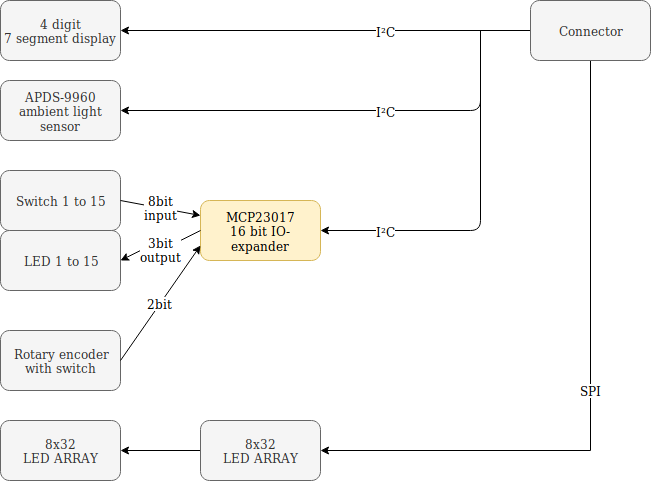
10/06/2019 at 08:14 • 0 commentsBlock diagram
![]()
First layout idea
![]()
IO panel with two times two concentric LED rings Nothing to be really happy with. This design is too large. There are three rotary encoders with an internal switch. The high switch actuation force of these switches prevents the panel from being used in a vertical position. You would top over the clock when you push the switch of a rotary encoder.
The three rotary encoders will each be replaced by a push button switch. There will be one encoder for general change of values. You push the switch to select that functionality. Using the rotary encoder you can then change the value at will. This kind of user interface is used on the R&S RTO200O series oscilloscopes.
The double rings of WS2812B LEDs are also eating up too much space. Let's replace these by LED bar graphs.
Second layout idea
![]()
LED rings replaced by LED bar graph The space consuming LED rings have been replaced by LED bar graphs. Each one needs 10 inputs, so it will take some effort to get these routed properly.
The button for setting the brightness of the LED array and the light sensor are not related to alarm settings, so they have been removed from this module. Functionality for setting LED array brightness should be physically located near the LED array, not on a separate IO panel.
So what's left?
- A menu button to cycle through the alarm settings (top left).
- top right: a button to set alarm hour & minutes
- seven buttons to enable the alarm for certain weekdays
- a button to set the brightness of the sun rise simulation with the corresponding LED bar graph.
- a button to choose the song to wake you + LED bar graph
- a button to set the music volume, with LED bar graph
- a single rotary encoder to change the value of a setting once the setting has been selected by a push on its button.
It all doesn't look to well: all those bar graphs... The rotary encoder is out of place.
Let's work out another idea...
Third layout idea
Why not incorporate the LED bar graph functionality in the LED array? We have plenty of pixels already there. Both sides of the LED array can be flanked with buttons. Alarm settings on the left, LED array settings on the right. The pixel row next to the button can be used as a virtual LED bar graph.
The LED array "PCB" and the clock-io-panel have been merged into a single PCB. This reduces cost and it will mechanical assembly easier.
Functionality overview at a glance, counter clockwise, starting at top left:
- setting brightness of sunrise simulation
- setting volume of alarm / music
- select alarm tone /song
- menu button for selecting the settings of alarm1 or alarm2
- seven buttons to enable/disable the selected alarm on a day of the week
- setting the alarm time
- setting LED array night brightness
- select at what ambient light brightness the day/night switch should occur.
- setting LED array daylight brightness
Alarm + LED array functionality merged into one IO panel. Connectors & ICs not yet shown
In the middle you can find :
- the LED array to show time & settings
- the ambient light sensor
- the rotary encoder to change the settings. The switch on the rotary encoder will not be used.
- seven segment display to show alarm time. It will only show the alarm time if an alarm is scheduled in the next 24 hours.
This clock-io-panel is bigger than the previous one, but 196x122mm will still fit on pretty much any night table.
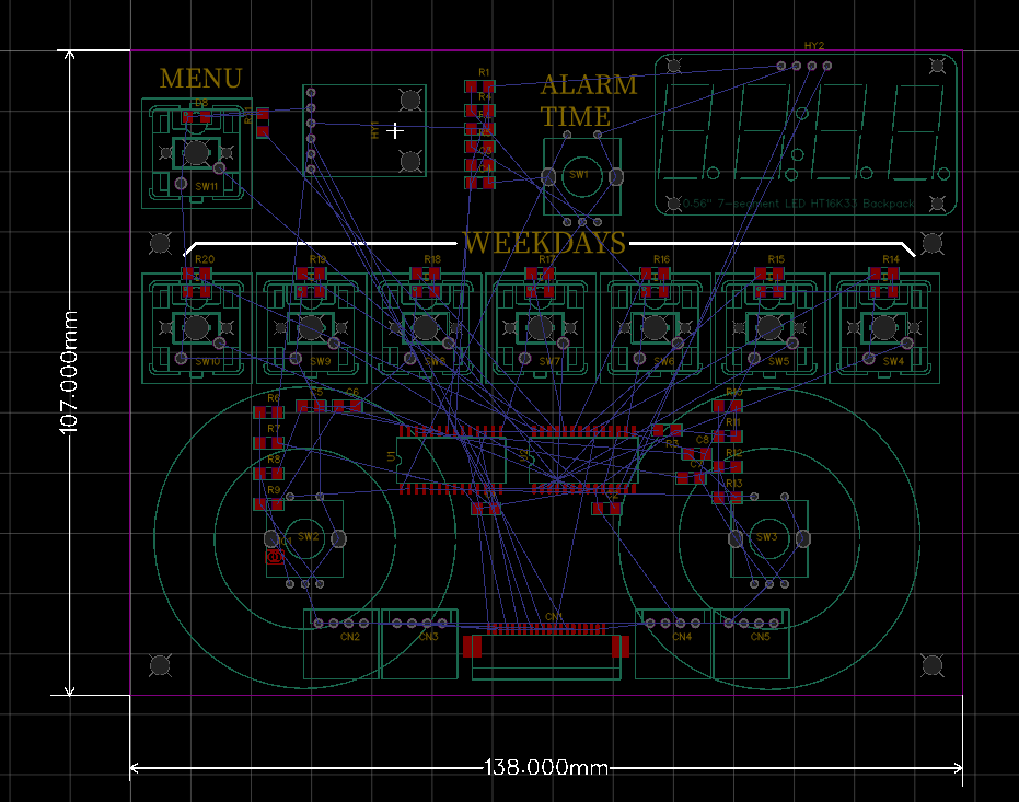
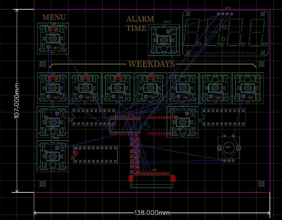
Layout for PCB Revision 0
Finished layout Some improvements with regard to the previous version:
- Switches moved to the edge of the PCB. On the previous version, there was no room between the switches and the LED array, which makes it harder to add a sturdy front panel later on.
- Grouping icons in groups of related functionality to improve intuitivity
- Changing some icons to make them more intuitive.
- Swapping led 7-segment...
-
Long wave time signal
10/06/2019 at 08:02 • 0 commentsCommercially available DCF77 modules
- Conrad (receiver+antenna)
- HKW antenna + HKW receiver (datasheet)
- Grupo Premo antenna
- Reichelt (receiver+antenna)
- Universal Solder (receiver+antenna)
An evaluation of these DCF77 modules has been done by [Udo Klein] and can be found here.
Signal quality tests with HKW antenna & receiver
I hooked up the antenna to the receiver. The receiver was powered by a Protrinket3V, which in turn was powered by a TTL-232R-3V3-WE. The DCF output was monitored using a Smartscope.
At first, there was no useful signal. I pulled out all the mains plugs to find the culprit. I found three of them:
- USBwire lead of the TTL-232R-3V3-WE
- Asus charger for Asus X550L laptop (only when DC-jack is plugged into the laptop)
- Power adapter for Fantasia Xaro Desk light (EAN 5414358095390).
Moving the antenna closer to the window, away from these noise sources solves the problem.
I also discovered that signal quality can vary strongly during the day. During programming the signal went very bad. After a few minutes it turned all of a sudden to a good signal again. Nothing in my house was switched on or off during that instant.
The DCF77 Analyzer/Clock v2.also uses an external antenna and receiver. I also get the best results when the antenna and receiver are on one breadboard and the rest of the electronics are on another breadboard. There needs to be at least 30cm space between them. The antenna should also be kept at least 30cm away from the laptop.
Decoding time
Visual indication
The problem I quickly encountered is bad signal quality from the module. Rotating the antenna helps, but you can't ask from users to do this for you. A solution could be to add a mono stable multivibrator to the DCF output that triggers on falling edges. It could have a 500ms timeout. If you connect an LED to it, there would be a visual indication of signal quality. The user should see the LED flashing at a 1Hz rate. If the LED stays on or off then signal quality is bad.

Thijs Elenbaas] uses edge triggering. In the presence of noise, this is not a good idea. In the image above you can see why. There are only three signal pulses (2 times 200ms, 1 time 100ms). All the other pulses are noise. I let this library run for 8 minutes without success. [Udo Klein] put quite a lot of effort in providing an alternative in his Blinkenlight project. Unfortunately this project only works for AVR architectures. I forked the library and added support for the Bluepill. The other big drawback is that it takes at least 5 minutes to sink. With a bad signal, this can increase up to 30mins. The library of [Udo Klein] also requires you to synchronize your clock to the DCF77. If you don't do this, you won't be able to recover the signal from the noise when the signal goes bad.
Scientific papers about DCF77 decoding can be found here:
- Daniel Engeler Performance Analysis and Receiver Architectures of DCF77 Radio-Controlled Clocks (DRAFT) (pdf)
- Filip ZÁPLATA, Miroslav KASAL, Software Defined DCF77 Receiver, RADIOENGINEERING, VOL. 22, NO. 4, DECEMBER 2013 (pdf)
- Martin Wierich "Ein digitaler DCF77-Empfänger mit hoher Empfindlichkeit", Diplomarbeit (pdf)
Capturing data from serial port
minicom -D /dev/ttyACM0 -b 115200 -C minicom.cap
Displaying data
It's quite easy to use Calc/Excel to convert the capture file from minicom to two csv files, each containing one column.
These CSV-files can then be used as PWL input data for voltage sources.
[jafingerhut] has done quite some investigation about finding the right package to show your data.
Online decoded DCF data can be seen here.
-
RDS
10/06/2019 at 07:48 • 0 commentsAfter evaluating the RDA5807M and the SI4703, I found out that it's hard to get good quality RDS-reception. I only tested on a breadboard. The air wire connections and the absence of a large enough ground plane aren't helping to get good reception quality.
The used development platform has an influence as well. The ProTrinket 3V, powered by the FTDI has a average 5dB better RSSI than the Nucleo STM32F103. On the Nucleo, it wasn't possible to receive four consecutive blocks without error. The SI4703 had to be set to RDS-debug mode to get at least some RDS-info.
RDA5807M
- This chip is based on the SI4703. The RDA5807M datasheet even contains statements that have been literally copied from the SI4703 datasheet.
- There's no error checking on the last two of the four RDS blocks. Block 3 and block 4 contain the useful data. The only way to "guarantee" data integrity is only passing on data that has been received twice identically.
- Reception quality is acceptable for audio, but not for RDS. There's only one station that gives me acceptable RDS reception.
- The RDA5807M has more or less the same settings as the SI4703, but these are located at other registers. So they're not firmware compatible.
- Very little info about the RDA5807 : 2 datasheets (in english) and two programming manuals (in chinese)
- Available on module by AliExpress
Si4703
- Extensive info available on SiLabs website
- Available on module by AliExpress
- If you need RDS, better to choose this IC instead of RDA5807M. The RDS reception quality isn't better, but at least you'll be told what RDS-blocks are valid and which ones contain too many errors.
Si4749
- RDS only, no audio
- hard to solder QFN package
- Acceptable price : €2.30/pce at Digikey
Si4731-D60
- Used in the more recent versions of the taiwanese Sangean WR-2.
- Expensive : €13.85/pce at Digikey
-
Electronic standard parts : sensors
10/05/2019 at 11:06 • 0 commentsPIR sensor
HC-SR505
- Has a 3V3 linear regulator on board
- Push pull output, high on detection.
- Startup ON time is about 20s
- Detection ON time is about 8s
- review and schematic of the module
-
Electronic standard parts : Wireless
05/11/2019 at 16:21 • 0 comments -
Electronic standard parts : Power Supplies
03/07/2019 at 19:22 • 0 commentsDC DC Converters Board Mount
Device Specifications Sources Buck converter module Input voltage : 4.5V - 28V
Output voltage : 0.8 - 20V
Output current : 3A
Efficiency : 92%
Switching frequency : 1MHz - 1.5MHz
Operating temperature : -20°C - +85°C
Size : 22 x 17 x 4 mmWAVGAT XM1584
Driver IC : MP1584Boost converter module Input voltage : 2-24V
Output voltage : 2-28V
Output current & Efficiency
Switching frequency : 1.2MHz
Remark: high components, easily broken
Size : 23 x 17 mmHWA YEH SX1308
Driver IC : SX1308,
pin compatible to MPS MP3221Boost converter module Input voltage : 2-24V
Output voltage : 2-28V
VIN=4.2V, VOUT=5V, Imax=0.5A (η=82%)
VIN=3.7V, VOUT=5V, Imax=0.4A (η=82%) VIN=3.0V,VOUT=5V, Imax=0.3A (η=79%)
Size: 30 x 17 x 14 mmAliEpress 32851687094
Driver IC : MT3608Boost converter IC Consider using a boost LED driver. They are cheap, but might not have true output disconnect.
Input voltage : 0.8 to 5.5V
Output voltage : 2 to 5.5V
Output current : 350mA
EN = active high* True output disconnect (1µA leakage):
MCP1640 & MCP1640B
not MCP1640C or D
* MP3120 compatible to AAT1217Buck boost converter module Input voltage : 1.5-6.5V
Output voltage : 3V3
Output current :
* 1.5VIN -> 150mA
* 3.7VIN -> TBD
* 6.5VIN -> >3.0A
EvaluationAliExpress 32757272432
Driver IC : MicrOne ME2149Buck boost converter module Input voltage : 3-15V
Output voltage : 3V3
Output current : ?AliExpress 32892547111 3V3 LDO * RT9080 (600mA, 2µA Iq)
* Richtek RT9073N-33GB (3µA Iq, 0.6V dropout, Imax=250mA)
* S-1313C33-M5T1U3 (200mA, 1.35µA Iq)
* NCP718ASN330T1G (300mA, 4µA Iq)
* HT7833 (LCSC C164106, SOT23-5)Alternative :
Holtek HT7333 (250mA, SOT89-3, Iq=5µA, 0.3V dropout)Load switches
If the MCP1640 consumes too much current to your mind (1000nA), then you can add a load switch. The TCK106AF,LF, TCK108AF,LF and TPS22917DBVR are excellent low power switches.

Christoph Tack's pages
Electronics hardware engineer with an interest in low power and wireless communication.