mjbots quad
An open-source, affordable, dynamic quadruped robot
An open-source, affordable, dynamic quadruped robot
To make the experience fit your profile, pick a username and tell us what interests you.
We found and based on your interests.
Hey, this project exists! Hey, I'm still working on it! No, I don't have much written up, but I do have a video:
Since the moteus controller has been seeing a lot of changes lately (and the quad A1 has been seeing less), I decided to break it out into its own hackaday page. Check it out!
https://hackaday.io/project/179234-moteus-brushless-controller
First, the video:
Second, you can purchase copies of many of the things mentioned at https://mjbots.com
This is basically a summary of everything that I've posted on hackaday, https://jpieper.com, instagram, and youtube for the last year. Highlights:
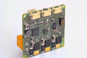
This year the r4.3 moteus controller was released for the first time. It lets you turn off the shelf hobby brushless motors into high performance servo actuators. The r4 series was a major revamp over the r3 used in the quad A0. It has CAN-FD, an STM32G4, and a higher input voltage of 34V.
It is still completely open source hardware and software on github: https://github.com/mjbots/moteus
I made a programming and test fixture for the controllers that runs a bunch of board validation steps, including calibrating a motor to make sure all the hardware works properly:
And I made a dynamometer with two controllers back to back and a physical torque transducer:
This let me both validate the firmware in an automated manner, but also resolve some defects that caused poor low torque performance.
You can now spin continuously in the primary position control mode, and the measured position can get arbitrarily far away from 0 as long as you only care about velocity and not the actual position.
There is a new control mode that lets you command upper and or lower bounds, within which only feedforward torque is applied.
And there is now optional compensation for magnetic saturation, which lets the controller report and use torque accurately even when the motor is nearing its peak torque.
Finally, the newest version is the r4.5, which is basically the same as the r4.3, but has manfuacturability improvements and supports input voltages up to 44V.
Next up is the qdd100 quasi direct drive actuator. I spent a lot of time educating myself at least a little about CNC machining, enough to design and manufacture a prototype all aluminum actuator. The first version was just a functional validation, then I did it again with a version optimized for weight and performance.
First is the one I made for functional verification (with an r3 moteus controller):
And here's the one that was optimized for weight and performance:
I then went and made a bunch of them:
I designed and released 3 different accessory boards in the past year. First is the fdcanusb:
Gotta love the PETG 3d printed case!
Next I did the power_dist board, which has a pre-charge function and 6x XT30 output connectors:
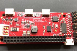
Finally, I did the pi3hat, which is a daughterboard for a Raspberry Pi 3 or 4. It has 4x CAN-FD buses, 1x low speed CAN bus, an IMU, and a voltage converter to power the Raspberry Pi from up to 34V.
I got to do some cool demos of individual components. First was measuring the ground truth torque of the qdd100 servo using a 1m long pole and a digital scale:
I also made a quick and dirty telepresence demonstration, where two qdd100s were linked together with a 2kHz rate control loop through a pi3hat. You could in software change the effective gear ratio, or even magnify torque without changing the rate of motion.
I've spent a lot of time iterating on the quad A1 lower foot and leg. I started out by switching the foot from a rubber end cap to a squash ball with foam cast inside:
And then worked through ~6 different iterations of material selection and lower leg and foot geometry as each one failed in some way. Can you spot the differences? ;)
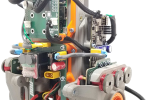
The chassis was completely redesigned so that it assembles in multiple pieces, and that all the important bits are kept nicely inside instead of strapped on to the top.
And I iterated on the cabling between the upper and lower leg, finally settling on some continuous motion plastic conduit, which I tested for 100,000 cycles.
The software changes aren't as amenable to summarization. If you're interested, watch the video, and check out all the links at: http://jpieper.com/2020/11/09/mjbots-november-2020-update/...
Read more »I think this is about as fast as I can achieve with the current gait controller. (for some reason hackaday isn't rendering the youtube inline for me reliably): youtube video
Here's a clip showing some walking outdoors, over tree roots, on gravel, and loose bricks.
Just another short video update. I've been working on making flight phases happen. I'm not sure my current approach is going to work long term, but I was able to get some stable video from it:
I've continued working on improving the gait speed, and am nearing the point of writing up the individual steps. For now, here's another very quick video update with the first trot at 2 m/s.
I've started on the process of increasing gait speed. I now have a gait engine that lets me parameterize the timings all the way out to flight phases and am working through the "niggly details" that come up when you actually try to use it. Here's a quick video showing some cherry picked nice walking from my first time trying it on the real robot:
I've tried lots of different approaches to standing up as the quad has evolved. The most recent variant used a low-torque non-IK sweep to get the legs into a position, where IK could be used to stand up. However, since the legs did their initial prepositioning with no IK, the legs would usually drag across the ground. On some surfaces with a lot of friction, they could get stuck and never reach the target position.
So, I updated it yet again, to add another phase. Now, the shoulders lift the legs well clear of the ground, then the lower two joints sweep into position, and then the IK sequence is used to stand up. The result is that now it can easily stand up even on EVA foam:
Create an account to leave a comment. Already have an account? Log In.
Have you considered using a neural network to optimize movement patterns? The current sense capability would be the ideal feedback mechanism.
I haven't, but it certainly is something that could be done!
In that case I would suggest using a neural networks to coordinate motion. If you can, also try using a genetic algorithm in a simulated environment (needs millions of trials to be useful) to optimize gaits, discover new efficient gaits and discover new movement strategies for obstacles.
I'm just catching up here after not having visited in a while. Nice to see the progress.
Unfortunately, like many projects of this nature, I don't have a great accounting of the total costs yet, and labor is a large portion of that. I am working to cost reduce the major components now so hopefully it will soon be more accessible.
The core compute right now is just a rpi3 b+.
I'm hoping to be able to get the individual actuators down to a sale price of around $500. Not hobby servo level, but for something that you can't get today at any price, not bad.
The rest of the robot is designed to be 3D printed modulo some belts and bearings, so with a Prusa you could get all the rest for basically free if your time doesn't count.
We're not actually that far apart (I'm in Cambridge, MA). If you're ever around let me know and I can show you the hardware I've got.
Fantastic! stellar work, excellent progress!
I have been challenged to build a set of robot "wings" for a performer, the wings must be able to retract into something like a backpack, open "dramatically" and "Flap" I designed a small working model using NEMA 17 and mostly re-enforced 3d printed parts. through many iterations I discovered using cables to actuate elbow, wrist, and hand equivalent joints works really well and dramatically reduces the weight at the end of the arm. At just over 2.5 feet between shoulder and elbow, elbow and wrist, wrist and hand, the span of the arm will be nearly 8 feet, then add another 2 feet for length of "fingertip" feathers, total apparent wingspan of nearly 20 feet is supposed to be "impressive" on stage.
I am at the stage where I need to build my first scale prototype. When I saw the MIT Cheetah, and it's shoulder mechanism I knew I had found what I needed to scale up. Then I ran across your channel.
Is there any way we could collaborate? Not looking for a hand out, but maybe like asked above, a BOM, and files so I can get boards made up and drive parts printed/machined. I'm a 30+ year senior software engineer, so no help needed in the programming department, but am not a natural mechanical engineer.
One other challenge is that each of my 2 wings is being required to have 9 DOF (2 DOF in wintip, wrist, elbow, and 3 DOF in the shoulder) On the positive side 4 of those DOF only have to produce a movement arc of just 27 degrees, and since this "robot" is for performance, aesthetics rapidity and fluidity of movement is way more important than accuracy.
You are certainly welcome to look at the BOM and designs that I used here, they are all public on github. https://github.com/mjbots/moteus/tree/master/hw/be8108_gearbox
and the controller is at: https://github.com/mjbots/moteus/tree/master/hw/controller
I will warn you that the iteration I'm using here in this video is very labor intensive to produce and not necessarily that cheap once you count the CNC machining. I probably spent 2 or 3 man days per actuator and I knew what I was designing. ;) I'm in the process of revving the design to something that I could just sell and am advanced in the prototyping phase. It will probably be 2 or 3 months before I have anything I could ship out though.
Thank you for the links! I completely understand about where you are in your iteration process. I've been revving on joint design and cable runs for several months now, and it'll take me several days just to assemble one joint and spar. I will get a joint assembled and attached to the test stand I built and make a mental note that I have got to take a "design for manufacturing" pass sometime soon.
Hey Josh, can you do a post on cost/how you built it, etc.?
Hi. Well, it is certainly still in the development stage, so "how I built it" is constantly evolving. You can follow more detailed updates at https://jpieper.com although I'll post bigger updates here when available.
This is very cool. After I get done(enough) with my rover, I'm interested in building a quadruped. You've made a huge amount of progress in a year. I'm curious, what material your 3D-printed parts are printed in ?
Everything on this machine was Prusament PETG printed on a MK3S.
Looking good! A lot accomplished in just one year, really. Can't imagine how long something like this would take me.
Thanks! I'm sure you know how it goes... no matter how much progress you make, there is always room for more!
Indeed I do - except few of my projects get even close to this far. Looking forward to where it goes next!
Thanks! I just posted a longer form update including a "one year in" status video.
Become a member to follow this project and never miss any updates

 Yannis Chatzikonstantinou
 Mike Moore
 Tim Wilkinson
 Darren V Levine
Hey Josh, I don't know if you are already aware but you made it to the "Video Friday" on IEEE Spectrum, Congrats !!!
https://spectrum.ieee.org/automaton/robotics/robotics-hardware/video-friday-aquanaut-robot