Close
0%
0%

All-In-One Gamma-Ray Spectrometer

More sensitive to gamma radiation than a Geiger counter with the added bonus of telling exactly what's inside your samples!

Similar projects worth following
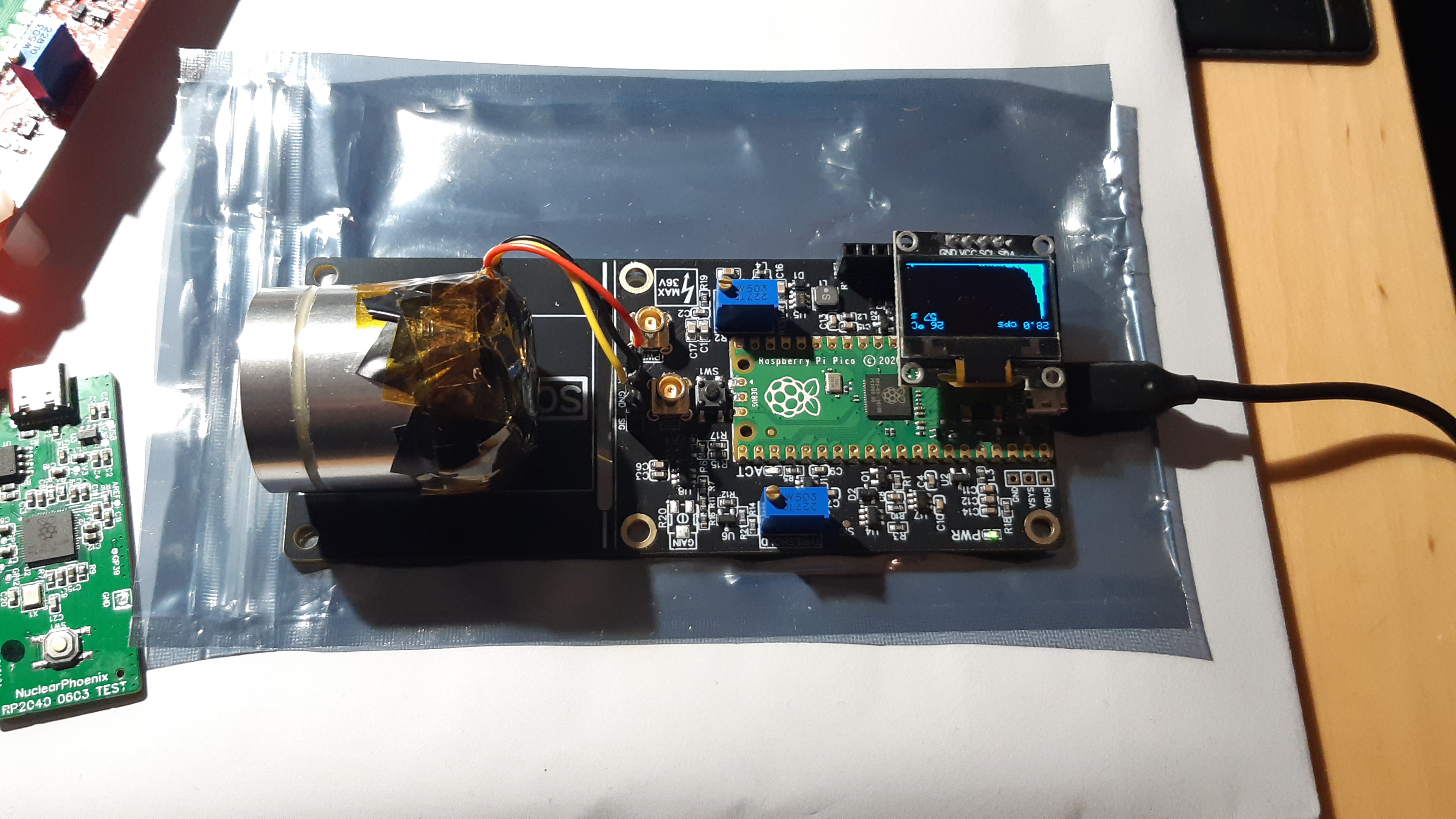
Using a small custom PCB with a Raspberry Pi Pico 2 microcontroller, a scintillator (typically NaI(Tl)) and a silicon photomultiplier (SiPM) you can build your own gamma spectrometer! The needed processing and multi-channel analyzer are all on-board so no external parts are needed, except something to look at the data (with a screen, obviously).

This detector uses a silicon photomultiplier (SiPM) instead of the usual photomultiplier tubes that are more common with these types of DIY projects. This means that the whole assembly is much smaller and also safer, because no high voltages are needed! Also in contrast to projects like theremino you don't strictly need a computer or even an external sound card -- everything is self-contained. You can do standalone measurements using only a USB power cable and save the spectra to the Pico's flash storage or connect to your PC via the Serial-over-USB connection.

Here are some of the most important key facts:

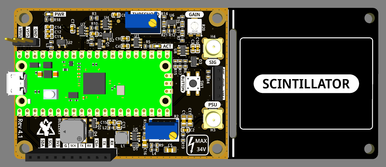
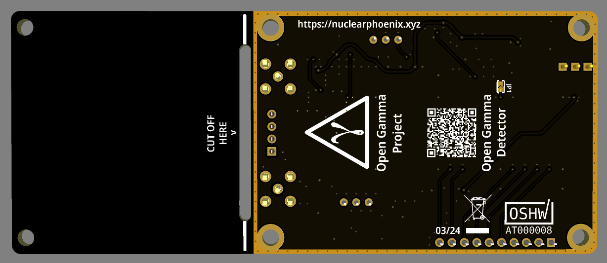
  • Compact design: Total size 120 x 50 mm. Approx. 70.5 x 50 mm area for electronics and additional 49.5 x 50 mm to mount a scintillator.
  • All-in-one: No external parts (e.g. sound card) required to record gamma spectra.
  • Standalone spectra recordings on built-in flash.
  • Easily programmable using drag-and-drop firmware files or the standard Arduino IDE.
  • Low-voltage device: No HV needed like with photomultiplier tubes.
  • Can use SiPMs in the voltage range of 27.5 V to 33.8 V.
  • 4096 ADC channels with built-in 3 V voltage reference.
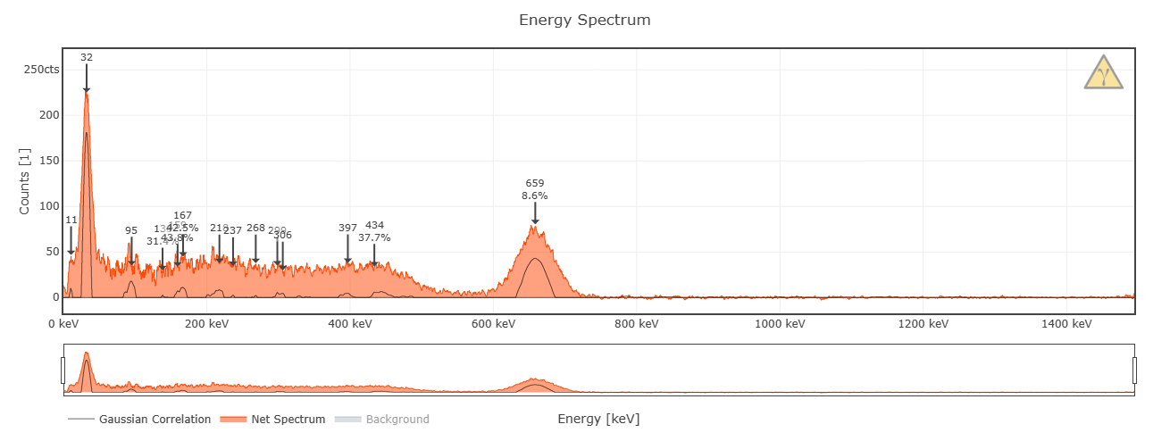
  • Energy resolution of up to 7% @ 662 keV possible; highly dependent on your SiPM/scintillator assembly.
  • Energy Mode: ~10 µs total dead time while measuring energy (default settings).
  • Geiger Mode: ~1 µs total dead time without energy measurements (default settings).
  • Low power consumption: ~15 mA @ 5 V with default firmware at normal background.
  • Built-in ticker (buzzer) for audible pulse count rate output.
  • Additional broken-out power pins and I2C, SPI and UART headers for custom parts (e.g. display, µSD card, etc.).
  • Simple OLED support out of the box (SSD1306 and SH110x).
  • Built-in True Random Number Generator.

More information can also be found in the GitHub repository...

Ok nice, but how do I get it?

  • DIY version: Download BOM and Gerber files or use Kitspace.
  • Buy a complete board: Head over to Tindie.
  • If you don't want to deal with all of that, feel free to contact me. Just send me an e-mail if you want and we'll figure something out.

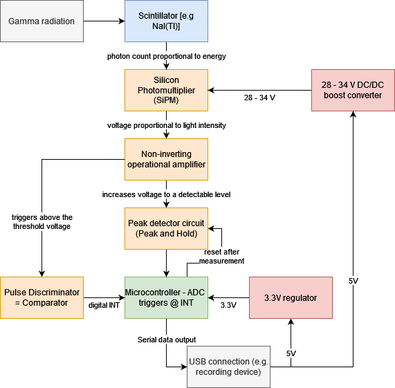
The principle of operation for the detector looks like this:

Read more »

BOM.csv

BOM for the detector board

application/vnd.ms-excel - 2.34 kB - 04/11/2023 at 21:03

Download

schematic.pdf

Schematic of the detector board

application/pdf - 136.30 kB - 04/11/2023 at 21:03

Preview

  • 1 × Raspberry Pi Pico 2 Microcontroller and heart of this detector
  • 1 × MicroFC-60035 SiPM The silicon photomultiplier used with the scintillator
  • 1 × Main detector PCB Production-ready gerber file in GitHub repo or Kitspace
  • 63 × Components main detector board See BOM for exact parts
  • 1 × Scintillator For example NaI(Tl)

View all 6 components

  • First Pico 2 Testing

    NuclearPhoenix08/29/2024 at 12:21 0 comments

    Just tested the new Pico 2 and the results are pretty amazing actually.

    The DNL issues, are obviously gone and with it the `cps correction` setting and some of the code in the event interrupt that had to handle the 4 error channels. Finally no more random peaks or missing channels in the spectrum!

    Due to this combined with the more powerful processor cores (and FPU), the total dead time reduced significantly, which is probably the biggest change. With the same settings both on the Pico 1 and Pico 2 at default settings the dead time in energy mode halved (!) from ~24µs to ~12µs. The dead time in Geiger mode actually reduced more than that, it only registered ~1µs of dead time on the Pico 2, while the Pico 1 had about 4µs. This is of course only the software-measured dead time, there will still be a bit of a constant overhead on top of all of that, that cannot be measured in software. It's pretty safe to assume that this hasn't changed too much between the revisions, so the relative decrease in dead time is very significant.

    The flash size is now triple that of the old version at 3 MB reserved for custom spectrum storage. This means you're able to record almost 3x the amount of spectra before running out of space, which is also huge.

    The cherry on top of all of this is that power efficiency went up too. Without any further changes, the detector now consumes a good 10% less power than before according to my testing. I will also investigate the new sleep/dormant modes of the RP2350 as soon as there is support for these.

    On a side note, I was able to overclock the Pico 2 to 250 MHz at the default 1V core voltage in the sketch, which is 25 MHz higher than with the Pico 2 (225 MHz). Therefore the `overclock` uf2 file will be clocked at 250 MHz from now on.

    All of the hardware and software files are up to date now for the Pico 2 and development will continue on the Pico 2 from now on. The new board revision 4.2 is unchanged from the old one besides the switch to the Pico 2 and an updated BOM position for the out-of-stock buzzer. I will update the post on my website to also reflect these results.

  • OpenDosimeter Project

    NuclearPhoenix08/21/2024 at 10:09 0 comments

    Hey there, I wanted to give a quick shout-out to an awesome new derivative project: The OpenDosimeter.

    If you're interested in dosimetry and radiation protection, go check them out! They're fully open-source and currently working hard to publish all the info and details needed to reproduce the device.

    https://github.com/OpenDosimeter/OpenDosimeter

  • Raspberry Pi Pico 2 and the Open Gamma Detector

    NuclearPhoenix08/10/2024 at 18:03 0 comments

    This article was originally posted on my homepage.

    The RP2040 microcontroller that is being used in the original Raspberry Pi Pico finally got a worthy successor: the RP2350! And with it Raspberry Pi released a new and improved version of the Pico, fittingly named the Raspberry Pi Pico 2. This is a big change for the Open Gamma Detector project, because it is going to substantially improve device speed and analog readout.

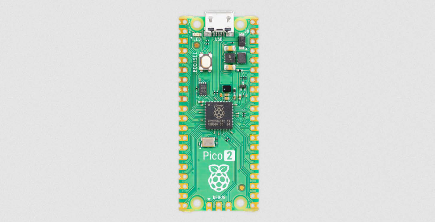
    The Raspberry Pi Pico 2, sourced from their Pico 2 product brief, see below.

    It's a drop-in replacement part for the original Pico, which means the pinout and sizing is the same as well as the software should be compatible with any changes, which is actually pretty huge. Ideally, the original Arduino IDE sketch can be reused without any modifications and the used pins on the device also remain the same.

    The new RP2350 boasts double the SRAM (520 KB), double the onboard flash (4 MB) and more powerful ARM Cortex-M33 cores. With it finally comes an FPU for faster floating point calculations and they actually fixed the DNL issues with the ADC boosting its performance by 0.5 ENOB! That means I can finally drop all of the botched code for the DNL issue compensation.

    The chip also adds a ton of new security features and optional RISC-V cores, which is very exciting to see, but not really relevant for the project. However, this is going to make the Pico 2 and RP2350 hugely more popular for all kinds of different IOT projects as soon as a wireless version comes out.

    What I'm excited to see as well is how the power draw changes for the whole device and if the switching regulator on the board changed, which could affect the noise levels on the board and most importantly, the noise at the ADC voltage reference. As far as I'm aware they also changed sleep and dormant modes, which should make them a lot more useful and more low-power compared to before. Anyways, the new core architecture will definitely change power draw, I'm sure. Let's hope it's for the better :D

    I have pre-ordered a Pico 2 now and I'm going to have a look at it as soon as it arrives. I'm certain it'll be a substantial upgrade in all of the relevant aspects to the project. I'll keep you updated!

    Check out the product brief from Raspberry Pi (PDF): https://datasheets.raspberrypi.com/pico/pico-2-product-brief.pdf

    Let me know what you think and how this is going to affect all kinds of different projects!

  • Rev 4.1: PCB Layout Update

    NuclearPhoenix03/29/2024 at 12:00 0 comments

    Did some work on the PCB and slightly updated the layout to make it all look better. The MCX connectors are now placed symmetrically on the board and the silk screen has had a heavy rework. On top of that I also added a grounded guard ring around the perimeter of the electronics section.

    The only other change is a different type of 22µF cap for bypassing, which now has an increased max voltage rating to better cope with DC bias. Other than that, everything remains the same.


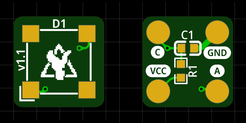
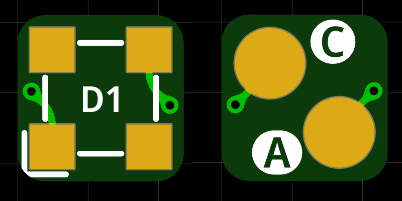
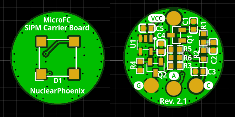
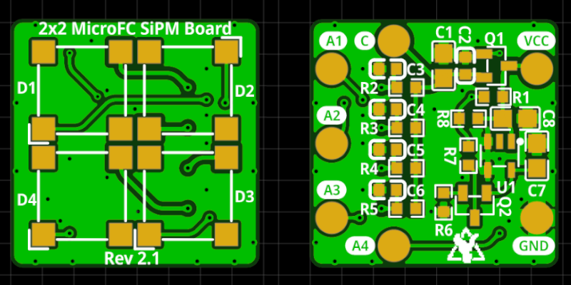
  • Updated SiPM Carrier Boards

    NuclearPhoenix02/16/2024 at 20:38 0 comments

    I reworked the SiPM carrier boards a little in terms of the layout and also used the opportunity to make a board for the 3mm MicroFC SiPM from onsemi. This will definitely come in handy if someone wants to play around with these little LYSO sticks (4x4x20mm or so). The files for the 3mm carrier board can be found on GitHub: https://github.com/OpenGammaProject/Tiny-3mm-MicroFC-Carrier-Board

    At 6x6mm, the board is slightly larger than a 4x4mm LYSO scintillator face, but it really couldn't be much smaller and it should work reasonably well regardless.

    Overall, the layout of all boards is now tidier and, above all, the important connections are all a lot more clear better marked. I also reduced the distance between the individual SiPMs a little in the 2x2 array. The circuit is otherwise identical.

    Here are the latest PCBs:

  • FW 4.2.0: Recording to flash

    NuclearPhoenix01/20/2024 at 18:36 0 comments

    This new update is a little bit bigger than the last one. One major new feature is the option to record spectra 100% locally on the device and save the data to the onboard flash to be retrieved at a later point. You can start a recording via the serial interface and then keep track of the status or stop it manually before it finishes. The data that has been gathered can be again printed to the serial interface at any point after that. For this I have also added a couple new commands relating to the filesystem on the Pico's 2MB flash.

    Because of these changes, your current settings and also the runtime stats of your device will be reset once you update! So be sure to note your settings beforehand and restore after the update if you changed anything.

    There are also some smaller changes like a change in default settings (see below) and better formatting for the general info and fs info screens over the serial interface.

    Full list of changes:

    • Flash space (total 2MB) on the Pico is now divided 50:50 between the onboard file system and the program space (1MB for the filesystem). This change will result in a reformat of existing devices.
    • Changed default settings for "subtract_baseline" and "cps_correction":
      • subtract_baseline = true
      • cps_correction = false
    • Improved formatting of "read info" and "read fs" info screens. Also removed some irrelevant data from the "read fs" screen.
    • Standalone recordings: Start and stop spectrum recordings via the serial interface, the rest will be handled by the device, you don't need an active connection in between and you can collect the data anytime after it finishes. The data will be saved to flash in a compatible JSON (NPESv2) format for viewing in other software. There is also a tiny indicator on the OLED for when the device is currently recording. The device will stop recording after the set time has run out and will autosave regularly (every 15 minutes) just in case of a power failure. New serial commands, pretty self-explanatory:
      • record start <time in minutes> <filename>
      • record stop
      • record status
    • New filesystem commands to view the contents of the data directory and of files that were previously recorded (NPESv2 JSON). There is also an additional command to remove files once you don't need the data anymore. The 1MB of flash on the Pico FS can hold a lot of spectrum files (get used and free sizes using "read fs" command). Commands:
      • read dir
      • read file <filename>
      • remove file <filename>


    I think these are really cool changes and finally start to show the power of this device. Neither do you need a sound card or any additional hardware to generate spectra, you don't even need a computer all the time anymore with the stock firmware. Set and forget. Set up your serial recording, and then come back hours later to "download" the data from the device. Just copy paste the contents into a file on your system and open it in Gamma MCA or a compatible program to view in all its glory. No additional computing needed. Doesn't matter what you do with your computer. Just be sure to keep the device powered ;)

    Enjoy!

  • FW 4.1.0: Button Changes

    NuclearPhoenix01/17/2024 at 22:31 0 comments

    With the latest firmware update I changed the way the buttons on the board work. In the past the BOOTSEL button on the Pico would always change the mode of the detector while the other button on the main board toggled the buzzer. This was always a bit odd to use honestly, especially when you have an OLED installed directly on the pin header next to the button.

    With firmware version 4.1.0 the large button on the main board now took over the BOOTSEL button's job and changes the mode as well. BOOTSEL on the Pico will from now on always reboot the device into bootloader mode for easier updating. You can change the mode by pressing shortly on the other more accesible and larger button. Long-pressing on the button will toggle the buzzer on or off.

    Also the display now reacts more quickly to reflect the change in mode by changing the screen after you pressed the button.

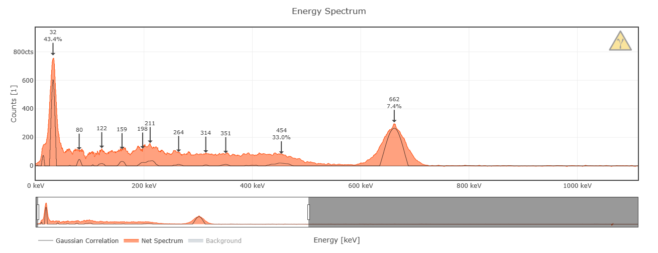
    And last but not least, today I managed to break my record for my personal best achieved energy resolution. I used the same mushroom sample (Cs-137) that I always used before and got 7.4% @ 662keV, nice!

    This is the configuration I used: 1x1" with 2x2 SiPMs like previously, but with a new detector main board.

    It's actually one of the pre-assembled boards, which interestingly slightly outperformed my hand-soldered version by almost half a percent lol

    Cheers!

  • Board Restock Rev 4

    NuclearPhoenix01/14/2024 at 00:01 0 comments

    Finally, after all the delays, the long awaited restock is here. You can once again get the fully pre-assembled main boards for the Open Gamma Detector on Tindie. EDIT: It's the new version of course, Rev 4! Here's a link to the listing:

    https://www.tindie.com/products/28827/

    This time they come in a nice black color with ENIG surface finish and all the necessary connectors pre-assembled too. As always you will have to get yourself a SiPM and scintillator as these are not included. The boards will need to be programmed at the first start as they don't come pre-loaded. If you're not sure how to do this, here is a quick guide (it's really easy): https://github.com/OpenGammaProject/Open-Gamma-Detector/tree/main/software#firmware-files

    Cheers!

  • (Small) Update

    NuclearPhoenix12/27/2023 at 21:29 0 comments

    Just a quick reminder that the project is not dead (and also a very tiny update) :D

    Regarding the Tindie restock, I'm sorry for the seemingly endless delays. The boards are currently in production and I'm expecting them to be in stock again ready for shipping by early to mid January.

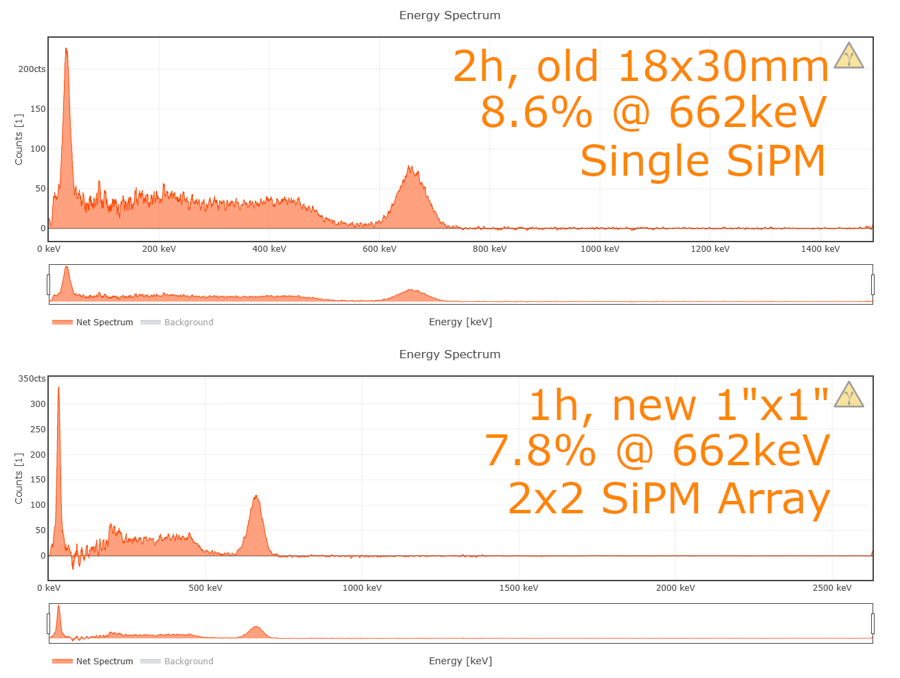
    To keep you interested and as a sort of small additional teaser, here is a comparison between my "old" scintillator with only a single SiPM that I used for all spectra up to this day and a brand-new 1x1" crystal with the 2x2 SiPM array:

    As you can see, the spectrum is a lot cleaner in total, the range is larger and the energy resolution is a lot better too. Keep in mind however, that this version costs at least around 100$ more than the "simpler" version, due to the added SiPMs and the larger, 4-layer array PCB.

    The larger scintillator comes with some additional benefits such as greater efficiency and therefore also higher count rate. You don't need one as large as this, though. 18x30mm is also a great size already pretty capable.

  • Notes about averaging (settings)

    NuclearPhoenix12/06/2023 at 21:41 2 comments

    I'm doing some last in-depth testing to optimize all the device settings for the best energy resolution possible and it looks like I found a much better suited setting for the ADC "averaging". In my case, I was able to get an improvement of about 1% just by switching this setting ("set averaging 2" from the default value 5). I've also just now changed the default value for averaging to 2 in the 4.x.x firmware to apply this improvement. If you already changed something in the settings, or you're using one of the older board revisions, you'll have to edit it manually.

    Give it a try, it might even work on older board revisions, but your mileage may vary. Nothing can break, so just feel free to experiment. If you're not sure, just reset the settings afterwards and you're fine.

View all 56 project logs

  • 1
    OPTIONAL: Solder SiPM carrier board components

    This is an optional step if you're using the carrier boards. If you're not and just soldering wires directly to the SiPM or doing it otherwise, skip this part. Note, however, that soldering wires to the SiPM itself is much harder than using the breakout board.

    You can choose to add the optional SMD components, to add some more power decoupling. This might help stability especially for longer cable lengths. If you're doing so, bridge the solder jumper and connect wires to VCC, GND and A(node) pads. If you're not using the SMD parts, solder directly to A(node) and C(athode) and the jumper remains open.

  • 2
    Couple SiPM with scintillator

    Center the SiPM on the scintillator crystal and put some silicon grease or other special coupling material between the two parts to optimize the optical coupling (and minimize reflections). This step is important!

  • 3
    Wrap scintillator assembly

    Use black electrical insulation tape or similar non-transparent material to wrap the whole assemby, but watch out for the cables, of course. This will reduce light passing to the SiPM to an absolute minimum, otherwise it won't work properly. You should use multiple layers of tape just to be sure.

    Tip: I'm using tightly-wrapped Kapton tape on the outer-most layer to avoid the insulation tape from getting too loose.

View all 8 instructions

Enjoy this project?

Share

Discussions

gabriel wrote 6 天前 point

hello, I am trying to create a cosmic ray detector by replacing the scintillator with a bc412. And I would like to know if it was possible to do as in his links

https://physicsopenlab.org/2019/12/21/muon-rate-monitoring/
https://physicsopenlab.org/2017/06/26/cosmic-ray-detection-with-gamma-spectrometer/

  Are you sure? yes | no

NuclearPhoenix wrote 4 天前 point

Hi there, I'll reply to you on your GitHub discussions post!

  Are you sure? yes | no

DGMP wrote 09/28/2024 at 12:46 point

Hello, thank you for your response. The pulse voltage from the PMT has no effect on the artifact. I suspect that these are muons, but what bothers me more are the periodic "dropouts" in the unaveraged native spectrum. These are evidently caused by the periodic discharge of the integration element, see: https://www.protheustrio.cz/error_spec.png. For spectrum analysis, I wanted to use the InterSpec software, but unfortunately, the spectrum is unanalysable. I might be wrong, and the missing signal parts could be caused by another software interruption.

  Are you sure? yes | no

NuclearPhoenix wrote 09/30/2024 at 11:45 point
Oh yeah I know about that :/

I'm not totally sure where that comes from either, but I'm guessing it's mainly just the flawed ADC on the RP2040. When I did my Pico 2 testing, this effect was a lot less noticable than with the old Pico.

  Are you sure? yes | no

mihai.cuciuc wrote 09/30/2024 at 15:54 point

Hi! Sorry to barge in on your discussion but I have very similar periodic dropouts in the spectrum with completely different hardware and in my case it's also the ADC on the microcontroller I'm using that's causing it. I don't know about the Pico2 but I think most MCU ADCs will have this sort of issues. In addition to my SAML21 tried an STM32 and it had similar behaviour. What I ended up doing on my project was to cheat a bit and compensate for this behaviour with some randomness. If you're interested here's what I did: 

https://hackaday.io/project/194457-pomelo-gamma-spectroscopy-module/log/229293-adc-calibration

You can apply a simpler version of this algorithm on your spectrum before you feed it into InterSpec, but you will need to know what your ADC produces when you expect to see a uniform histogram. Let me know if you want me to look up some of my ROOT scripts on this.

  Are you sure? yes | no

DGMP wrote 10/01/2024 at 14:08 point

Hello, thank you for the information regarding weighted dithering. In my case, it always concerns empty bins 3, 11, 19, and so on. I applied weighted dithering for the two surrounding correct bins to fill in the empty ones. Although it’s not a completely ideal solution, it’s sufficient for my purposes and gives a much better result compared to the moving average, which I also tried. I’m attaching an example of how the spectrum looks without dithering and with dithering.

https://www.protheustrio.cz/dithering.mp4

https://www.protheustrio.cz/no_dithering.mp4

Best regards.

  Are you sure? yes | no

mihai.cuciuc wrote 10/06/2024 at 08:13 point

Wow, you dithered spectrum looks really nice! Congrats! I guess InterSpec is much happier with it now, right?

  Are you sure? yes | no

DGMP wrote 10/07/2024 at 18:02 point

Hello, yes, InterSpec already processes the data, but I'm not very satisfied with it, I don't like the resolution, I'm attaching the output from InterSpec, it's a 120-minute exposure of a LySo scintillator with a lead shield without reading the background.

https://www.protheustrio.cz/Lu176.html

  Are you sure? yes | no

DGMP wrote 09/22/2024 at 14:48 point

Hello, thank you in advance for your excellent project! I have connected the board to a Nal(TI) 3"x 3" PMT, and I limited the pulses from the PMT to +1.6V using a resistor divider after inversion. I am attaching a snapshot of the setup: https://www.protheustrio.cz/Scinti.jpg. For now, I am using an Rpi Pico, but I am planning to switch to the Rpi Pico2. Everything works perfectly; I am only struggling with an artifact on the photopeak around 1500keV. For interest, I am attaching the LYSO scintillator spectrum after 10 hours in lead shielding: https://www.protheustrio.cz/Lu.html

  Are you sure? yes | no

NuclearPhoenix wrote 09/23/2024 at 09:24 point

Hi there, that's very cool. Indeed I think you might be the first one to successfully use the board with a PMT and it looks like it works perfectly! The artifact is very likely related to the voltage clipping at the upper end of the range like mentioned here: https://github.com/OpenGammaProject/Open-Gamma-Detector/blob/main/REFERENCE.md#there-is-always-a-peak-near-adc-channel-4095

You can lower the input signal voltage and look how that changes the peaks, or honestly just ignore it because you know it's just garbage :^)

  Are you sure? yes | no

ilkaydemirhan wrote 03/29/2024 at 18:30 point

Hi,

I interested this project. I want to buy a complete board but it looks out of stock in Tindie. Is there anywhere else I can buy it? Will it be back in stock? Does anyone have knowledge about this?

  Are you sure? yes | no

NuclearPhoenix wrote 03/29/2024 at 19:04 point

Hi there, you're correct it's currently out of stock and I'm not sure if I will do a restock to be honest. Depends on the demand of you guys, so please join the waitlist in the mean time if you're still interested.

You can also always go to a pcb manufacturer yourself and go through the steps of getting them manufactured for yourself. All the files for that should be on GitHub. Some cheap ones include JLCPCB and Elecrow. PCBWay too, but I think they're website is less user friendly. Hope that helps!

  Are you sure? yes | no

ilkaydemirhan wrote 03/29/2024 at 21:18 point

Hi Dear, thank you very much for quick reply. I joined waitlist. In the meantime, I will look at all the files on GitHub and try to do it myself.

Best regards.

  Are you sure? yes | no

ulrich.uw.weber wrote 03/03/2024 at 17:19 point

Hi,

first of all I want to thank you for your effort, kindness and your patience ;). I ordered (unfortunately) Rev.3 boards at first via kitspace and had some issues to get the raspberry running. I ordered Rev.4 boards now and wait for them to arrive. Neither the readily compiled uf2 nor the compiled ino (Rev.4 now) worked in the beginning. Setting up the Arduino IDE on a newly installed laptop got it working partly. I could see the output in a serial window, but neither one of my displays (SSH_1306 or SH_1106) did work. I compiled the ino several times with different I2C addresses (3C vs 3D) and both displays in true/false but nothing helped. Finally I started playing around with the pico using the serial console and found the "set display" command. After switching it to "on", the display worked perfectly well. Maybe you could mention in the readme.md for the software at git, that the display default is "off". Maybe that saves someones time and nerves ;). Please consider this not as a critic but as a suggestion.

Best regards and greetings to Austria 

Uli

  Are you sure? yes | no

NuclearPhoenix wrote 03/04/2024 at 11:36 point

Really sorry for the confusion. I thought I put a note there about that, but apparently I deleted it at some point. I'll write something about it in the README again, thanks!

  Are you sure? yes | no

John Beale wrote 12/09/2023 at 00:18 point

I am very interested in this project. I already have a few "pocket" size commercial gamma spectrometers, but I am looking for higher sensitivity (more counts for a given uSv/h rate). I gather finding the scintillator and SiPM is up to each experimenter. I see an eval board with the Onsemi ONSEMI MICROFJ-SMTPA-60035-GEVB is available (Newark 82AC2991 ), would this work? Is there any recommended type of scintillator, and source for same? I'm familiar with electronics generally but the scintillator area seems like a specialty all to itself, plus matching it optically and mechanically to the detector. I live in a humid area; is NaI(Tl) so hygroscopic it's going to turn into a puddle before I can even use it? I don't care so much about compact size, but I'm looking to maximize my (count rate per dollar) quotient

  Are you sure? yes | no

NuclearPhoenix wrote 12/15/2023 at 11:52 point

Hey, sorry for the late reply, I don't get notifications for comments unfortunately.

I'm pretty sure that board you mentioned would work. The one thing you have to keep in mind is that you need to get a good bond between the scintillator on the SiPM. So I don't know if the solder joints actually rise above the face of the SiPM. That would be very bad, because you won't get a flat bond between the two. I don't know about that for sure, so you might have to just figure it out.

As for the scintillator, I definitely recommend you get a NaI(Tl) crystal. As an example, you can get one from here cheaply: https://www.ost-photonics.com/product/diameter-1-inch-x-1-inch-naitl-scintillator/
You won't get a particularly good energy resolution with this one and just a single SiPM, but you'll definitely get a pretty high sensitivity with this large a scintillator. All NaI scintillators that you can buy come hermetically sealed, so don't worry about humidity.

  Are you sure? yes | no

John Beale wrote 12/15/2023 at 16:53 point

Thanks, yes I see. I'd rather not be grinding down header pins right next to a fragile optical sensor, and I see you have several SiPM board designs online, so I'm doing an OSHPark order. Looks like $30 on ebay buys a small NaI(Tl) crystal that comes inside a PMT assy ( Hamamatsu R7400U ). Photos suggest it could be hacked open, if one was prepared to deal directly with the bare crystal.

  Are you sure? yes | no

John Beale wrote 12/15/2023 at 17:21 point

Thanks for the ost-photonics link. I see they have 1"x2" also, would that be expected to give you double the count rate as 1"x1" ?

  Are you sure? yes | no

Robert wrote 12/16/2023 at 06:52 point

To answer John's last question, I am using a 1"x2" scintillator from Ost Photonics with my Open Gamma Detector, coupled to 2x2 SiPM array. I roughly get a 50% increase in background count rate compared to a 1"x1" scintillator, but the sensitivity at higher energies is significantly improved. Also, with the SiPM array, energy resolution improved to around 7.5% FWHM.

  Are you sure? yes | no

NuclearPhoenix wrote 12/16/2023 at 11:26 point

Yeah like @Robert already mentioned, it's not a linear increase in count rate per volume, but you'll still get noticeably more than with a 1" x 1". Haven't done any testing on that myself, but his estimate sounds right.

  Are you sure? yes | no

pnrsl wrote 10/27/2023 at 10:22 point

Hello,

We  pluged in the Raspberry Pi Pico via the micro-USB connection. A file manager window poped up. we draged and droped the opengamma_pico_3.5.1.uf2 file that we downloaded into this directory, but we couldent see any result. After that we thought that we can solve this problem by using Arduino ide (our aim is not changing any thing in code ), but we obsorved that there is problem in helper.h library. 

Thank you in advance.

  Are you sure? yes | no

NuclearPhoenix wrote 10/27/2023 at 11:56 point

Hello, I'm pretty sure you have contacted me now with the same problem for a couple of months. I have replied to each and every one of your messages (on GitHub, multiple times via e-mail, ...) with some suggestions and questions and you did not get back to me every single time. Instead you keep posting the same questions over and over. Sorry, but this is the last time I will reply to you. After that, good luck.

Ok, so. Can you specify "you couldn't see results"? What do you mean? No display? No serial connection? Did the power LED not light up?

To get the sketch to compile in the Arduino IDE you need to download the entire directory (or even better the whole repository) from GitHub, which also contains the helper header file. Please post the error message if that didn't resolve the issue.

Hope that finally helps.

  Are you sure? yes | no

ijcarlson07 wrote 08/09/2023 at 19:46 point

Hi! I am thinking about build your project, but I would like to be able to display the data on a Raspberry Pi touch screen, Would I need a whole new raspberry Pi 4 to do this? I would like to make this portable.

  Are you sure? yes | no

NuclearPhoenix wrote 08/10/2023 at 10:16 point

It really depends on the touch screen. You need one that works via I2C or SPI and has library support for the Pico/Arduino. Honestly, I'd just get some kind of breakout touch screen from Adafruit or something. They have great documentation and almost always some kind of library support for Arduino.

  Are you sure? yes | no

miles wrote 08/05/2023 at 21:58 point

Hi! I recently built your project, however when I got to the actual data collection I noticed there were a few problems in my spectra, the source of which I have been able to track. My setup uses a 1" by 1" cesium iodide crystal as well as the suggested MICROFC-60035-SMT-TR1 SiPM (and the active carrier board). One point where it deviates from the suggested design is 3' of BNC cables connecting the probe to the driver (all shielded and grounded). The actual problem that I have run into is when I go to collect background data the overwhelming majority of pulses are recorded at 209 (5,000 counts in 20min) as well as a second lesser spike at 217 of 1500, this is with 4" of lead and cement shielding. The average is 50.3 +- 200 cps. I have tried adjusting the gain with limited success. Do you know what could be the cause of this problem?

Thanks

  Are you sure? yes | no

NuclearPhoenix wrote 08/05/2023 at 22:34 point

Hi! Does the spectrum otherwise look okay? It sounds like a noise issue to me. DId you try changing the discriminator threshold?

  Are you sure? yes | no

miles wrote 08/05/2023 at 23:08 point

I originally adjusted it quite a bit to get the estimated 10-50cps range (outside shielding). Other than the unusual spikes the spectrum looks about as expected. 

  Are you sure? yes | no

NuclearPhoenix wrote 08/06/2023 at 12:32 point

Huh, that's weird. If that doesn't help, maybe it's somehow an issue with the BNCs like Sebastian mentioned. An easy way to debug if it's a cable issue is to try and use some ordinary, short copper wires to connect directly to the SiPM board. If that helps, you know it's something to do with your BNC cables.

  Are you sure? yes | no

Sebastian D'Hyon wrote 08/06/2023 at 06:45 point

That is a large deviation for spikes.

Are you using Na or Ti doped crystal? The C series Onsemi sensors are better suited for Na doped crystals, but should still work for Ti, so this probably isn't the issue.

Also I found that a 1" crystal is better suited with a 2x2 array due to the large size.

I would perhaps check if you have any light leaks in your assembly. Also, if you're using BNC I would check to see if you're only grounding the shield at board side, it could be a ground loop issue?

  Are you sure? yes | no

gasel86895 wrote 04/22/2023 at 17:31 point

Hi, this is very interesting. I would like to understand your thinking in the preamp design and why a transimpediance preamp design wasn't used.

  Are you sure? yes | no

NuclearPhoenix wrote 04/22/2023 at 21:00 point

Hi, yeah I get this question a lot. In a nutshell, it boils down to saving cost and complexity. You could do that of course and it might (?) improve energy res by a couple %, but you'll pay that with multiple times the cost and complexity. That's just not worth it for this kind of device IMO.

  Are you sure? yes | no

NuclearPhoenix wrote 04/23/2023 at 10:53 point

Just added a new FAQ section on the design/cost thing if you want a more detailed explanation: https://github.com/OpenGammaProject/Open-Gamma-Detector/blob/main/REFERENCE.md#why-dont-you-use-a-tia-or-csp-or-change-x-or-y

  Are you sure? yes | no

Sebastian D'Hyon wrote 04/20/2023 at 08:06 point

Hey, awesome project!

Any chance for a .step file for the PCBs? Would like to do some modelling for a custom case and shielding. I'll share whatever I make.

  Are you sure? yes | no

NuclearPhoenix wrote 04/20/2023 at 08:55 point

Hm, I don't think EasyEDA supports STEP exports. But I can give you .mtl and .obj files. Let me know if that works too!

  Are you sure? yes | no

Sebastian D'Hyon wrote 04/20/2023 at 10:11 point

This will work!

  Are you sure? yes | no

NuclearPhoenix wrote 04/20/2023 at 11:46 point

Just uploaded it to GitHub! https://github.com/OpenGammaProject/Open-Gamma-Detector/tree/main/enclosure/3D

  Are you sure? yes | no

sukhjinder564 wrote 03/31/2023 at 16:27 point

Hi, I am trying to flash my pico with the firmware you have provided, but it does not reboot once I drag the .uf2 file over in Windows. I tested a simple LED blink program using MicroPython to confirm that I can communicate and run something on the Pico. Do you have any idea what may be occuring?

  Are you sure? yes | no

NuclearPhoenix wrote 04/02/2023 at 11:53 point

Hm, that's weird. So the micropython sketch works fine?

What UF2 file are you using specifically?

I'm not sure what could possible be causing this, especially since you had success with micropython. Did you flash the micropython firmware previously and then upload scripts via thonny or something like that?

  Are you sure? yes | no

sukhjinder564 wrote 04/03/2023 at 17:18 point

I was able to flash the board after compiling the sketch on your git, but the provided .uf2 file does not work. Not sure why. I had been using thonny previously. 

I have been noticing that the noise on the SiPM comes in at high energies (~600 keV!) - I cannot see the Cs137 peak well and cannot see the 511 peak in Na22. The assembly is light-tight, and I have adjusted the gain as well. Do I need to have a 50 ohm resistor on the anode? I currently have four wires soldered directly to the SiPM that are being fed into the PCB.

  Are you sure? yes | no

NuclearPhoenix wrote 04/04/2023 at 10:34 point

Okay, that is very weird. Especially since all the Arduino upload does is generate a UF2 file, reset the device and copy the UF2 to the device folder. So it's basically the same.

Anyways, did you calibrate the device with some known isotopes? Because the raw output you get is just the ADC channels, i.e. bins.

Are you using the SiPM breakout board? And what cables do you have connected? You only need 3 at max, one for anode, cathode and a ground.

You don't need any additional resistors.

Can you maybe send me a PM with one of your spectra please, where I can see the noise peak?

  Are you sure? yes | no

sukhjindersingh564 wrote 01/25/2023 at 19:37 point

Hi, this is a very interesting project.

I am having trouble finding any of the C-Series SiPMs in stock, do you think one of the J-Series SiPMs is a good alternative? For example the MICROFJ-60035-TSV-TR1?

Thanks!

  Are you sure? yes | no

NuclearPhoenix wrote 01/27/2023 at 11:28 point

Hi, just had a quick look at it and it seems like it would work. They look mostly similar to the C-Series SiPMs.

Another alternative for you would be the Broadcom Avago AFBR-S4N66C013.

I also have a breakout board for this: https://github.com/OpenGammaProject/AFBR-SiPM-Carrier-Board

  Are you sure? yes | no

Fabian Meier wrote 12/19/2022 at 09:01 point

Need some pointers in getting started with board from Makerfabs.

Hi NuclearPhoenix, great project - thank you very much for your time and effort.
I ordered a board from Makerfabs. I don't get any connection via USB - I don't see a serial port nor a USB flash drive (also by holding down the BOOT key). The LED ACT on the analog board is always on, I have about 20V on the PWR pin for the detector. It seems the RPI Pico board is not responding as it should. Did Makerfabs already download the Gamma Ray firmeware to the RPI? Thank you!

  Are you sure? yes | no

NuclearPhoenix wrote 12/19/2022 at 11:52 point

Hi,

there is no firmware pre-flashed. It should pop up as an external drive as soon as you first plugged it in. Very weird that it doesn't react at all! If you press and hold the BOOTSEL key _while_ plugging it into the USB, your computer also doesn't recognize any external drive? Do you have any other Pico at hand to test it on that one, just to exclude any issues related with your computer?

If not, please hit me up with an email and maybe attach some photos of the board too.

  Are you sure? yes | no

Erhannis wrote 12/16/2022 at 22:04 point

Questions!  You mention it being sensitive to EMI - is that just the main board, or the SIPM, as well?  Could you put the main board in a box and wrap it in foil, and have the SIPM on an external cable?  Would having a long cable (maybe a meter?) between the main board and the SIPM introduce a lot of noise or other problems?  Thanks!

  Are you sure? yes | no

NuclearPhoenix wrote 12/17/2022 at 13:24 point

It's the main board and the SiPM as well. I wouldn't recommend long cables at all, except for shielded coaxial cables. Best case would be everything inside a grounded thin aluminium enclosure with as short cables as possible to the SiPM.

  Are you sure? yes | no

Chris wrote 09/15/2022 at 20:12 point

Hello NuclearPhoenix,
can I also connect a PMT with a NaI(Tl) scintillator? I will use a HV Splitter, so that only the pulse signal after the splitter can reach the signal input circuitry of your board.

So I mean can I replace your SiPM detector board with a PMT detector? If yes what will I have to care about?

  Are you sure? yes | no

NuclearPhoenix wrote 09/15/2022 at 20:51 point

Hi, if you manage to supply the detector board with positive (!) pulses from your PMT you could get this to work. I don't know the voltage (signal) levels you're dealing with in your setup of course, so definitely watch out to not kill the preamp by overvoltage. Absolute maximum rating is -0.5 to 3.8 V in this case, preferably 0 to 1.6 V.

Definitely let me know if you manage to get some results, sounds really interesting!

  Are you sure? yes | no

Chris wrote 09/15/2022 at 21:06 point

Hi, I had ordered the PMT and NaI(Tl) scintillator crystal from different sources. The HV power supply I am using can be regulated from DC to 1000V with a maximum of 2 mA. That should be enough to drive the PMT. It has a power divider at its end and needs only a HV supply of appr. 850 V for working. After that there will be a HV/signal splitter which separates the HV and the signals. I have to measure the signal level if I received both items and build together. I am happy to write the results here in your blog. Your board is already here (orderered from Makerfabs). They are really quick in shipping. After 7 days I received the board completey really professional build. Thumbs up!

  Are you sure? yes | no

Chris wrote 10/23/2022 at 16:30 point

Hi, now I got my NaI(Tl) Scintillator crystal and build als parts together for my PMT sensor. After calibration of my signal inverter amplifier (build in a shielded Al-housing with high qualitiy BNC connectors from huber & suhner) I played a while around with the trimmer settings till my scop says that the voltage peaks amplitudes are in the range of 400 mV to 1,9 Volts. Yess it runs!

Your Open Gamma Detector is showing cps rates... I have to reduce the PMT Voltage from 850  to 760 Volts, because NaI brings much more higher pulses as Bicron 412 Scintallators. That is impressive. The whole system seems to work now and I am playing with your Gamma MCA...

Fantastic project! Respect!

If you want I can post the hardware mods so that other interested readers can adapt it to their own PMT.

  Are you sure? yes | no

NuclearPhoenix wrote 10/23/2022 at 17:48 point

Awesome! Don't forget to turn down the preamp gain on the board if your input signals are already at 100s of mV, but best not all the way. You could also desolder one of the 10 Ohms feedback resistors next to the preamp to get a gain of 1 and fully turn down the potentiometer. This way you'll probably get the best range for your setup. Signals could then start at ~100 mV up to the 1.6 V max.

Please feel free to post more info on your hardware, I'm interested ;)

  Are you sure? yes | no

Jesse wrote 09/03/2022 at 13:27 point

Awesome little project, I work at a university in the nuclear engineering department but am not very strong in the EE area. I ordered one of the boards but I'm still looking for a SiPM chip. It appears all possible sources are back ordered. Would the evaluation board (MICROFC-SMTPA-60035-GEVB) be an appropriate substitute, it looks like these are still available? 

Thank you and keep up the great work!

  Are you sure? yes | no

NuclearPhoenix wrote 09/03/2022 at 15:59 point

Hi there, thanks for your comment and encouragement ;)

The MICROFC-SMTPA-60035-GEVB should work no problem, you'll only need pins 1 and 3 on it. The only issue might be the pin headers, though. I can't really tell from the images, but on the front side the solder joints could be actually higher than the SiPM itself so you wouldn't get any optical contact with the scintillator. Other than that you need to get it light-tight somehow and you're ready to go. Honestly, I would just desolder them and save some headache this way.

  Are you sure? yes | no

Jesse wrote 09/03/2022 at 16:37 point

Thanks for the reply. I hadn't considered some of those issues before. 

If I was to go with the AFBR-S4N66C013 as an alternative the spec sheets shows several more leads than the MICROFC-60035-SMT.

The spec sheets says "All cathode balls (C_1 to C_6) are connected together. All anodes (A_1 and A_2) are connected together. Unlabeled balls are floating, preferred electrical connection to cathode voltage. "

Would I only need to solder one wire to a single anode ball (ground), one wire to a cathode ball (power) and one wire to a single floating ball (signal)? Sorry for my ignorance on this. 

Also, would the MICROFC-10010-SMT-TR1 be another alternative?

Thank You!

  Are you sure? yes | no

NuclearPhoenix wrote 09/03/2022 at 17:32 point

Yes, the AFBR-S4N66C013 has a completely different package which is much harder to solder! According to the datasheet the anode must be connected to the SiPM voltage and the cathode to the signal pin. You don't need ground here. I haven't found any eval boards for this kind of SiPM, that would definitely come in handy!

I would advise against the MICROFC-10010-SMT-TR1 as the general photon detection efficiency is much smaller (and the size too of course). In addition to that its gain is also smaller by an order of magnitude. Maybe you could get the 35 µm version of the 1 mm SiPM, that might work again.

  Are you sure? yes | no

Jesse wrote 09/03/2022 at 21:05 point

Awesome, thanks for the help. I'll let you know how it goes. I'll probably stick with the MICROFC-60035-SMT and wait for stock to come in.

  Are you sure? yes | no

hathawayresearch.george wrote 08/29/2022 at 14:36 point

Will someone offering a complete "OEM" package including SiPM & Scint for those willing (like me) to pay but don't have the time to build?

George Hathaway (george@hathawayresearch.com)

  Are you sure? yes | no

NuclearPhoenix wrote 08/30/2022 at 09:11 point

Hi there George, I can only speak for myself, but currently I don't have the capacity to offer complete kits. I've started with the main detector board now and if there's enough interest, I'll also offer the SiPM on its little carrier board too.

  Are you sure? yes | no

hathawayresearch.george wrote 08/30/2022 at 16:26 point

Thanks for the reply. Hope someone might pick this (full OEM) up someday. Such a cool project.

  Are you sure? yes | no

ysyangsongzz wrote 07/19/2022 at 09:44 point

I will try the DIY project ,I hope you provide new information.

  Are you sure? yes | no

ysyangsongzz wrote 07/18/2022 at 09:47 point

Your answer:The energy resolution is at about 15% @ 300 keV, very highly dependent on the scintillator crystal of course and your whole SiPM/crystal assembly. In fact, I'm not even sure 15% is the best, it's just what I achieve with my simple used scintillator. I couldn't test it with Cs-137 at the nominal 600 keV yet.

My question:This resolution is a little poor. The resolution of normal Nai scintillator spectrometer can reach 7%~8%. Can the energy resolution be improved by changing Nai and increasing the number of SIPM?At present, this product cannot measure Cs137?

  Are you sure? yes | no

NuclearPhoenix wrote 07/18/2022 at 15:23 point

Like I said, I bought my scintillator used so I don't know the energy resolution 100% for sure. You will probably have a better resolution with a brand-new crystal from a reputable manufacturer. The detector can measure Cs-137, of course! I simply haven't come around to measuring it since I don't have it  at home currently ;)

In fact if you can get a great mount with the new SiPM carrier board, you will surely get an even better resolution. By the way, most of the cheaper commercial spectrometers have an energy resolution of up to 12 - 13% so that's not too far off. However, that's measured at the Cs-137 662 keV line so you can't compare it 1:1.

  Are you sure? yes | no

Similar Projects

Does this project spark your interest?

Become a member to follow this project and never miss any updates