-
keeping track of your weather station sensors into homeAssistant
03/12/2024 at 16:56 • 0 commentsRight now we have intgrated our weather station with thingspeak and WindyApp.
But as we do have Home Assistant installed why not keeping track of our weather station directly into HASS ?
Doing this will allow us to use the full power of automations provided by HASS.
Such as : temperature is high and humidity is low ==> increase watering time of our gardens.
So what we will have to do is :
- modify our ESP32 GTW0 code to publish sensors values to MQTT broker
- configure HASS to subscribe to our weather station sensors.
As an example we will add temperature and humidity to HASS.
GTW0 code update
Modification of the code will be very simple as all the "difficult" job of connecting to MQTT broker is already handled to receive "commands" from HASS.
So we are already connected to our broker!
To send MQTT messages to our broker we just have to define "topics" for our messages and publish them with the sensor value into the payload.
  if ((((millis() - timeOut) > sendTimeTimeOut) && (hasRtcTime)) || (gtwStatus == sleeping))  //if (hasReceivedSensors) ThingSpeakPost();
  {
    hasReceivedSensors = true;
    for (int i = 1; i < nbGtw + 1; i++) hasReceivedSensors = hasReceivedSensors & gtwHasSentStatus[i];
    if (hasReceivedSensors) {
      ThingSpeakPost();

#ifdef USE_MQTT
      //send sensors values temperature and humidity to MQTT broker

      //convert float into string for "MQTT pubSub"
      char buffer[8];
      double temp = sensorValues[1][0][0];
      String s = dtostrf(temp, 5, 2, buffer);
      client.publish("sensorValue/temperature", buffer);

      temp = sensorValues[1][1][0];
      s = dtostrf(temp, 5, 2, buffer);
      client.publish("sensorValue/humidity", buffer);
#endif

#ifdef DEBUG_TELNET
In this example we do send temperature and humidity values after convertion from float to char array.
- the topic for temperature will be "sensorValue/temperature"
- while the topic for humidity will be "sensorValue/humidity "
These lines of code should be present only if using MQTT... thus we have the conditional compilation #ifdef USE_MQTT.
And that's it. Compile and run! now temperature and humidity will be published to the MQTT broker.
Subscribe to temperature and humidity sensors in HomeAssistant
We will have to add "sensors" into HASS. This can be done very easily into our configuration.yaml file.
Syntax is explained into the offcial documentation and couldn't be more simple !
Thus for temperature and humidity we add 6 lines into the configuration.yaml at the end of the "MQTT" block
sensor:
    - name: "Temperature"
      state_topic: "sensorValue/temperature"

    - name: "Humidity"
      state_topic: "sensorValue/humidity"
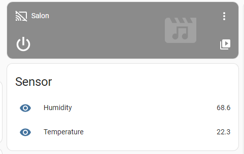
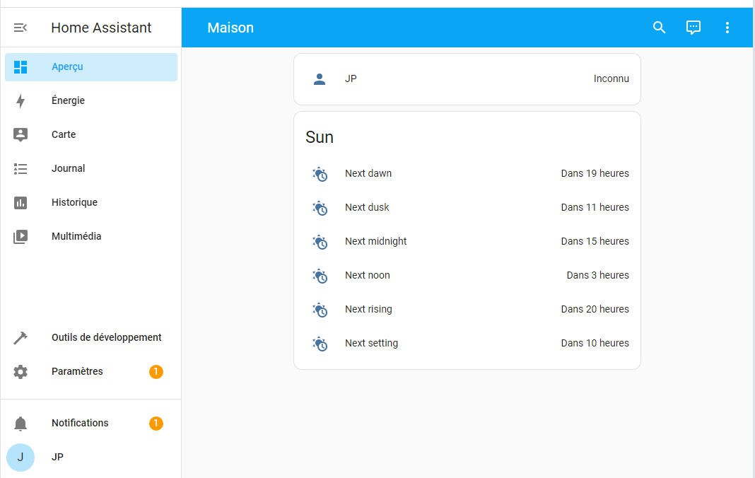
save the file, relaunch HASS and you have now access to your sensors in the main screen
Bingo, you can do what you want with these new sensors !
-
A new board for Rezodo : 6 irrigation valves + ESPNow
04/28/2023 at 14:29 • 0 commentsJust an illustration of Rezodo flexibility: here is another board fully compatible with Rezodo network:
- 6 valves
- 2 moistures sensors
- ESPNow (but no Lora!)
The PCB is available on shared Project at PCBWay: https://www.pcbway.com/project/shareproject/Rezodo_Long_Range_irrigation_and_weather_station_ESPNow_module_with_6_valves_5eba33d4.html
And thank you PCBWay for sponsoring this board !
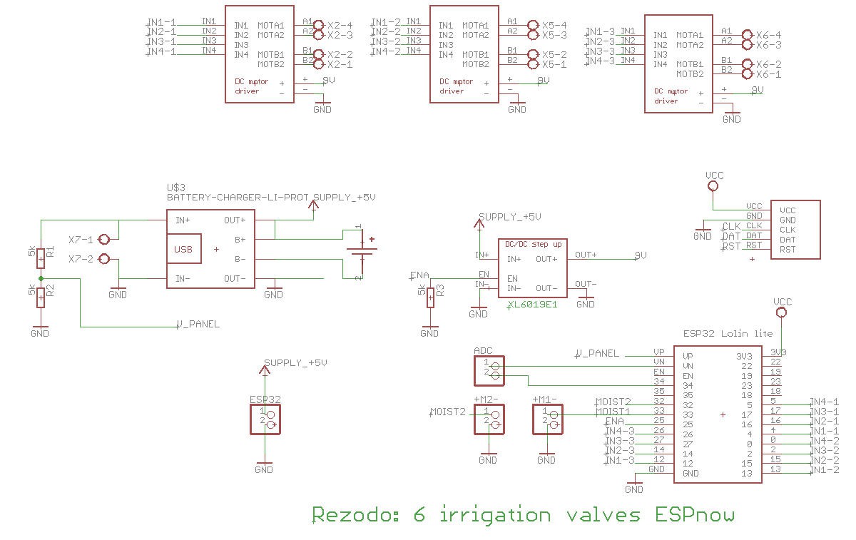
Schematics are pretty much the same as 4 valves board but with one coil driver more and Lora less!
![]()
![]()
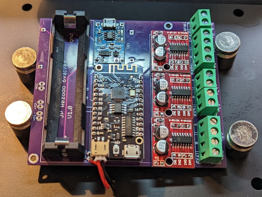
The board is extremely compact, both sides are soldered with DIY modules.
-
Automate your irrigation system with "calendar triggers"
04/20/2023 at 16:41 • 0 commentsWe have a Rezodo Calendar ready to be used.
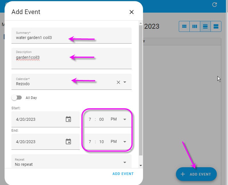
Let's create an event april 20th between 7pm and 7:10pm
Just go into the Rezodo agenda, select the right date and enter a new event
![]()
If you want you can repeat this event. Here I selected "no repeat" option. It will be a single evnt.
The most important field for automation purpose will be the "description". Choose a meaning full short name.
Now we would like that this event triggers some actions...
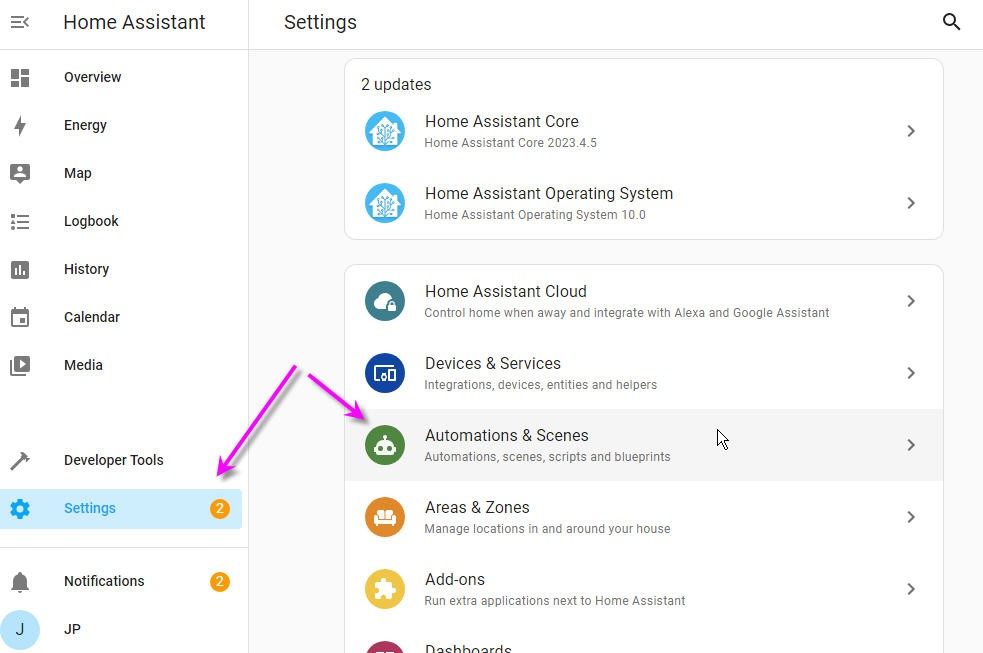
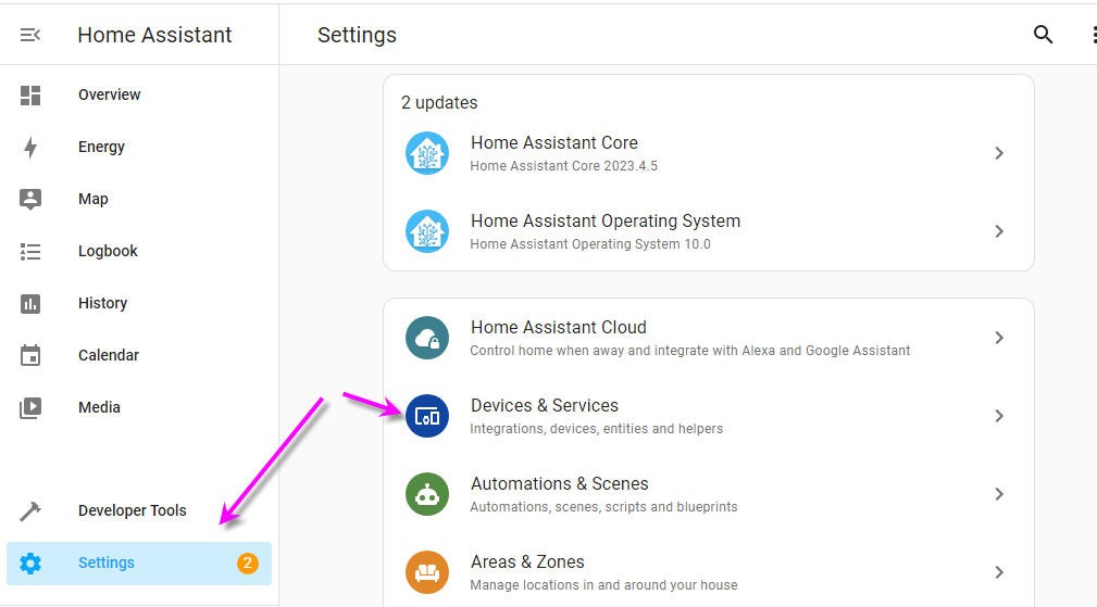
Let's jump to the Settings/automation and scenes menu in HA
![]()
And click on the bottom right button "create automation"
![]()
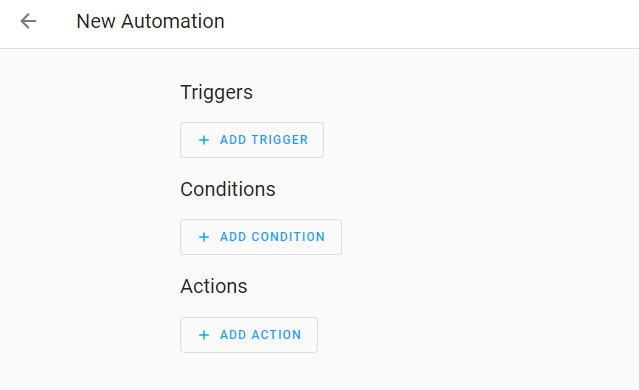
Then select create a new Automation. A screen like this one will open
![]()
So we can add a trigger which under certain conditions will trigger actions... Perfect !
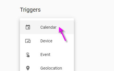
Clcik "Add trigger"
![]()
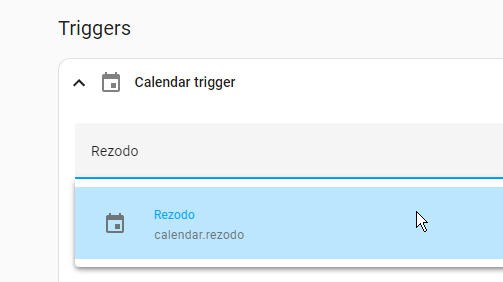
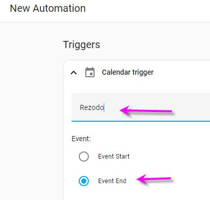
Select "Calendar" and then choose the Rezodo calendar
![]()
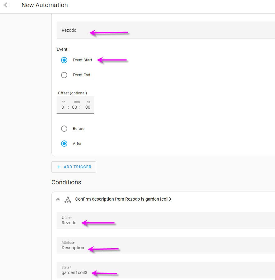
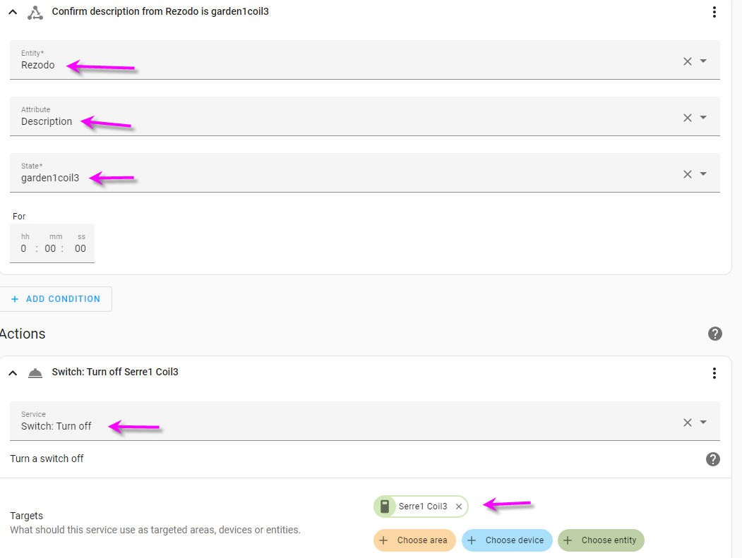
Then we can fill the other fields like this
![]()
- When the event starts into this calendar (at 7:00 Pm remember)
- When the event description is equal to "garden1coil3"
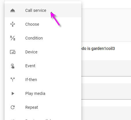
Then we will trigger an action (click on "Add action ")
select tha call service option
![]()
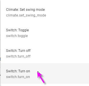
choose Switch turn On into the available services
![]()
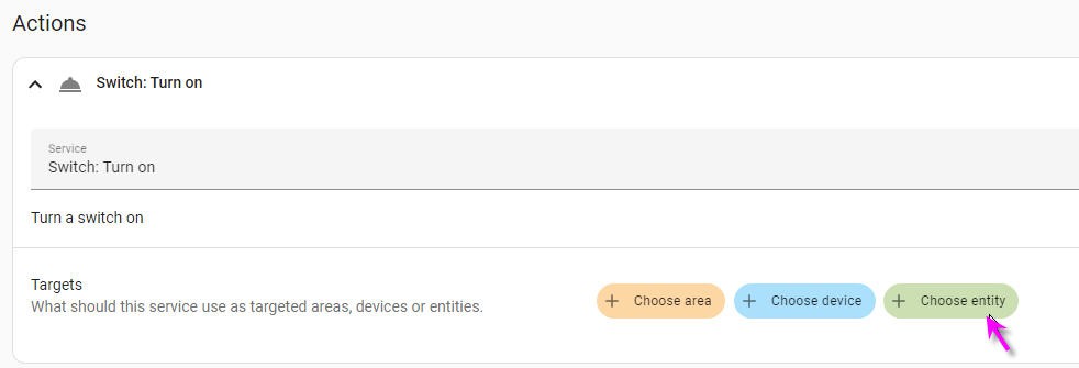
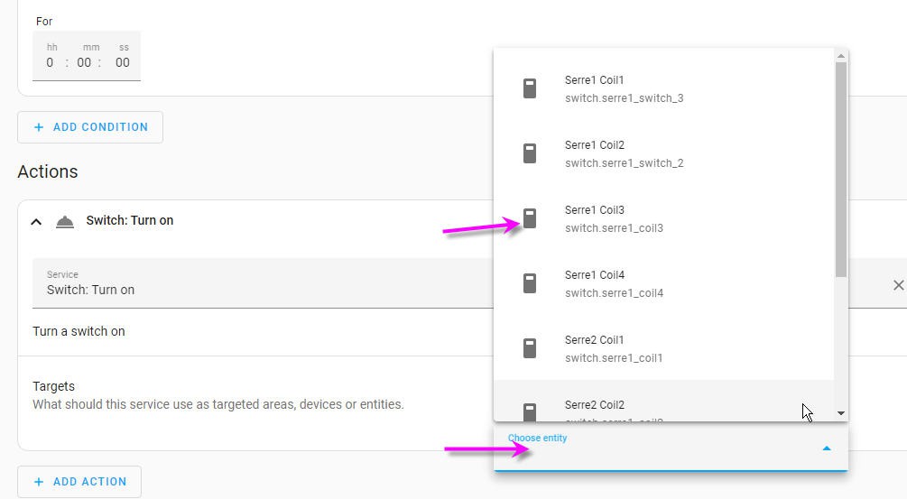
then select the entity to trigger the action
![]()
and of course trigger the right switch to open the right valve in your garden
![]()
here Serre1 coil3 switch defined before.
So to summarize :
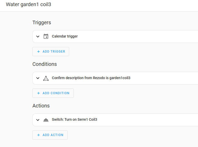
when the event into the calendar will start, it will trigger an automation if the description of this event matches the description we have choosen. And the trigger will turn on the right switch which will in turn send an MQTT message to the Rezodo network.
![]()
Seems complex ? Yes may be a little at first glance. But try it it is finally very logical and sooo powerful !
But now once the valves opens it never switch off....
Well just have to add another event which will be triggered at the end of the calendar slot...
![]()
And follow same process as before but select the switch_Off action!
![]()
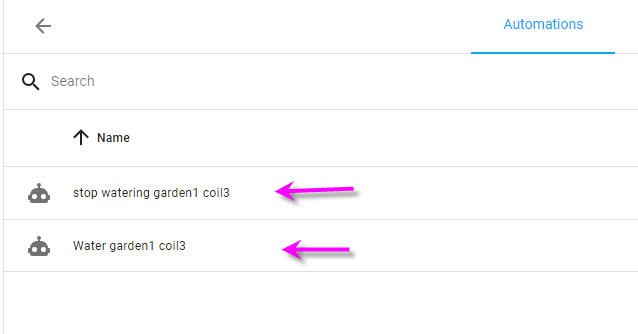
Finally in our Automation tab in Home Assistant we now have two triggers which will be automatically called by teh Rezodo Calendar.
![]()
Of course you can trigger more complex actions (open valve 1, 2 and 3 but not 4... What you want !
-
Adding a calendar to Rezodo
04/19/2023 at 16:23 • 0 commentsOnce again we will use Home assistant integration to add the calendar.
![]()
Click the add an integration
![]()
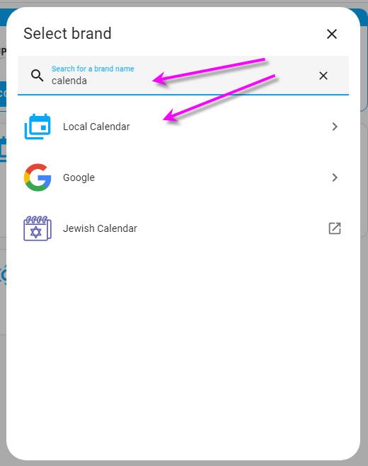
and into the search bar look for "calendar" and you will find the localCalendar add-on.
![]()
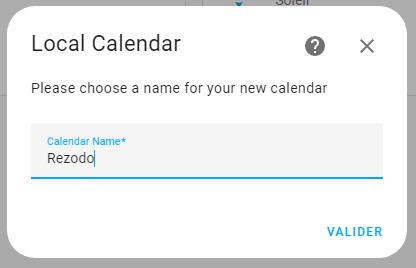
select it and install the calendar with the nice name "Rezodo"!
![]()
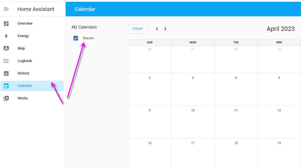
Valid and you get a new integration: the Rezodo calendar
![]()
You now have a calendar tab into the left menu that will open your calendar.
You can have as many calendars you want. For now one is enough: "Rezodo". It's a very clean calendar into which you can add events on specific days/month/year hour minute... with optionnal repetition/exclusion. Well something more or less like the Google Agenda but devoted to home automation.
![]()
-
adding switches to home assistant
04/19/2023 at 12:56 • 0 comments"Once again we will use the power of Home Assistant to add switches to the interface and to allow these switches to publish messages with MQTT.
This is a simple process if you follow these instructions:
add an editor to home assistant
go to the add on store and select "File Editor"
![]()
install it run it
![]()
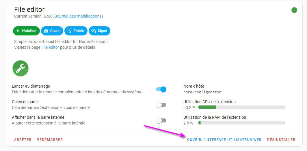
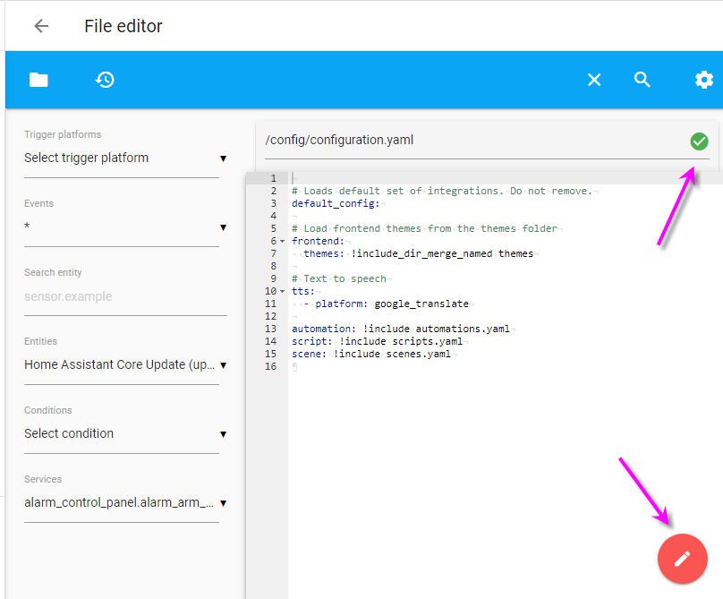
then you can click on "open Web user interface" this will magically open the file editor and the famous "YAML file" of home assistant
![]()
This file handles all teh configuration of your HA. With a new project it is almost empty.
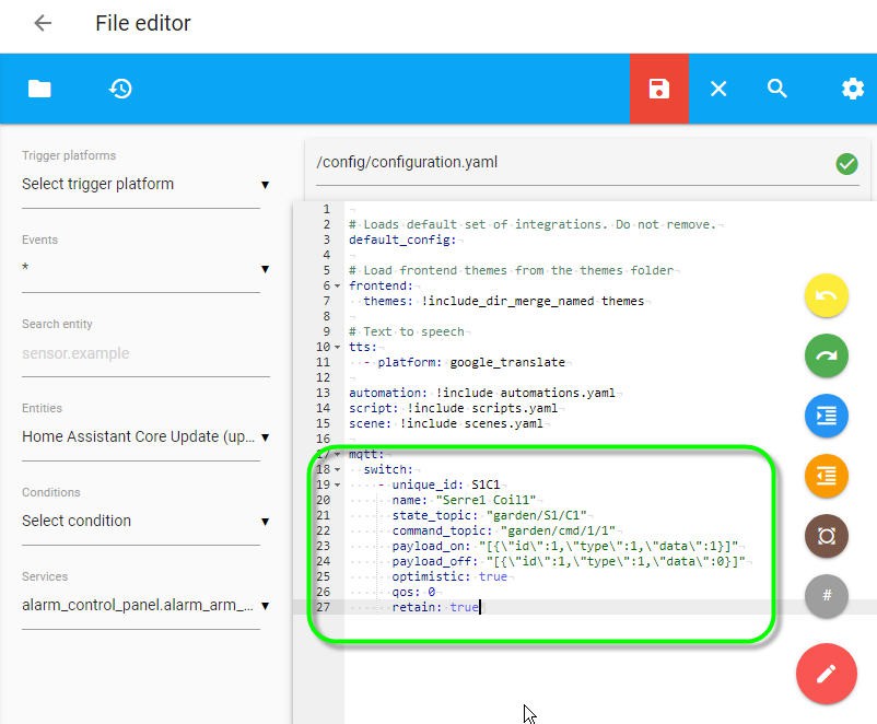
We will add a MQTT switch in this file.
Any time we write something into this file the consistency is cheked and the gren mark on top right corner should remain green. If becoming red it is most likely an error of indentation into your YAML file.... Beware of blank space... they go usually two by two !
To add a switch copy paste these lines:
mqtt:
  switch:
    - unique_id: S1C1
      name: "Serre1 Coil1"
      state_topic: "garden/S1/C1"
      command_topic: "garden/cmd/1/1"
      payload_on: "[{\"id\":1,\"type\":1,\"data\":1}]"
      payload_off: "[{\"id\":1,\"type\":1,\"data\":0}]"
      optimistic: true
      qos: 0
      retain: true
It tells the following:
- we use an MQTT integration
- we add a serie of switches (only one right now)
- this switch has "serre1 Coil1" name (you can change it !)
- more important: this switch will publish an MQTT message to the topic : "garden/cmd/1/1"
- and it will pusblish these JSON messages respectively when On or Off
payload to topic garden/cmd/1/1 à 14:48 : [ { "id": 1, "type": 1, "data": 1 } ]- the switch as an "optimistic" behavior. Even when its state is unknown (first boot) it will be displayed at the off state
- the Quality Of Service (QoS) is set at its lowest level : 0 (see more here) you can change it up to level 2
- Extremely important : this message wil be retained on the broker. This means that any time a client will "subscribe" to this topic, the broker will push the latest received message to the client. So, if the current configuration is kept on the broker side, then any time our Rezodo GTW0 will subscribe to these messages, it will be updated with the latest command sent to the broker : cool !
![]()
Now we can save the YAML file with these lines inserted.
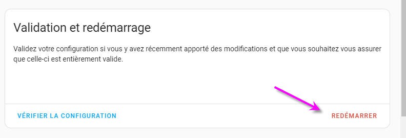
We then need to restart the Home assistant (go to the developer tools, on top of the page)
![]()
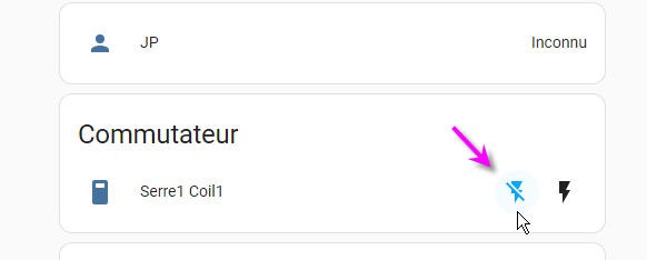
And that's it you have a nice switch on your HA main page
![]()
You can test it using the MQTT add on and see that it works when you change this switch while listening to the " garden/cmd/1:1" topic
As it works for one switch we will now add the 7 missing to configure our Rezodo.
Simply copy paste these lines into the YAML
mqtt:
  switch:
    - unique_id: S1C1
      name: "Serre1 Coil1"
      state_topic: "garden/S1/C1"
      command_topic: "garden/cmd/1/1"
      payload_on: "[{\"id\":1,\"type\":1,\"data\":1}]"
      payload_off: "[{\"id\":1,\"type\":1,\"data\":0}]"
      optimistic: true
      qos: 0
      retain: true

    - unique_id: S1C2
      name: "Serre1 Coil2"
      state_topic: "garden/S1/C2"
      command_topic: "garden/cmd/1/2"
      payload_on: "[{\"id\":1,\"type\":2,\"data\":1}]"
      payload_off: "[{\"id\":1,\"type\":2,\"data\":0}]"
      optimistic: true
      qos: 0
      retain: true

    - unique_id: S1C3
      name: "Serre1 Coil3"
      state_topic: "garden/S1/C3"
      command_topic: "garden/cmd/1/3"
      payload_on: "[{\"id\":1,\"type\":3,\"data\":1}]"
      payload_off: "[{\"id\":1,\"type\":3,\"data\":0}]"
      optimistic: true
      qos: 0
      retain: true

    - unique_id: S1C4
      name: "Serre1 Coil4"
      state_topic: "garden/S1/C4"
      command_topic: "garden/cmd/1/4"
      payload_on: "[{\"id\":1,\"type\":4,\"data\":1}]"
      payload_off: "[{\"id\":1,\"type\":4,\"data\":0}]"
      optimistic: true
      qos: 0
      retain: true

    - unique_id: S2C1
      name: "Serre2 Coil1"
      state_topic: "garden/S2/C1"
      command_topic: "garden/cmd/2/1"
      payload_on: "[{\"id\":2,\"type\":1,\"data\":1}]"
      payload_off: "[{\"id\":2,\"type\":1,\"data\":0}]"
      optimistic: true
      qos: 0
      retain: true

    - unique_id: S2C2
      name: "Serre2 Coil2"
      state_topic: "garden/S2/C2"
      command_topic: "garden/cmd/2/2"
      payload_on: "[{\"id\":2,\"type\":2,\"data\":1}]"
      payload_off: "[{\"id\":2,\"type\":2,\"data\":0}]"
      optimistic: true
      qos: 0
      retain: true

    - unique_id: S2C3
      name: "Serre2 Coil3"
      state_topic: "garden/S2/C3"
      command_topic: "garden/cmd/2/3"
      payload_on: "[{\"id\":2,\"type\":3,\"data\":1}]"
      payload_off: "[{\"id\":2,\"type\":3,\"data\":0}]"
      optimistic: true
      qos: 0
      retain: true

    - unique_id: S2C4
      name: "Serre2 Coil4"
      state_topic: "garden/S2/C4"
      command_topic: "garden/cmd/2/4"
      payload_on: "[{\"id\":2,\"type\":4,\"data\":1}]"
      payload_off: "[{\"id\":2,\"type\":4,\"data\":0}]"
      optimistic: true
      qos: 0
      retain: true
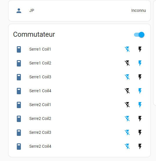
Save it, restart the HA and go to the main page
![]()
Here it is! 8 switches which can command your Rezodo.
Well ... almost... We still need to configure our Arduino code to register to the messages we want.
Open the MQTTsubscription.h file into your FDRS libray folder and add these lines:
client.subscribe("garden/cmd/1/1");
client.subscribe("garden/cmd/1/2");
client.subscribe("garden/cmd/1/3");
client.subscribe("garden/cmd/1/4");
client.subscribe("garden/cmd/2/1");
client.subscribe("garden/cmd/2/2");
client.subscribe("garden/cmd/2/3");
client.subscribe("garden/cmd/2/4");
Save the file and recompile... Now the Rezodo will receive the command messages any time it wakes up.
Cool again !
-
adding MQTT broker to Rezodo
04/19/2023 at 10:06 • 0 commentsHome Assistant as aclear installation procedure for internal MQTT broker. It is an add-on which is well documented.
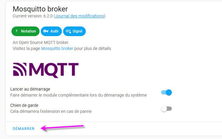
All you have to do is install this add-on clicking on the add integration button
![]()
Then you should look into the Add_on store to find the Mosquitto MQTT
![]()
Finally install and activate it
![]()
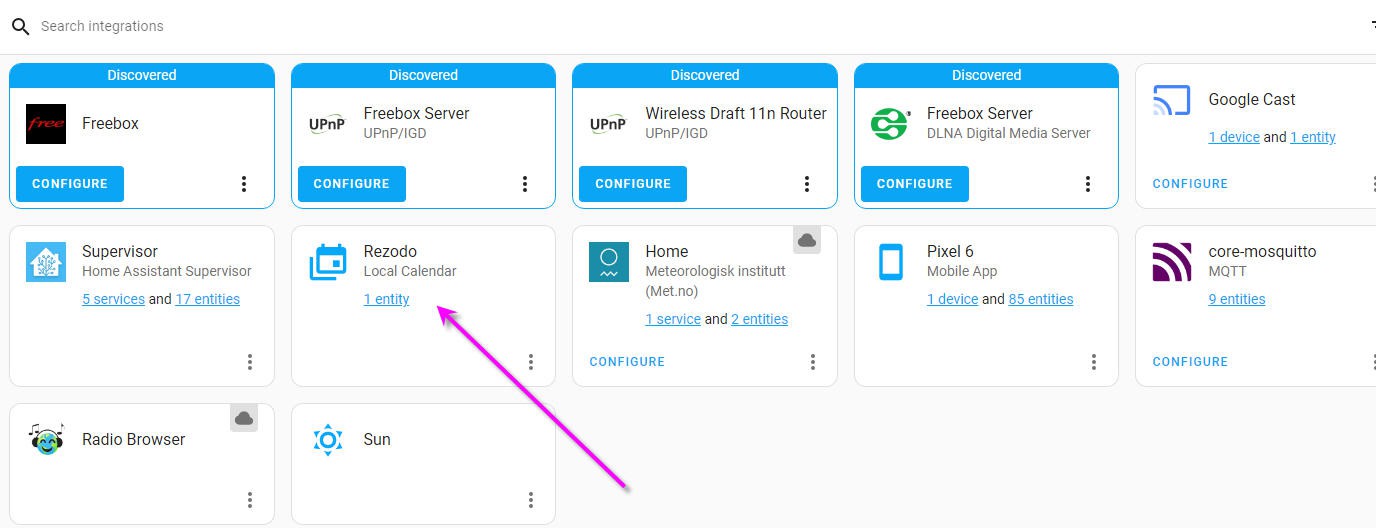
Then you can find it into your integration page
![]()
Simply click to configure the broker and access the default configuration.
Your MQTT broker is ready to receive and lsiten to messages.
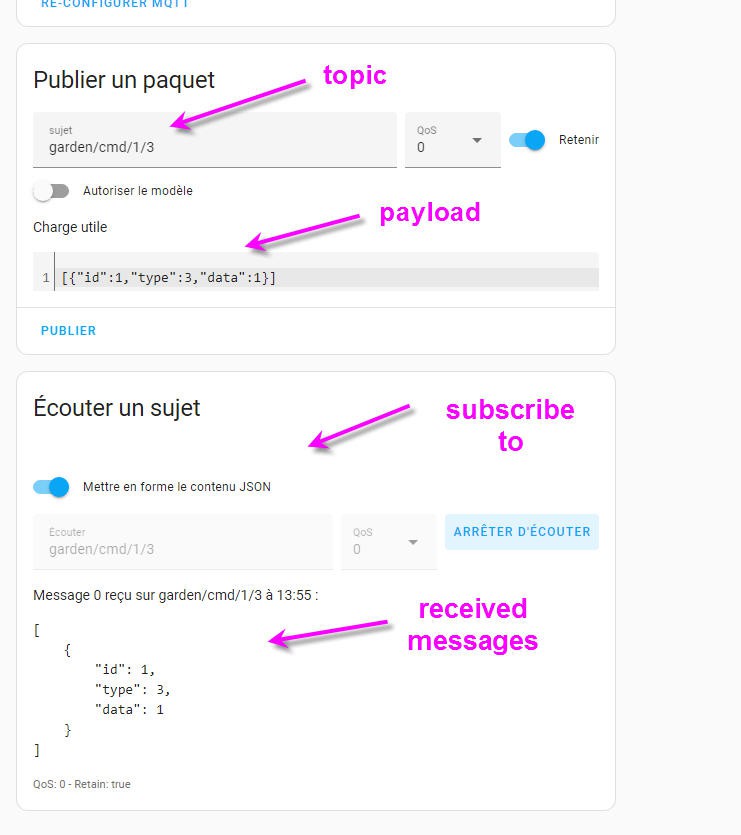
If you click again on teh configuration button then you even get a test page to send and listen to packets.
![]()
In this simple example I have tested the broker while manually sending a command message to my Rezodo GTW1 coil3 (topic field)
And with a JSON payload compliant with FDRS API
Then I can subscribre to this message and start listening the broker.
As soon as I click the publish button, the message is send and displayed in the received messge part of the screen.
Easy no ?
That's it your MQTT broker is installed and configured. But now we can do more!
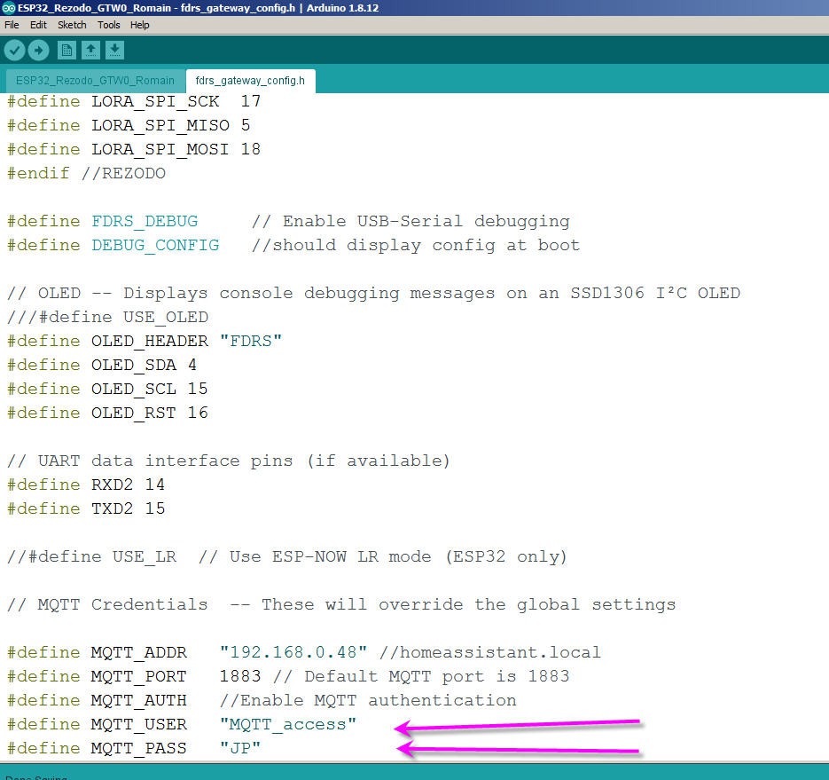
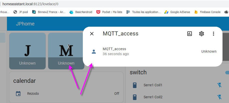
You will need to create an account in Home Assistant for the GTW0 to be allowed to access this MQTT broker.
![]()
The credentials you choose must be entered into the fdrs_gateway_config.h as shown above.
This HASS account is a regular one which is preferably different from your personnal account.
![]()
-
Installation of Home Assistant
04/19/2023 at 08:41 • 0 commentsInstallation of Home Asssistant will require a Linux operating system.
If you are on a windows PC then you will need to install virtualisation into this system.
This may seem to be complex, but frankly speaking it is not !
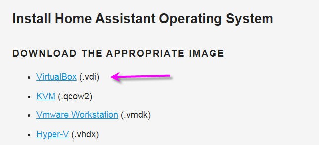
You even have several options. I did choose the first one: installing VirtualBox to run a VDI image of home assistant
![]()
I will go through this installation process, but if you want you can choose any other solution!
- click on the virtualBox.vdi link above and download the home Assistant virtual machine image
- go to VirtualBox site and search for the version suitable for your operating system
![]()
For my very old PC (more than 12 years old) I had to go to the "Old_builds" section and select the latest release working for 32 bits OS... It was the 5.2 versions and more specifically the 5.2.44
I must admit that I was a little afraid to install such an old "unsupported version" on my PC but it worked without any issue.
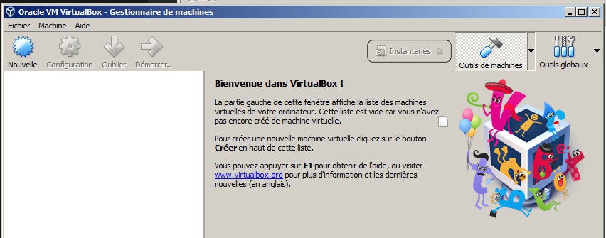
Install it and run it.
You should see a windows like this one
![]()
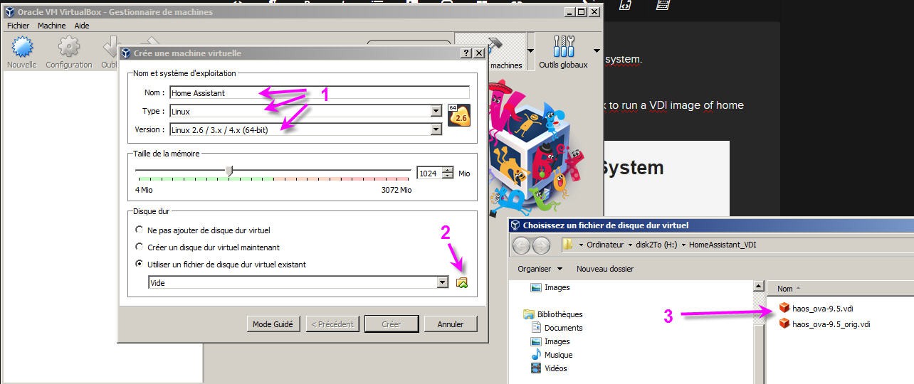
Click on the top left button to create a new virtual machine
![]()
then:
- name your machine as you want, select Linux OS and latest 4.X (64bits) version
- then choose your home assistant virtual machine image
- open it
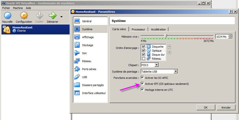
When done click on the configuration button.
you have to go to the "system" tab and activate the EFI option into your virtual mother board
![]()
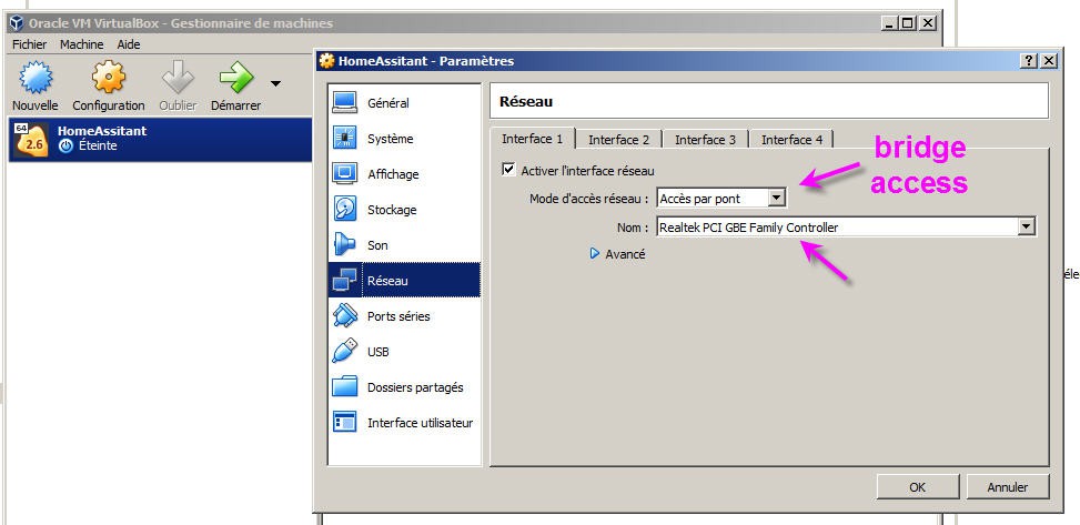
Then go to the "network" menu and select the "bridge" option. You will need to connect your PC to your network (wifi is not supported)
![]()
And that's it.
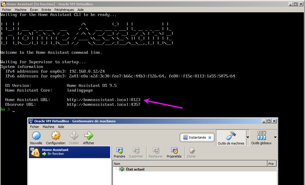
You can now start your Virtual machine with the big green arrow. After a while Home Assistant will be launched into VirtualBox. Your home assistant server is running.
![]()
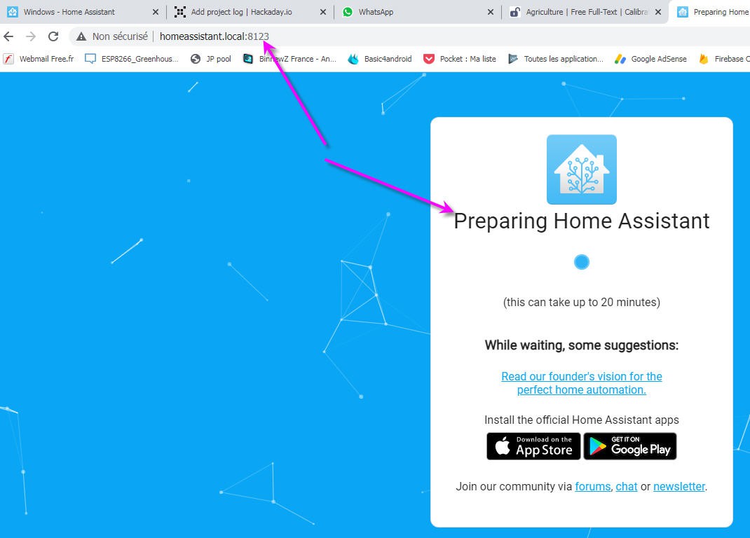
Now launch its web interface using your browser and typing the given URL http://homeassistant.local:8123
Your home assistant is indeed accessible on your local network. This is a safe way for the moment. But iti is of course possible to expose HA on internet. This will be explained later.
![]()
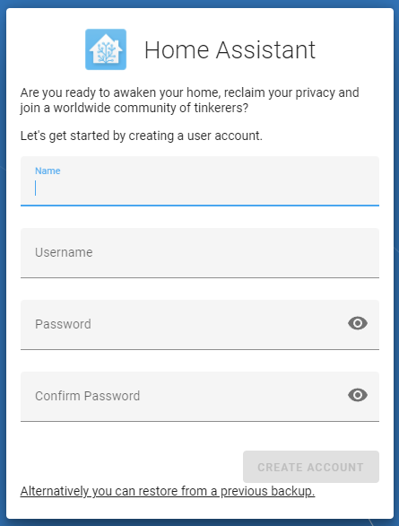
after a few minutes, you can now "onboard" home assistant
![]()
select any name and credentials you want!
and a new "home" is on your screen
![]()
Well it's an "empy" home into which we will now add a Rezodo system !
-
interface with ThingSpeak platform
04/18/2023 at 15:50 • 0 commentsInterfacing Rezodo with ThingSpeak is very simple. You can even look at tutorial devoted to smart agriculture applications
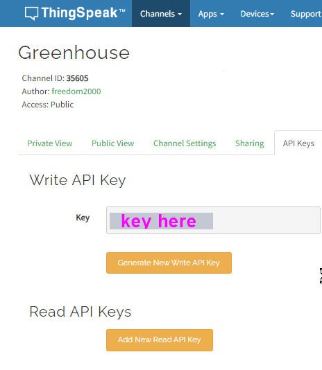
In a few words, you need first to create an account then a channel and get an API key.
![]()
Once you have your key, simply enter it into the arduino code. Only two lines!
// ThingSpeak settings
char thingserver[] = "api.thingspeak.com";
String writeAPIKey = "CNP89KTF45WWS4YF";
Then this procedure will upload two fields to your channel:
void ThingSpeakPost(void)
{
  WiFiClient client;
  if (!client.connect(thingserver, 80))
  {
    Serial.println("Connection failed");
    client.stop();
    return;
  }
  else
  {
    // Create data string to send to ThingSpeak.
    String data =  "field1=" + String(sensorValues[1][0][0]) + "&field2=" + String(sensorValues[2][0][0])  ; //shows how to include additional field data in http post
#ifdef W_DEBUG
    // Just for testing, print out the message on serial port
    Serial.println("==> ThingSpeak POST message ");
    Serial.println(data);
#endif
    // POST data to ThingSpeak.
    if (client.connect(thingserver, 80)) {
      client.println("POST /update HTTP/1.1");
      client.println("Host: api.thingspeak.com");
      client.println("Connection: close");
      client.println("User-Agent: ESP32WiFi/1.1");
      client.println("X-THINGSPEAKAPIKEY: " + writeAPIKey);
      client.println("Content-Type: application/x-www-form-urlencoded");
      client.print("Content-Length: ");
      client.print(data.length());
      client.print("\n\n");
      client.print(data);
      delay(300);
    }
#ifdef DEBUG_THINGSPEAK
    // Just for testing, print out the message on serial port
    Serial.println("==> ThingSpeak POST message ");
    Serial.println(data);
#endif
    client.stop();
  }
}
As you can see values are passed as strings and uploaded inside a html POST. Nothing complex!
This being done you have access to the full power of this platform.
Channels can even be public or private. Have a look to the sensor values here (only one moisture probe "field2" is connected while dummy values are sent to field1 !)
-
soil moisture probe
04/18/2023 at 09:51 • 0 commentsSoil moistures probes are based on 3 classical technologies:
- resistive probes
- capacitive probes
- tensiometer probes
Each technologiy has advantages and drawbacks.
- resistive probes wear down when using as their electrodes will destroy with electrolysis when current is passing through them
- tensiometer probes are probably more precise but more expensive. They also need more maintenance
- finally capacitive probes are the most commun as they are cheap, quite precise and do not destroy during time
Have a look at this page for more informations.
I decided to build a capacitive probe which will use the embeded "touch pad" sensors of ESP32 MCU.
Indeed a capacitive soilmoisture sensor is no more than a capacitor composed of a positive plate, a negative plate and the gap between the plates known as di-electric.
![]()
A capacitive moisture sensor works by measuring capacitance changes caused by the changes in the dielectric. It does not measure soil moisture directly (as pure water does not conduct electricity well), instead it measures the ions that are dissolved in the moisture. Capacitive measuring basically measures the dielectric that is formed by the soil and the water is the most important factor that affects the dielectric.
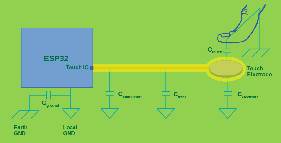
And the ESP32 touchpad does exactly the same with your finger on the sensing plate !
Here is what Expressif is writing on his "touchpad" sensor :
"A touch sensor system is built on a substrate which carries electrodes and relevant connections under a protective flat surface. When a user touches the surface, the capacitance variation is used to evaluate if the touch was valid".
![]()
If we replace the finger by soil it should work !
Expressif API provides a way to measure the number of times the capacitance will charge/discharge when connected to a square wave signal. As the capacitance changes mainly with the soil humidity, this number of charges will also change.
To get better values you should use the "raw measurement" mode of the touchpad sensor.
As said, the touch sensor will count the number of charge/discharge cycles over a fixed period of time (specified by
<span class="pre">touch_pad_set_measurement_clock_cycles()</span>). The count result is the raw data that read from<span class="pre">touch_pad_read_raw_data()</span>. After finishing one measurement, the touch sensor will sleep until the next measurement start, this interval between two measurements can be set by<span class="pre">touch_pad_set_measurement_interval()</span>.And here is the intialization of this API under Arduino IDE:
 //soil moisture probes initialization
  Serial.println("measuring moisture");
  touch_pad_init();
  touch_pad_set_voltage(TOUCH_HVOLT_2V7, TOUCH_LVOLT_0V5, TOUCH_HVOLT_ATTEN_1V);
  touch_pad_config(TOUCH_PAD_NUM8, 0); //T8
  // touch_pad_config(TOUCH_PAD_NUM0, 0); //T0 does not work if coil driver is soldered(will work if not soldered)
  // touch_pad_config(TOUCH_PAD_NUM2, 0); //T2 does not work if coil driver is soldered(will work if not soldered)
  // touch_pad_config(TOUCH_PAD_NUM3, 0); //T3 does not work if coil driver is soldered(will work if not soldered)
My board exposes 4 touch pads pins but 3 of them are also connected to the motors drivers pins.
So if you solder the two drivers only soilMoisture M1 will work which is T8 on the ESP32.
To read the raw value, it's very simple :
 //humidity sensors: read touch output
  uint16_t output;
  touch_pad_read(TOUCH_PAD_NUM8, &output);  //T8 or M1
  M1 = float(output);
But does it work ?
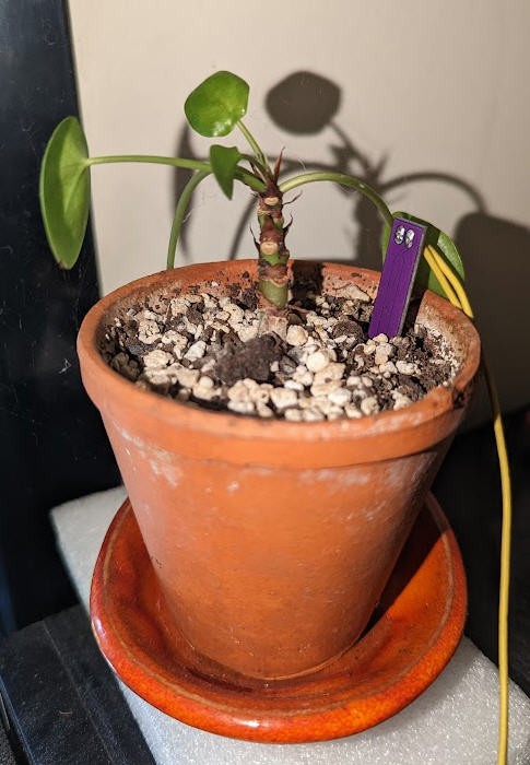
For testing purposes I have put the sensor into a small potted plant.
![]()
And I have watered it on an almost regular basis.
Results on next log !
-
Configuring the FDRS network
04/16/2023 at 16:02 • 0 commentsConfiguring the FDRS network is a fairly easy operation. We have just to tell the library how the routing of messages should be done.
To do so we just have to open the fdrs_gateway_config.h file for each GTW and modify the predefined values in accordance with the choosen topology of the network.
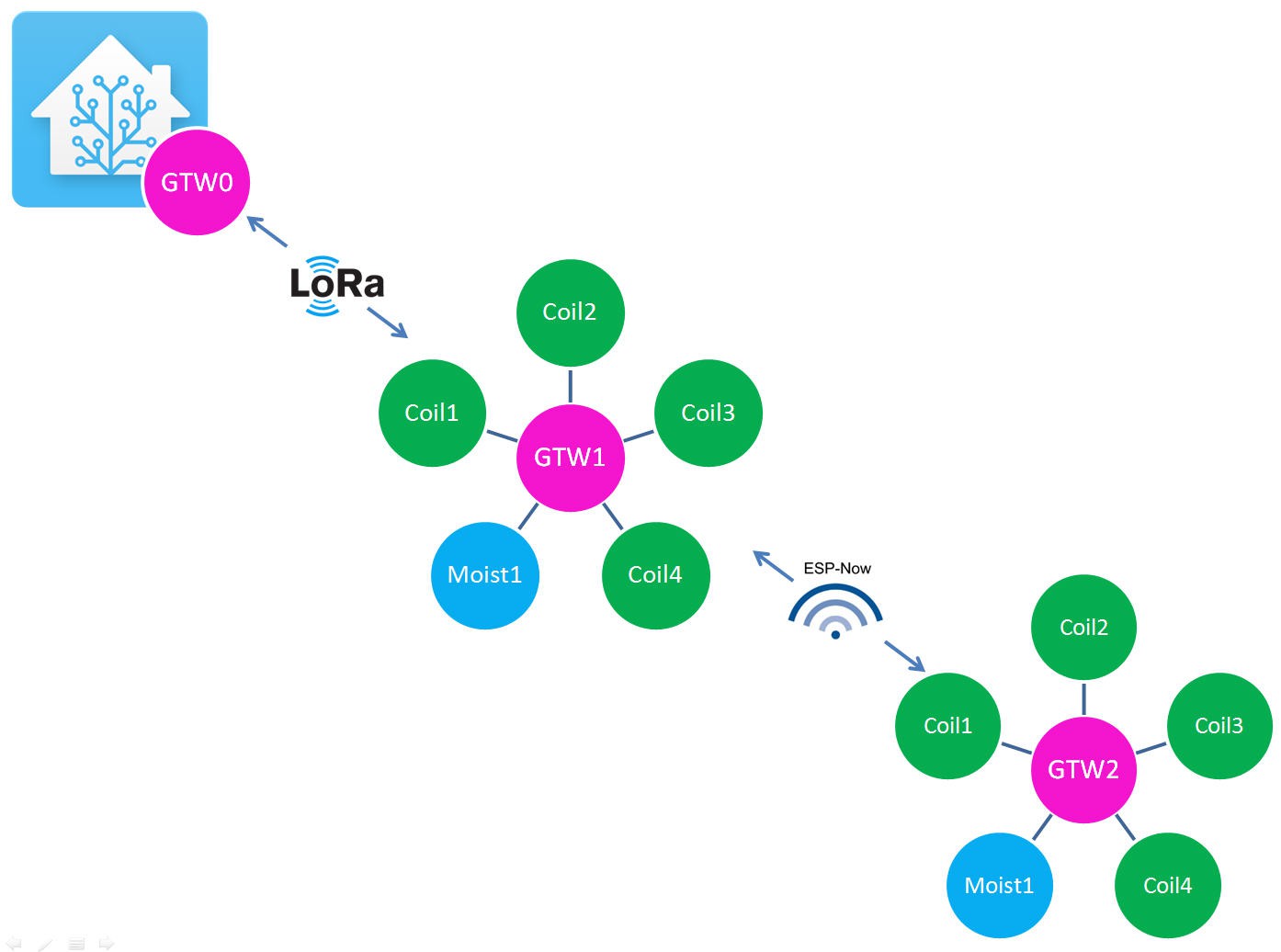
In our case we have 3 gateways to configure.
![]()
GTW2 configuration
We will start by the easiest one GTW2. It is only linked to one neighbor GTW1 via ESPnow protocol.
We can write the following configuration into the .h file
//Addresses
#define UNIT_MAC           0x02  // The address of this gateway

#define ESPNOW_NEIGHBOR_1  0x01  // Address of ESP-NOW neighbor #1
#define ESPNOW_NEIGHBOR_2  0x99  // Address of ESP-NOW neighbor #2
//#define LORA_NEIGHBOR_1  0x99  // Address of LoRa neighbor #1
//#define LORA_NEIGHBOR_2  0x99  // Address of LoRa neighbor #2

// Interfaces
#define USE_ESPNOW
#define USE_LR      // Use ESP-NOW LR mode (ESP32 only)
//#define USE_LORA
Doing this we tell the library that
- our GTW has the MAC address 2. It is indeed GTW2
- its first neighbor is ESPNOW_NEIGHBOR_1 with the MAC Address 1 --> GTW1
- its second neighbor via ESPnow does not really exist, it has a dummy MAC address of 99
- it does not have Lora neighbors (commented two lines)
Then we tell that this GTW only uses ESPNow protocol and must be configured with the Long Range option
And that's all for the network configuration.
Now we must choose the routing actions to be performed by FDRS. It's also a matter of configuration.
// Routing
// Options: sendESPNowNbr(1 or 2); sendESPNowPeers(); sendLoRaNbr(1 or 2); broadcastLoRa(); sendSerial(); sendMQTT();
//for sendSerial();  you should type values in JSON format:  [{ id: 1, type: 6, data: 384 }] or array [{ id: 1, type: 6, data: 384 },{ id: 2, type: 6, data: 385 }]and ckick send in serial monitor
//#define ESPNOWG_ACT
//#define LORAG_ACT
//#define SERIAL_ACT
//#define MQTT_ACT
#define INTERNAL_ACT   sendESPNowNbr(1);
//#define ESPNOW1_ACT    sendSerial();
//#define ESPNOW2_ACT
//#define LORA1_ACT
//#define LORA2_ACT
Among the long list of options available (have a look at the FDRS documentation ) I simply selected that I want to route the messages internally posted by the gateway via ESPNow protocol and to send the message to the first neighbor (which is GTW1).
Remember that an INTERNAL_ACT is triggered when using LoadFDRS() and SendFDRS() functions into the code.
loadFDRS(M1, SOIL_T, id); //will send back these data readings using INTERNAL_ACT event. Id 0x200 = GTW2 sensor0
sendFDRS();
We have finished with GTW2. Let's do the same with GTW1
GTW1 configuration
GTW1 is a little more complex to configur than GTW2 as it is linked to GTW0 and GTW2 respectively via Lora and ESPNow.
However the same logic apply. You only have to change a few prameters into the fdrs_gateway_config.h file
//  GATEWAY CONFIGURATION

//Addresses
#define UNIT_MAC           0x01  // The address of this gateway

#define ESPNOW_NEIGHBOR_1  0x02  // Address of ESP-NOW neighbor #1
#define ESPNOW_NEIGHBOR_2  0x99  // Address of ESP-NOW neighbor #2
#define LORA_NEIGHBOR_1    0x00  // Address of LoRa neighbor #1
#define LORA_NEIGHBOR_2    0x99  // Address of LoRa neighbor #2
Doing this we tell the library that
- our GTW has the MAC address 1. It is indeed GTW1
- its first neighbor is ESPNOW_NEIGHBOR_1 with the MAC Address 2--> GTW2
- its second neighbor via ESPnow does not really exist, it has a dummy MAC address of 99
- its first Lora neighbor is LORA_NEIGHBOR_1 with the MAC Address 0--> GTW0
- its second Lora neighbor does not exist, it has a dummy MAC address of 99
Now we will describe its interfaces and routing options
// Interfaces #define USE_ESPNOW #define USE_LORA // Routing // Options: sendESPNowNbr(1 or 2); sendESPNow(0xNN); sendESPNowPeers(); sendLoRaNbr(1 or 2); broadcastLoRa(); sendSerial(); sendMQTT(); //sendSerial() example type: [{ id: 1, type: 6, data: 384 }] or array [{ id: 1, type: 6, data: 384 },{ id: 2, type: 6, data: 385 }]and ckick send in serial monitor #define ESPNOWG_ACT #define LORAG_ACT #define SERIAL_ACT #define MQTT_ACT #define INTERNAL_ACT sendLoRaNbr(1); //when packet is entered internally (loadFDSR(), sendFDRS()) #define ESPNOW1_ACT sendLoRaNbr(1); //when packet comes from ESPnow1 Neighbor #define ESPNOW2_ACT #define LORA1_ACT sendESPNowNbr(1); //when packet comes from Lora1 Neighbor #define LORA2_ACT- So GTW1 is using both Lora and ESPNow interfaces
- when entering values from our arduino sketch we trigger INTERNAL_ACT action which will send the message to Lora neighbor1 that is GTW0. The message is thus going "upstream".
- when a message is arriving from Lora neighbor 1 (GTW0) it triggers the LORA1_ACT action which will route the message to ESPNowNeighbor1 (GTW2)? The message is going "downstream".
- When a message is arriving from ESPnow neighbor1 (GTW2) it is routed to Lora Neighbor1 (GTW0). This message will also go upstream.
And that's it !
Of course, as you are using a lora module you must describe its pins in the ESP32 board. Here it is for our Rezodo board.
// LoRa Configuration
// LoRa Configuration for REZODO purple board
#define RADIOLIB_MODULE RFM95
#define LORA_SS 27
#define LORA_RST 14
#define LORA_DIO 12
#define LORA_BUSY -1
//#define USE_SX126X


#define CUSTOM_SPI
#define LORA_SPI_SCK 26
#define LORA_SPI_MISO 35
#define LORA_SPI_MOSI 25
We have finished with GTW1. Let's do the same with GTW0
GTW0 configuration
And finally we must configure our master gateway GTW0.
This one is linked only to GTW1 on downstream side and will be connected to internet via MQTT protocoll.
Thus its configuration becomes
//Addresses #define UNIT_MAC 0x00 // The address of this gateway //#define ESPNOW_NEIGHBOR_1 0x99 // Address of ESP-NOW neighbor #1 //#define ESPNOW_NEIGHBOR_2 0x99 // Address of ESP-NOW neighbor #2 #define LORA_NEIGHBOR_1 0x01 // Address of LoRa neighbor #1 #define LORA_NEIGHBOR_2 0x99 // Address of LoRa neighbor #2- our GTW has the MAC address 0. It is indeed GTW0
- ESPnow negihbors are not used, they havz a dummy MAC address of 99
- its first Lora neighbor is LORA_NEIGHBOR_1 with the MAC Address 1--> GTW1
- its second Lora neighbor does not exist, it has a dummy MAC address of 99
Now we will describe its interfaces and routing options
// Interfaces
//#define USE_ESPNOW
#define USE_LORA
#define USE_MQTT


// Routing
// Options: sendESPNowNbr(1 or 2); sendESPNow(0xNN); sendESPNowPeers(); sendLoRaNbr(1 or 2); broadcastLoRa(); sendSerial(); sendMQTT();
#define ESPNOWG_ACT
#define LORAG_ACT
#define SERIAL_ACT
#define MQTT_ACT        sendLoRaNbr(1);
#define INTERNAL_ACT    sendLoRaNbr(1);
#define ESPNOW1_ACT
#define ESPNOW2_ACT
#define LORA1_ACT
#define LORA2_ACT
Quite simple as only MQTT_ACT will route the message to GTW1 and same thing for messages entered internally with INTERNAL_ACT.
Finally we must configure Lora pins as for GTW1.
And we must also setup our MQTT configuration
// MQTT Credentials  -- These will override the global settings

#define MQTT_ADDR   "192.168.0.48" //homeassistant.local
#define MQTT_PORT   1883 // Default MQTT port is 1883
#define MQTT_AUTH   //Enable MQTT authentication
#define MQTT_USER   "MQTT_access"
#define MQTT_PASS   "JP"
But this will be explained later!
This was a "complex" post but needed to understand the easy logics of FDRS library.
Our Rezodo network is ready now to be tested... but we need still to install our home automation platform!
Rezodo: Long Range irrigation and weather station
Rezodo aims at building a distributed irrigation system and a weather station with farmers. It's also a fully open platform for IoT learning
 JP Gleyzes