 Yann Guidon / YGDES
Spinoff from #Not an Ethernet Transceiver
I need to split the serdes/coder/AFE part from the scrambler/parity/buffer/FSM part to keep them manageable, there are so many aspects to handle at once... See earlier discussions at:
- 42. The "same" symbol
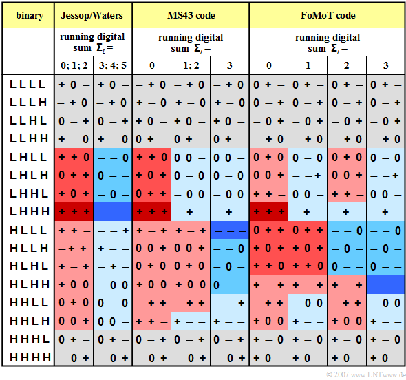
- 43. PAM3 and the bi-Trits
- 45. Constellation 2
- 59. MAC & PHYs
- 62. Sub-protocol: QSDE
- 63. miniPHY
and much more...
-o-O-0-O-o-
Logs:
1. Rotating constellations
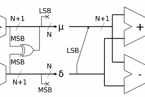
2. The "Same" circuit
3. Drift/Bias evaluation
4. Reverse antibias
5. 4B4T: An extended ternary Manchester code and its implications
6. 4B3T
7. Gearbox
8. Ternary Viterbi
9. Decoder architecture
10.
11.
12.
13.
14.
15.
16.
.
.


 Jac Goudsmit
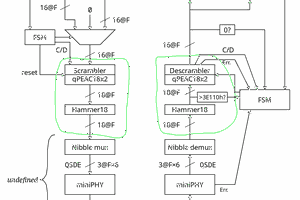
The encoder could generate about any signal but it's only hypothetical if I can't decode it.
So the focus is on the decoder.