 jeremy.geppert
Why is it called SAOfinity?
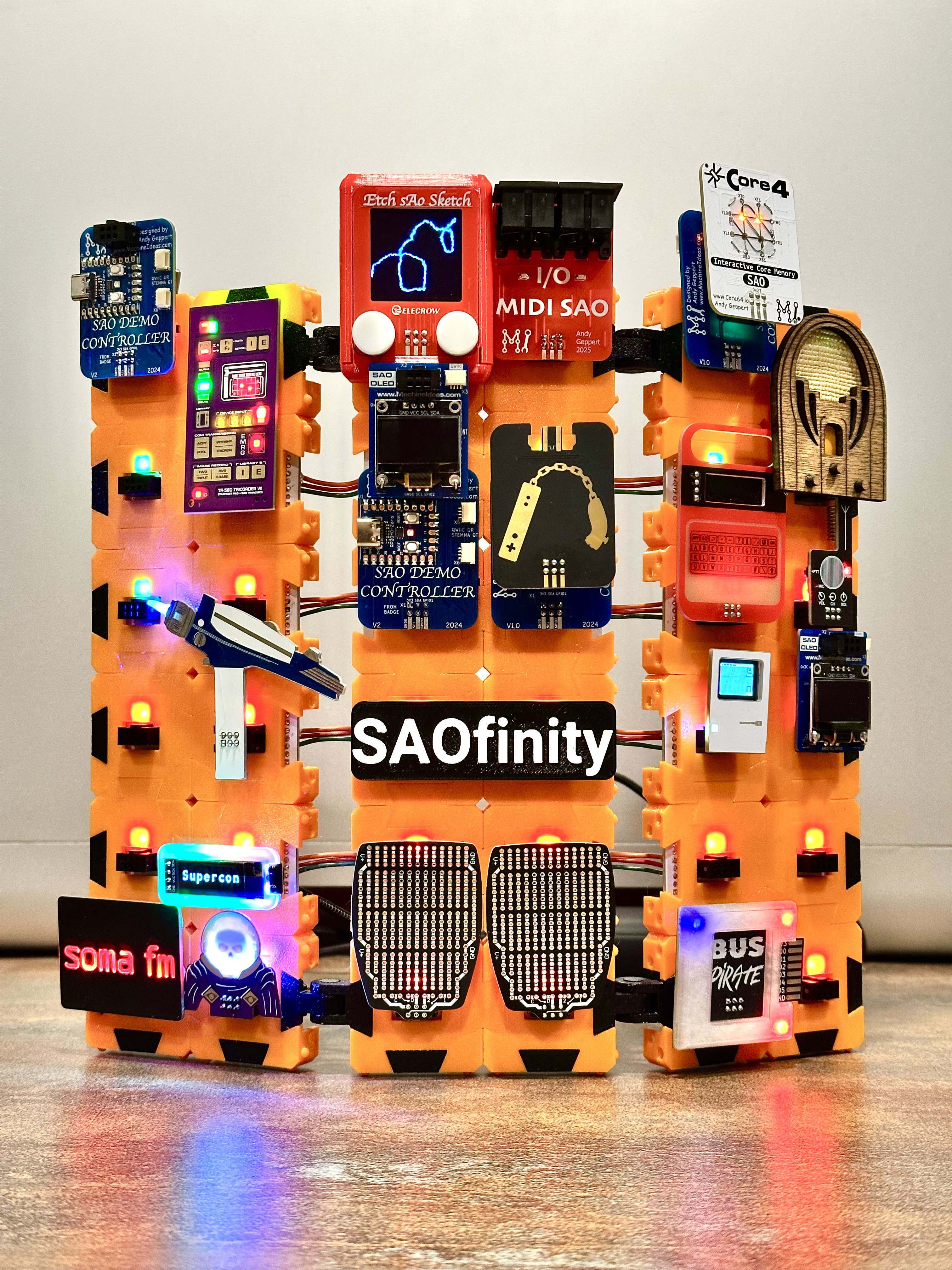
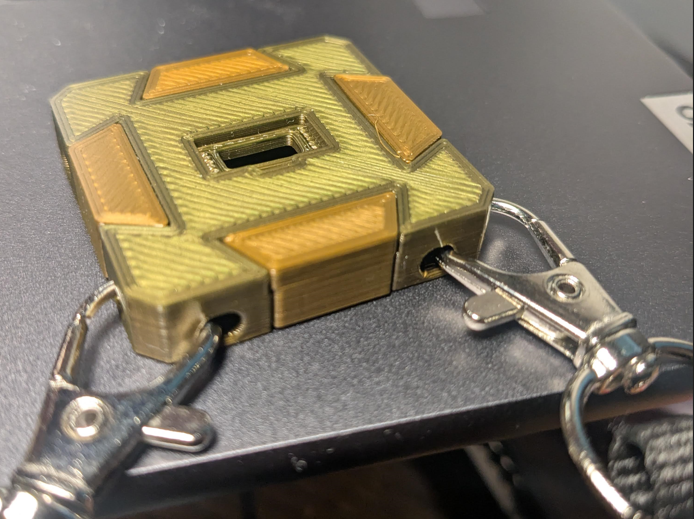
The first prototype was 1.5" x 1.5" and I didn't know what to call it. [@Andy Geppert] pointed out that it was very close (3.9mm) to the Gridfinity organization system size of 42x42mm. I had no good reason not to bump it up to that size and call it SAOfinity. It basically named itself.
Guiding Principles: Inexpensive. Low barrier: Anyone can make them. No custom board necessary. Modular. Expandable.
Getting Started:
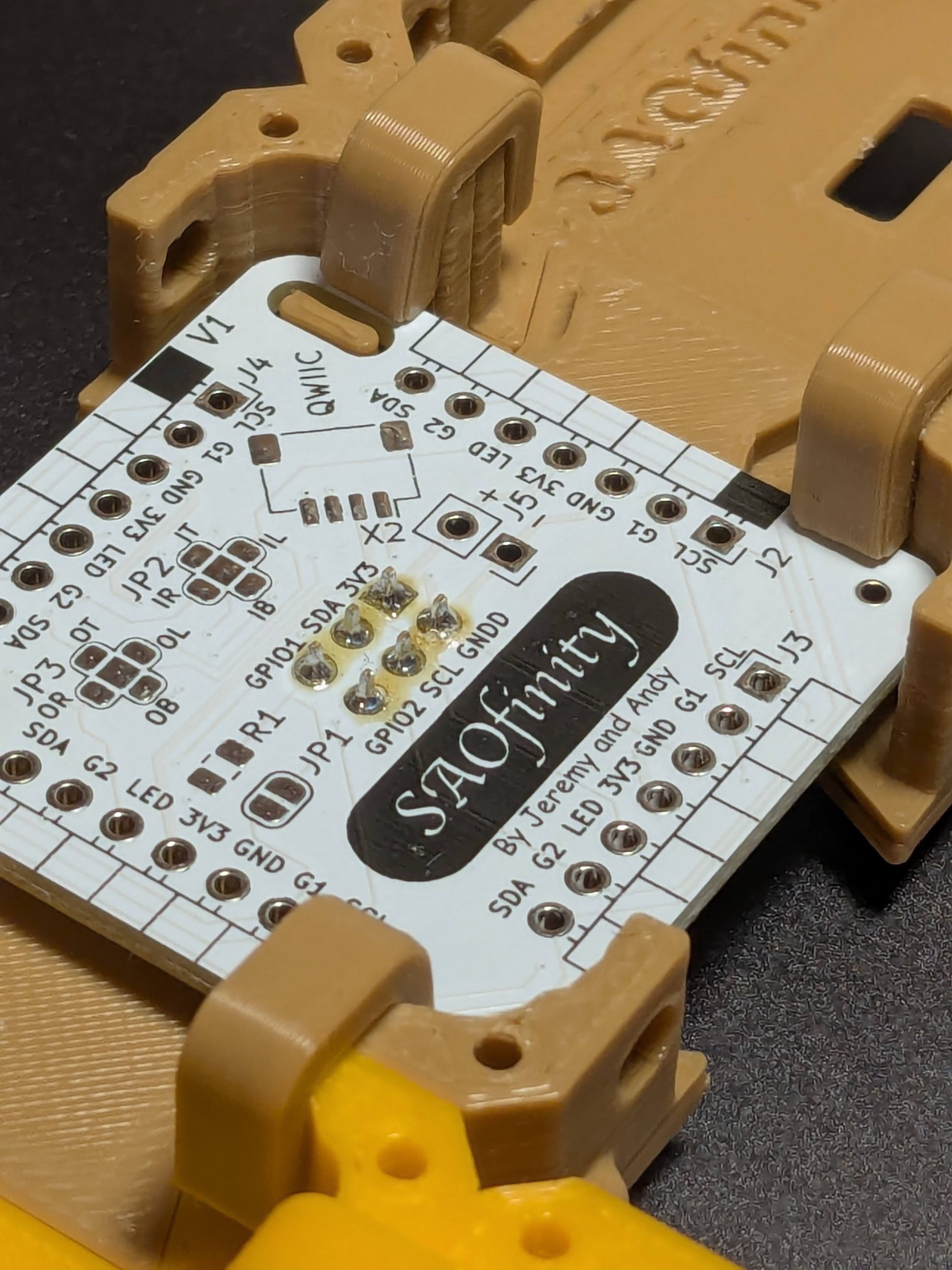
At it's most basic form you can make this system with only a 3D Printer, Glue and the female 6 pin SAO connector. However, you can also add a chunk of protoboard to make connecting wires easier and better secure the connector.
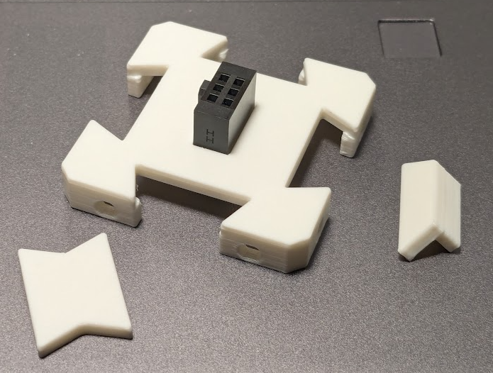
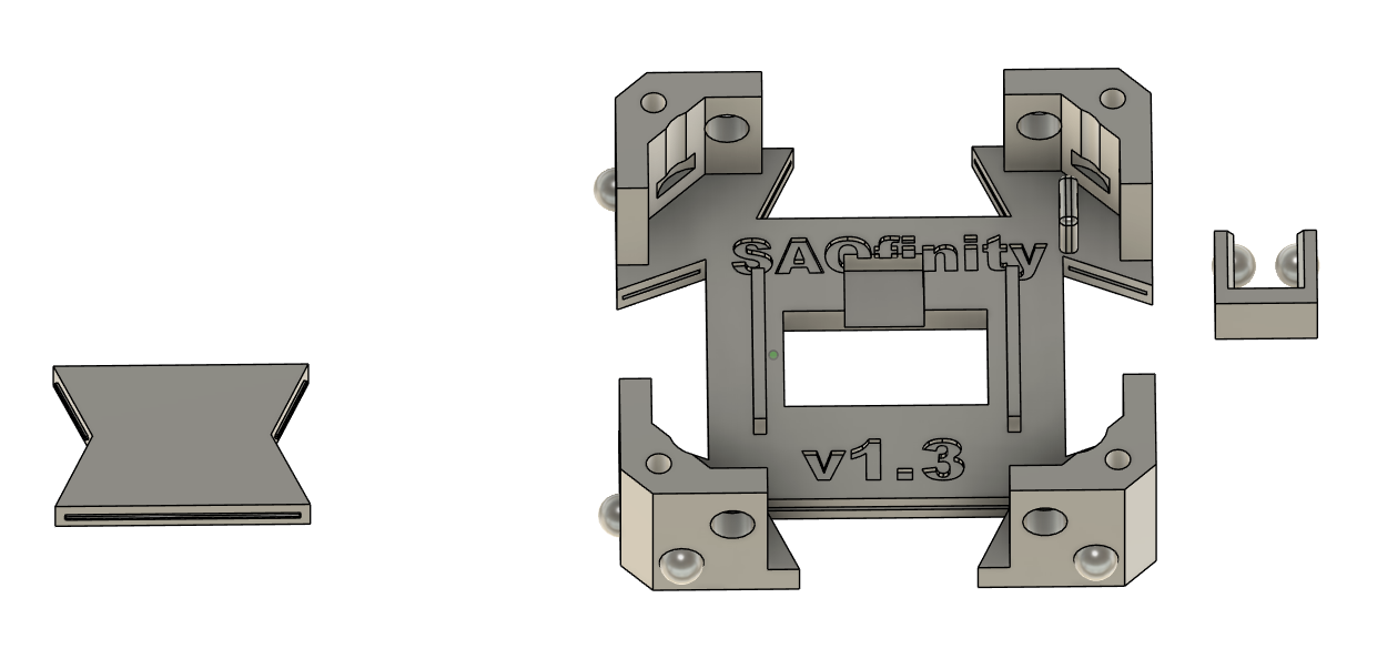
There are 3 primary parts:
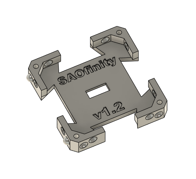
1, The basic "grid". (with SAO female connector)
2. The "bow tie" for connecting grids.
3. The "edge plug" for terminating the edges of whatever shape
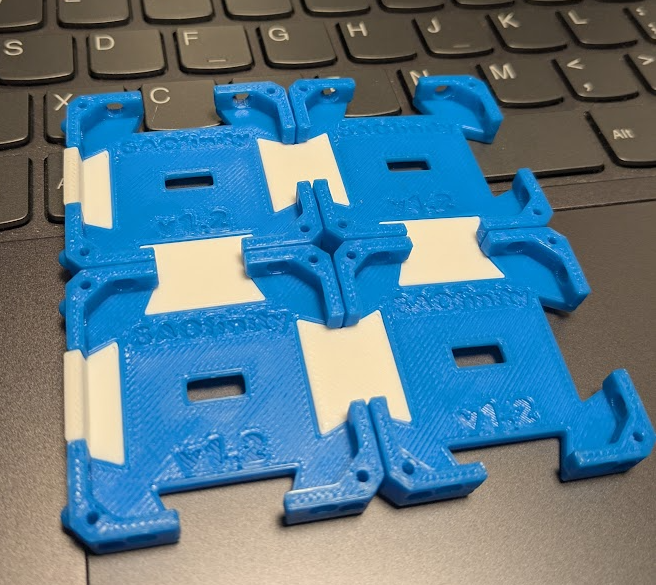
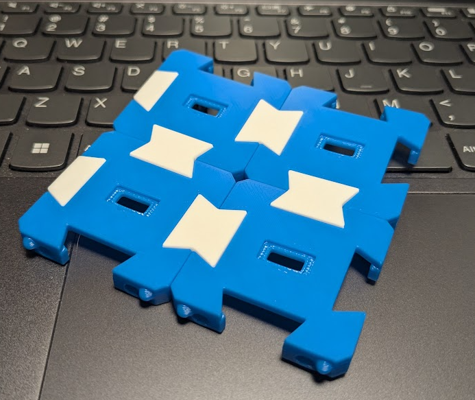
Assembly:
1. Print the number of grids, bow ties and edge plugs you need and snap them together. There are "stops" to prevent over inserting the bow ties and edge plugs. You could add glue to the joints to make it more permanent and rugged.
2, If you don't plan to use protoboard on the back, use CA glue to secure the connector into the recess.
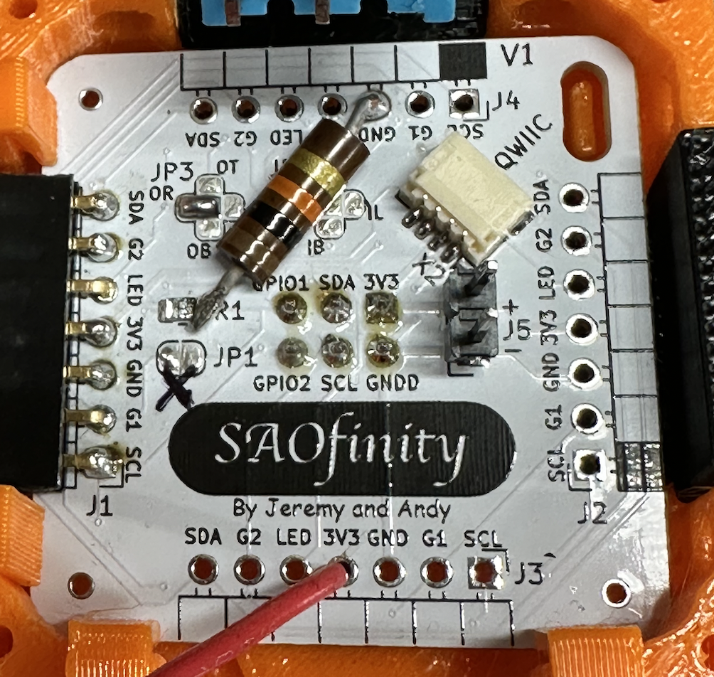
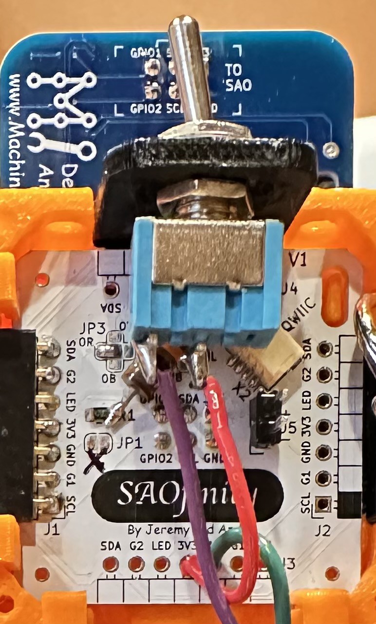
3. If you DO use a chunk of protoboard, then the glue is unnecessary and soldering the pins to the board will "sandwich" the connector in place. The recess in the grid makes sure it stays centered. The pins will be below the surface of the board but once you fill the holes with solder it will be solid.
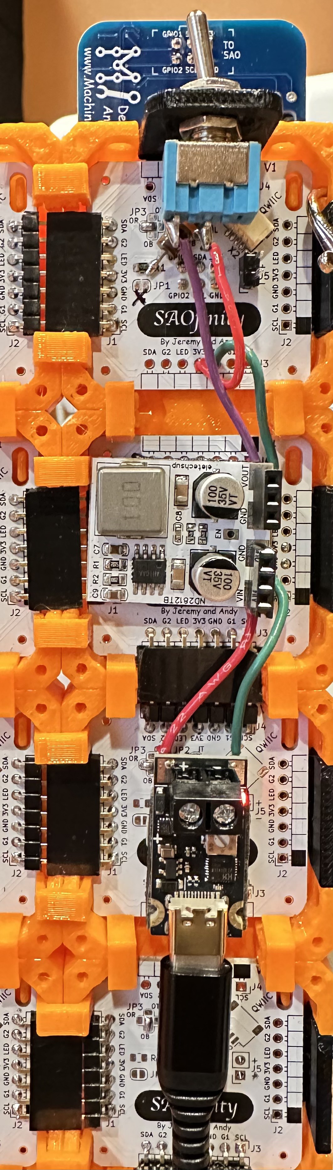
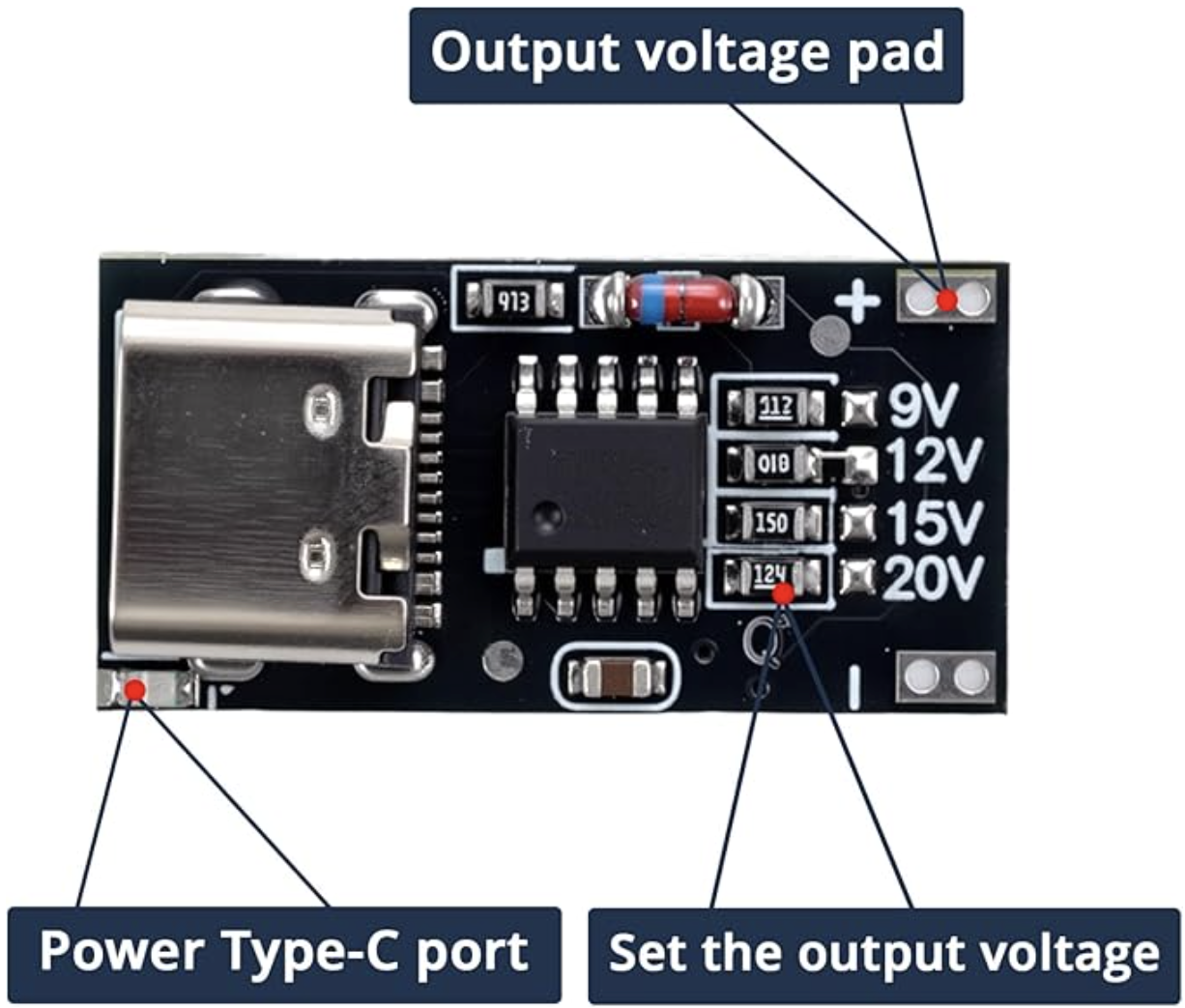
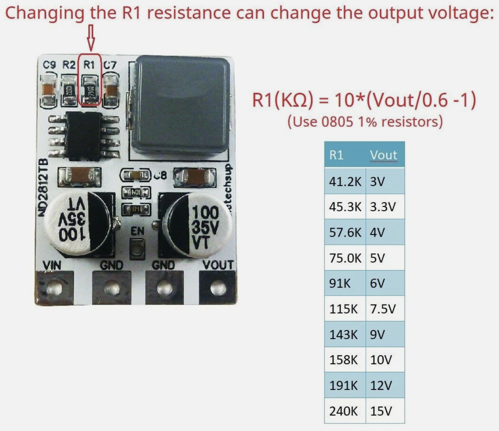
4. Wire up the power pins to 3.3 vdc. I simply used a step-down power regulator board powered from USB 5 vdc and daisy chained all the connectors. There are many options for power, just be sure to verify the polarity and voltage before plugging SAOs in.
This is a great explanation of SAOs and the pin-outs: https://hackaday.io/project/175182-simple-add-ons-sao
Summary:
There are other more elegant designs (https://hackaday.io/project/203082-sao-wall-tile) out there for modular displays that solve this problem. This aims to be the simplest and most likely to actually be built by someone interested without PCB design/ordering skills or financial commitment.
Next:
An optional custom snap in PCB with other features that hides in the back to make wiring grids easier. [In progress collaboration with @andygeppert.


 Alex Xia
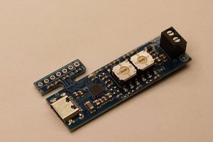
 MagicWolfi
 sidsingh
 Sagar 001
Nice