Close
0%
0%

OSUG: Open-Source Underwater Glider

A versatile autonomous environmental drone using a buoyancy engine

Similar projects worth following
There has been a breakthrough with low cost autonomous drones and as this capability has matured a wide range of hobby and commercial applications have developed. There are no affordable extended duration underwater exploration platforms and this project aims to address this need.

Utilising commodity hardware, 3D printed parts and an open-source autopilot, I aim to produce a low cost and versatile underwater glider capable of extended missions of up to weeks at a time. I hope that by having this platform available, it would reduce the cost of underwater projects for all, from hobbyists, amateur scientists to seafood farmers.

Contents

Interesting logs

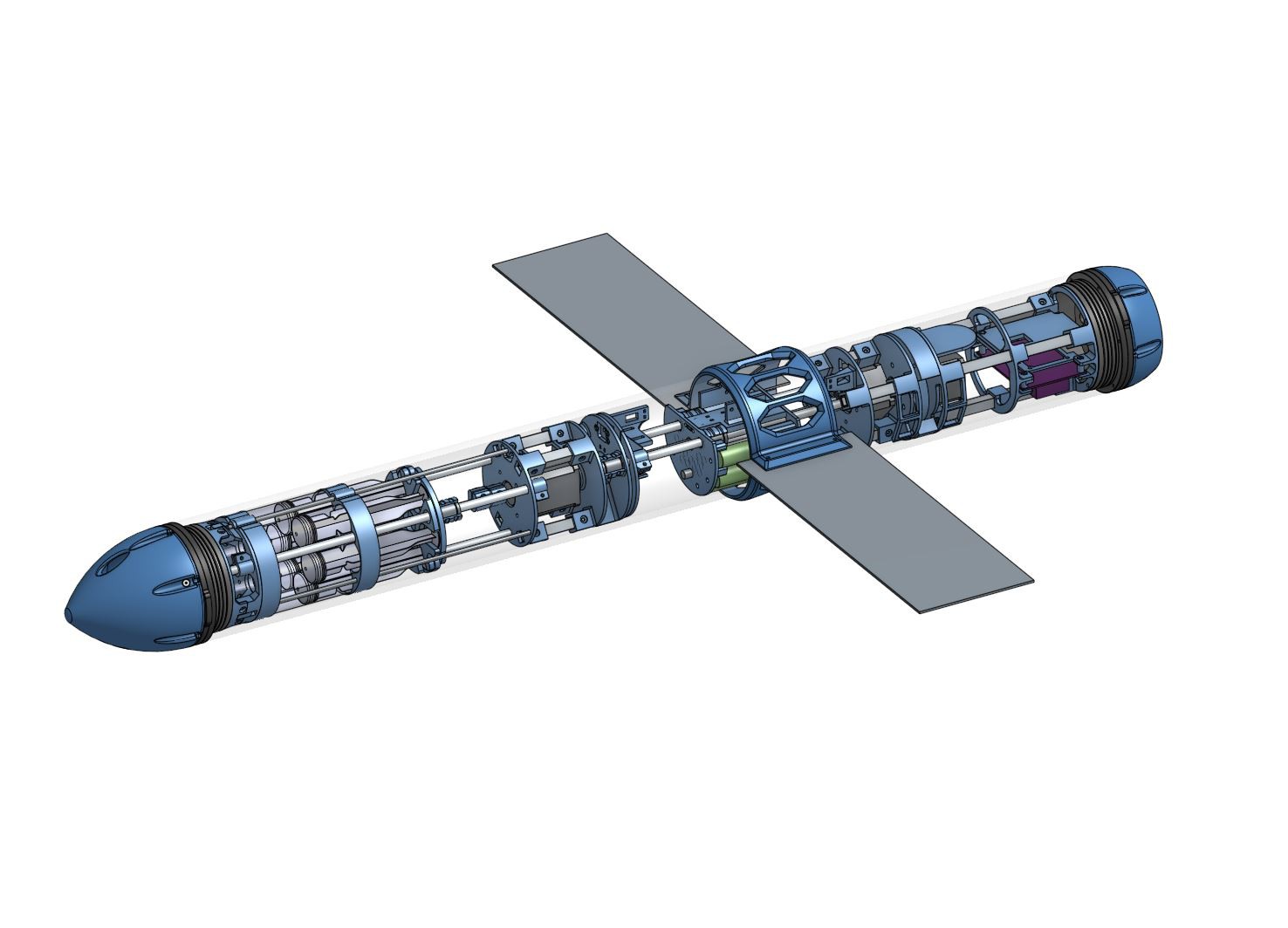
The CAD model

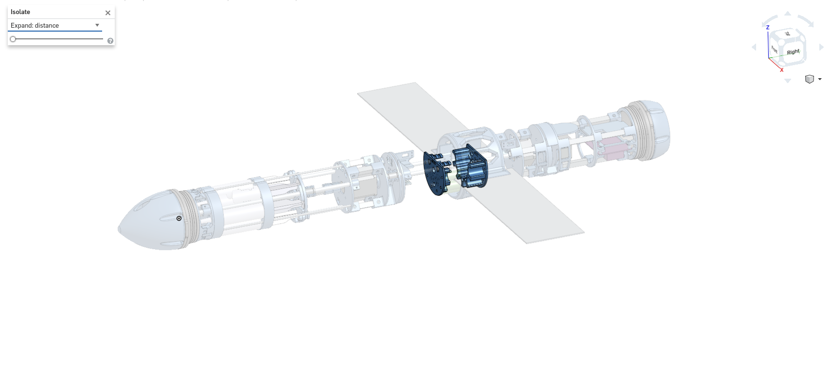
The model is viewable on the Onshape online platform here (requires webGL)


Video


Why a glider?

Traditional unmanned underwater vehicles depend upon active propulsion, limiting their range and runtime, making them unsuitable for long duration monitoring missions. Underwater gliders use a buoyancy engine to change the mass of the glider, allowing them to ascend and descend through the water. With power only being used to power the engine intermittently, gliders can typically run for weeks or months without recharge, making them ideal for environmental monitoring. Yet there are few commercial solutions available (and those that are available are very expensive) and even fewer hobbyist projects exist.

As underwater gliders travel slowly through the water, they disturb the surrounding water very little, allowing for accurate and reliable data recording. Underwater gliders are normally AUVs (Autonomous Underwater Vehicles) and can run a pre-determined route without requiring human interaction. Their low speeds and autonomy, combined with long battery life, make underwater gliders ideal for long duration, environmental monitoring missions, capable of recording dissolved gas levels, pH, temperature and optical sensing (for oceanic surveying and sealife recording).

This glider is open-source, with 3D printed components combined with readily available hardware, allowing it to be assembled for a low cost. Given the openness of the project, the project could be forked to produce alternative designs suited to particular scenarios. For instance; changing the tubing to aluminium to become a deep sea glider or using a unique sensor array for specialised applications.

I am looking to use the open-source Mission Planner combined with the Pixhawk autopilot platform, allowing the glider to be controlled using a standardised interface.


Example use case

With increasing interest in product transparency and traceability, environmental monitoring is becoming increasingly important; a kelp farmer could use the glider to monitor water conditions (temperature/pH/nutrition levels/pollution) during a season of growth and push the measurements to a blockchain. The kelp/seafood could be packaged with a QR code, which would direct you to a web frontend, presenting the conditions during the season of growth. The use of the blockchain and data insurance for measurement storage would remove the chance of measurement tampering, so the consumer would know both the conditions that their food grew in and exactly what they’re eating.

Above: A block diagram outlining the how the glider could be used for product traceability

How?

For the glider to move, the buoyancy engine takes in water and increases the density of the glider. When the density of the glider becomes greater than that of the surrounding water, the glider descends. The wings of the glider ensure that the glider goes forwards and the angle of attack can be altered to cause different glider characteristics. When at the bottom of the descent, the buoyancy engine will expel the contained water, making the glider more buoyant, causing it to ascend, moving forward again.

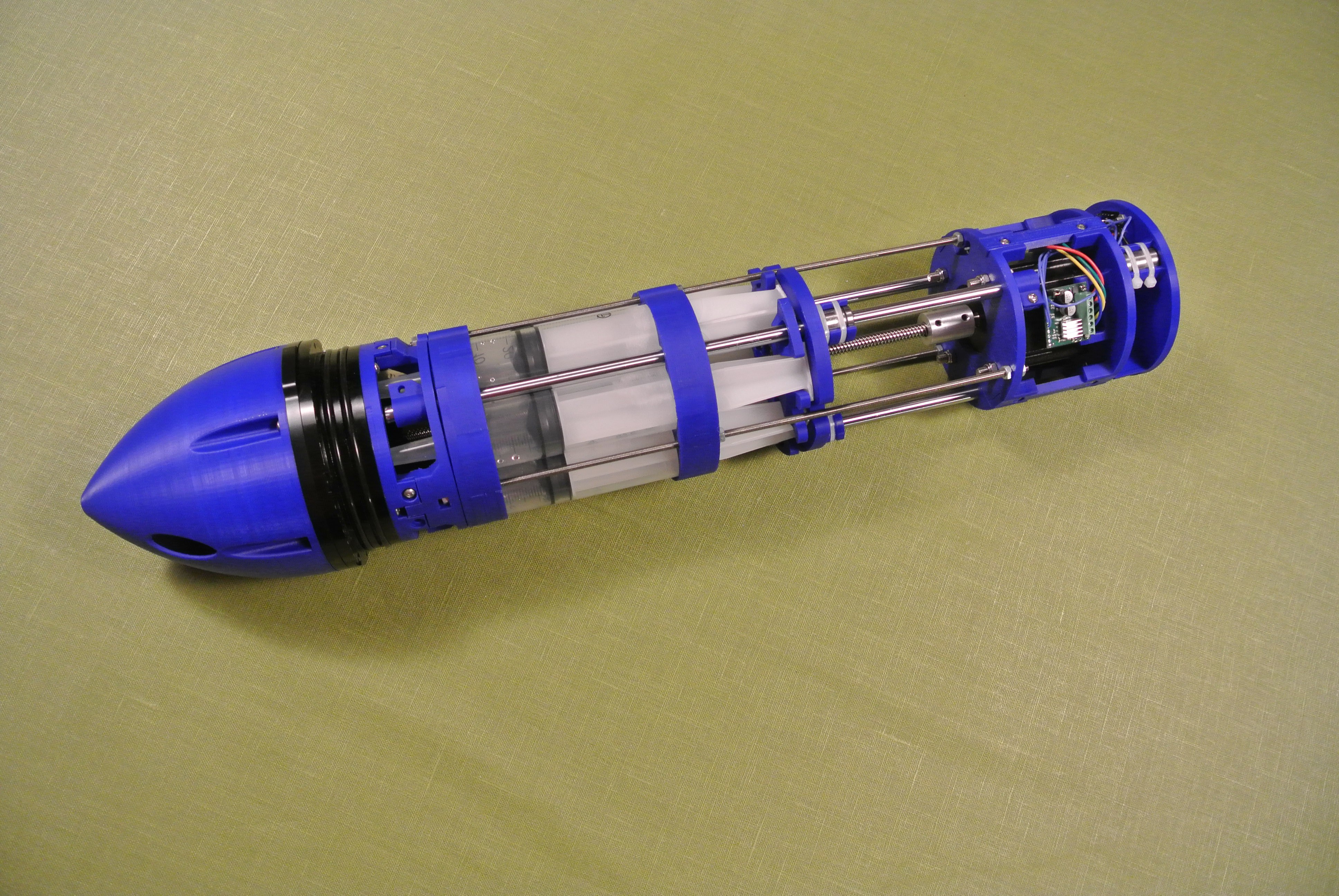
The buoyancy engine that I have designed uses an acme rod to move the ends of the syringes when rotated by a stepper motor, causing the plungers to take in water. When water is taken in, the volume of the glider remains constant, but the overall mass increases, therefore the overall density of the glider increases and the glider becomes less buoyant.At the centre of the glider will be...

Read more »

GNU GENERAL PUBLIC LICENSE V3.pdf

This project uses the GPL v3 license​ for all software related to the glider.

Adobe Portable Document Format - 78.20 kB - 10/21/2017 at 10:31

Preview

demo.ino

Arduino demo program for gliding forwards by descending and ascending

ino - 2.79 kB - 10/14/2017 at 23:02

Download

Calibration.ino

Arduino calibration program for calibrating the buoyancy trim of the glider

ino - 2.51 kB - 10/14/2017 at 23:02

Download

End_caps.pdf

Endcap drilling guide

Adobe Portable Document Format - 5.63 kB - 10/10/2017 at 22:58

Preview

Planetary_gearbox.scad

scad - 8.97 kB - 10/14/2017 at 22:30

Download

View all 54 files

  • 1 × Printed parts
  • 1 × Blue Robotics 4" tubing 1000mm The main tubing
  • 1 × MPU6050 Gyroscope/accelerometer
  • 3 × A4988 Stepper motor driver Stepper motor drivers
  • 6 × 18650 Protected cells Litium-ion batteries

View all 73 components

  • Pogo pin board replacement

    alexw03/07/2018 at 19:56 0 comments

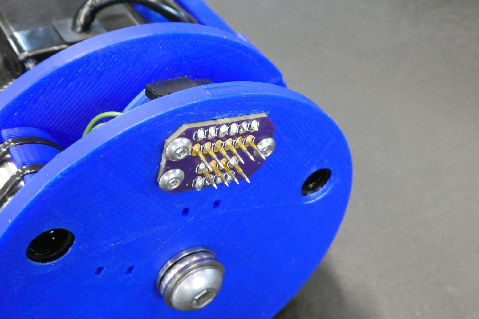
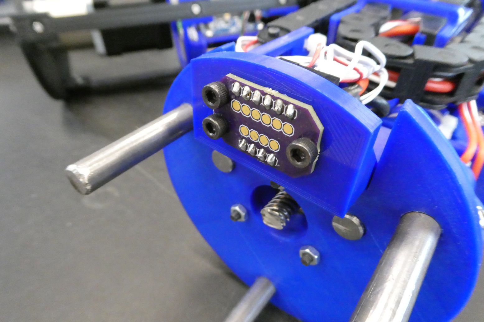
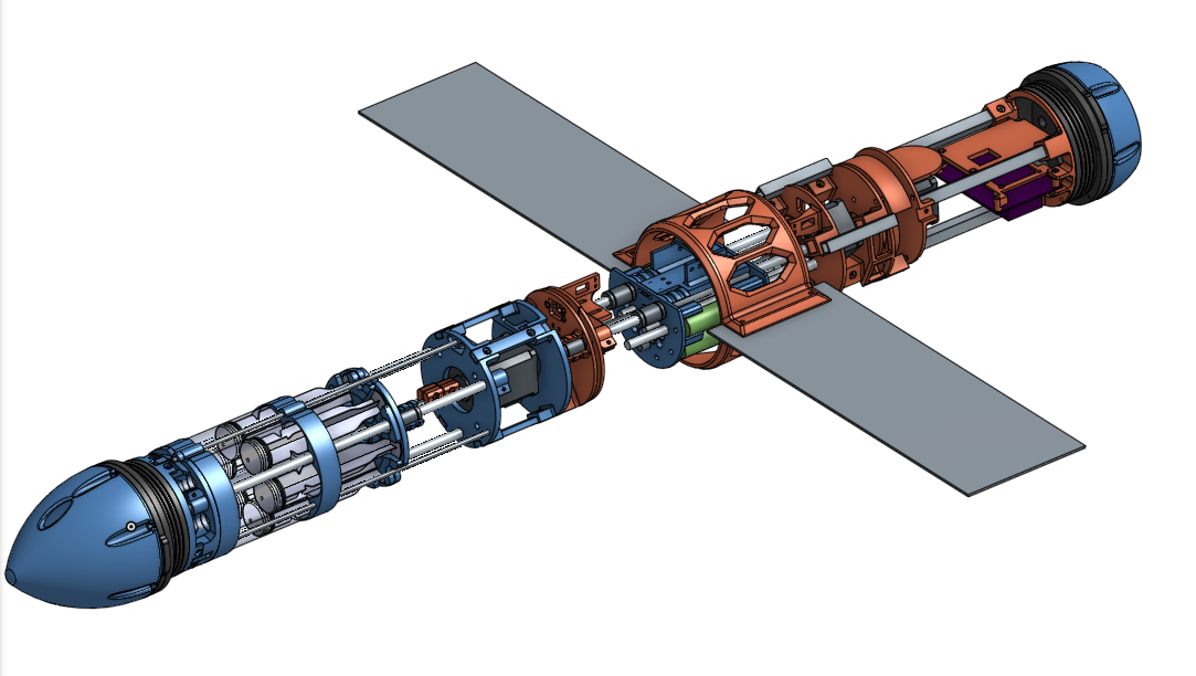
    The glider has 2 physical sections internally, the first is the buoyancy engine section and the second is the control boards and the pitch mechanism. The current design (below) uses pogo pins and a pair of boards to electrically connect the two sections, however this has two main downsides.

    The first problem with the pogo pins is that they use a spring mechanism in order to ensure a reliable connection, this causes the two sections of the glider to be pushed apart when the glider is assembled, which reduces the reliability of the connection. The other issue with this connection type is that the travel of the pogo connectors is only a few mm, which means that the rest of the glider must be aligned to within a couple of mm - the current solution to this is the sliding mounting bracket of the pogo connector PCB.

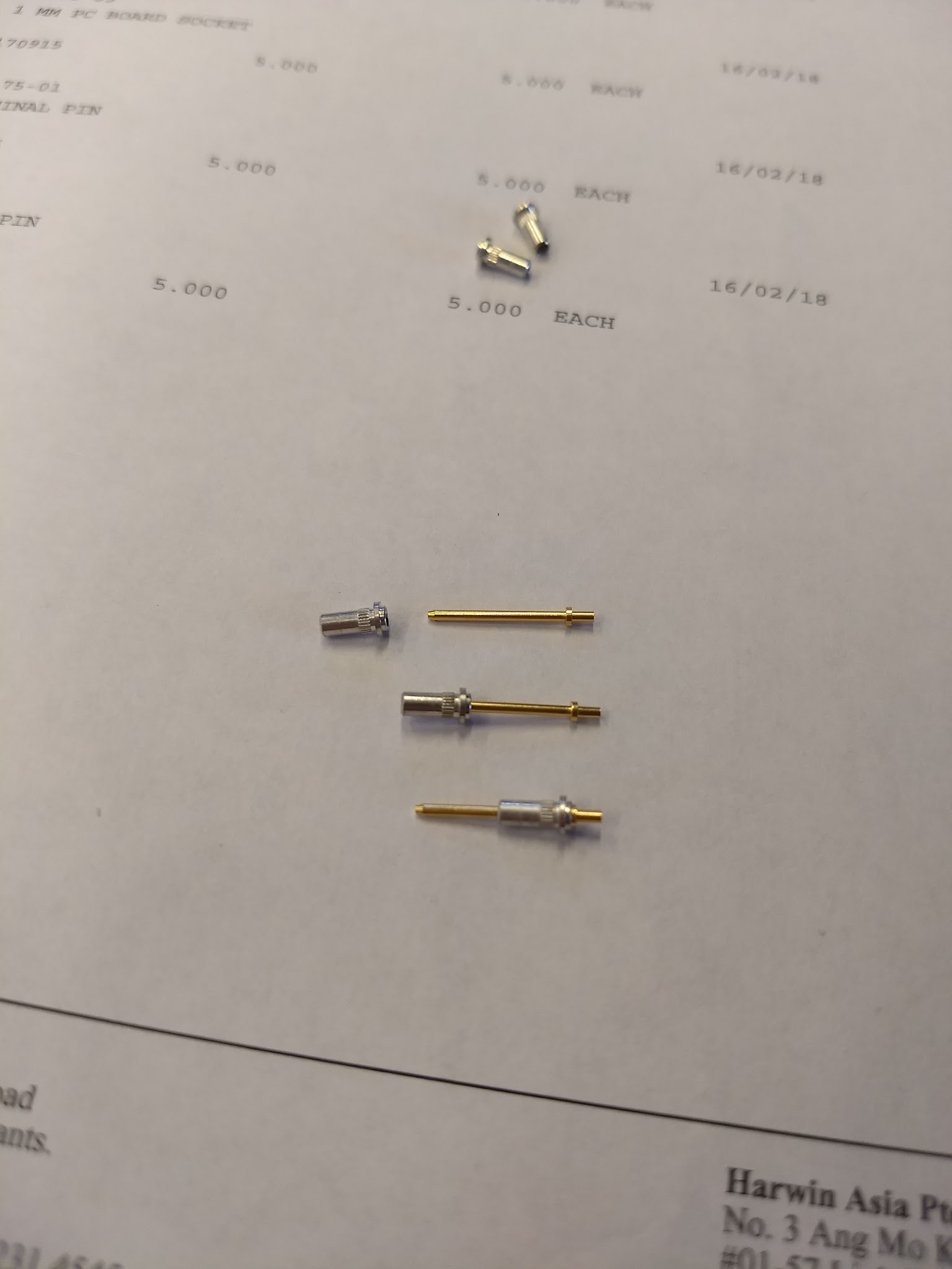
    With this in mind, the ideal connection would be one that does not have a spring contact and has ~10mm of travel. After having a look I was able to find the PCB contacts from Harwin that do exactly that, namely the H3169 and H2170 connectors.

    I ordered some sample connectors and they came through and were a perfect match for what I wanted, so I went ahead and purchased ~20 more connectors and designed some boards in Eagle for the two sides of the connector. Below is an image showing that the connectors in varying positions, all with solid electrical connections.

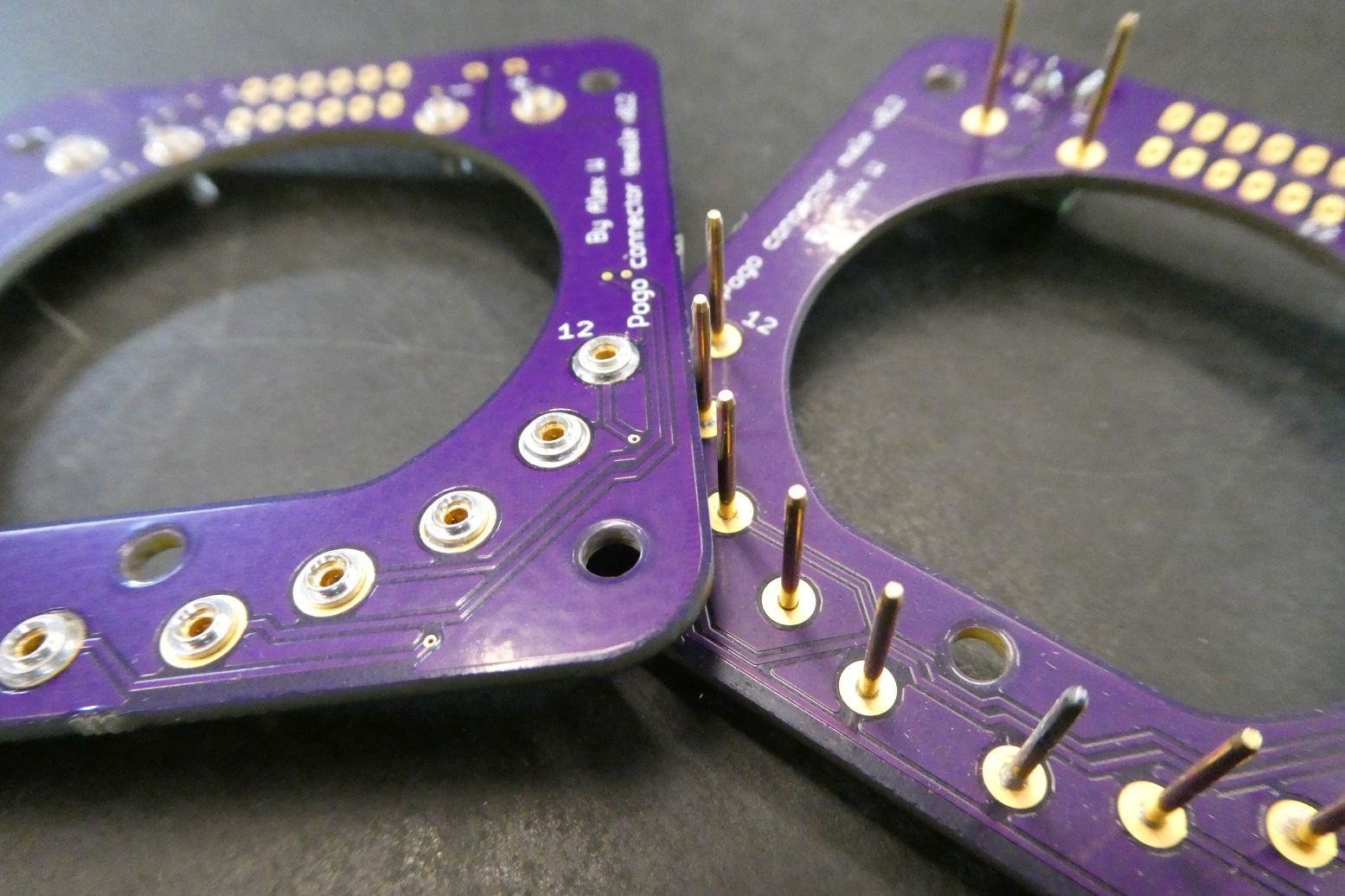
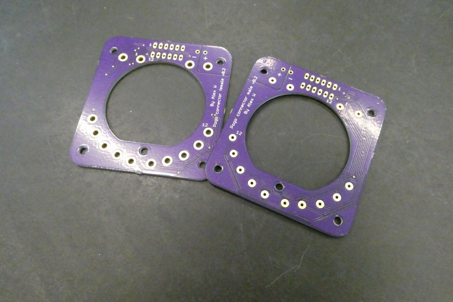
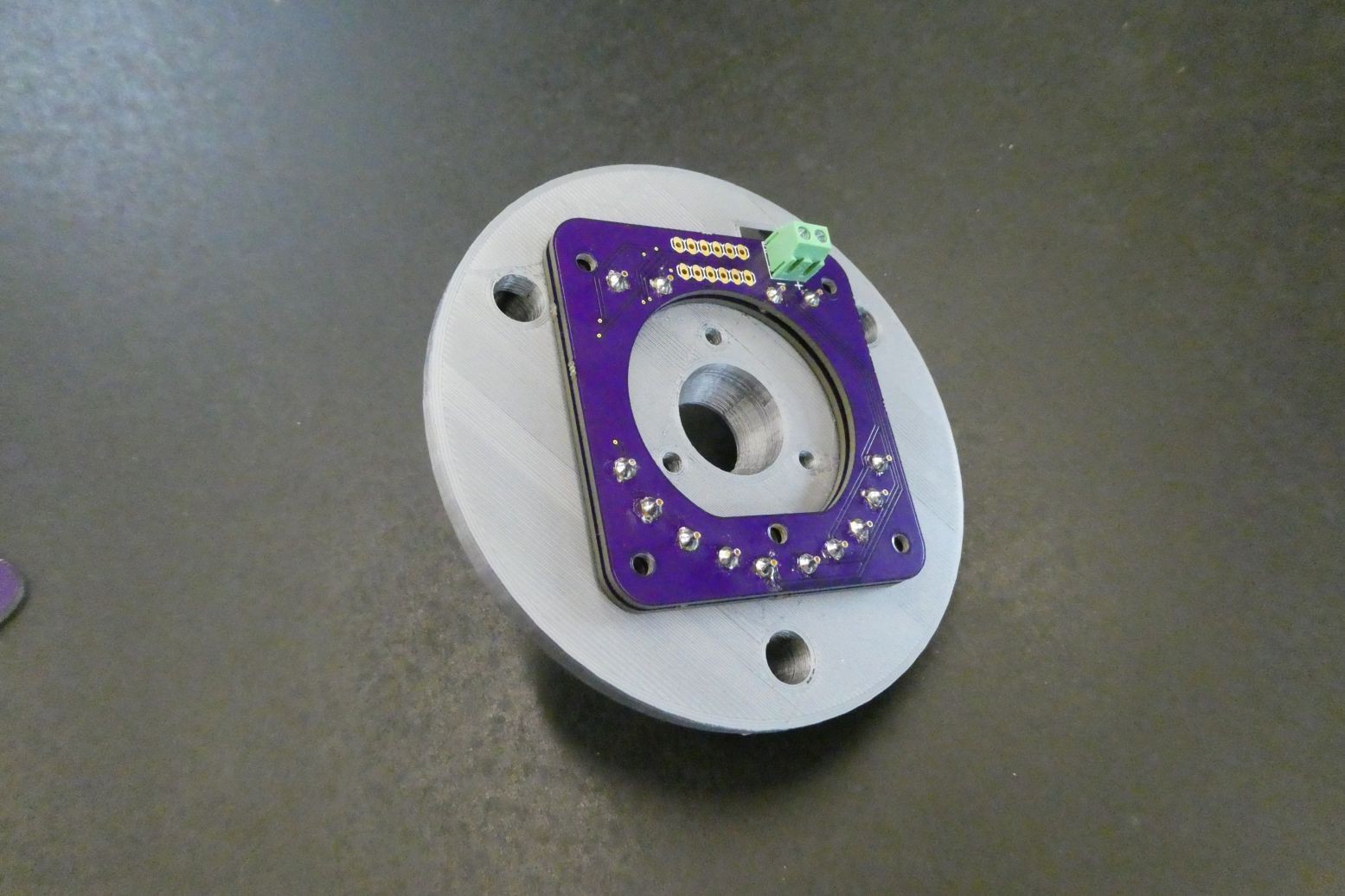
    I designed some updated boards for the ordered the PCBs through OSHpark and a massive shoutout to Drew (@pdp7) for providing great customer service and making sure I got my boards within a week. Below are some images of the boards and what they look like with the PCB connectors attached.

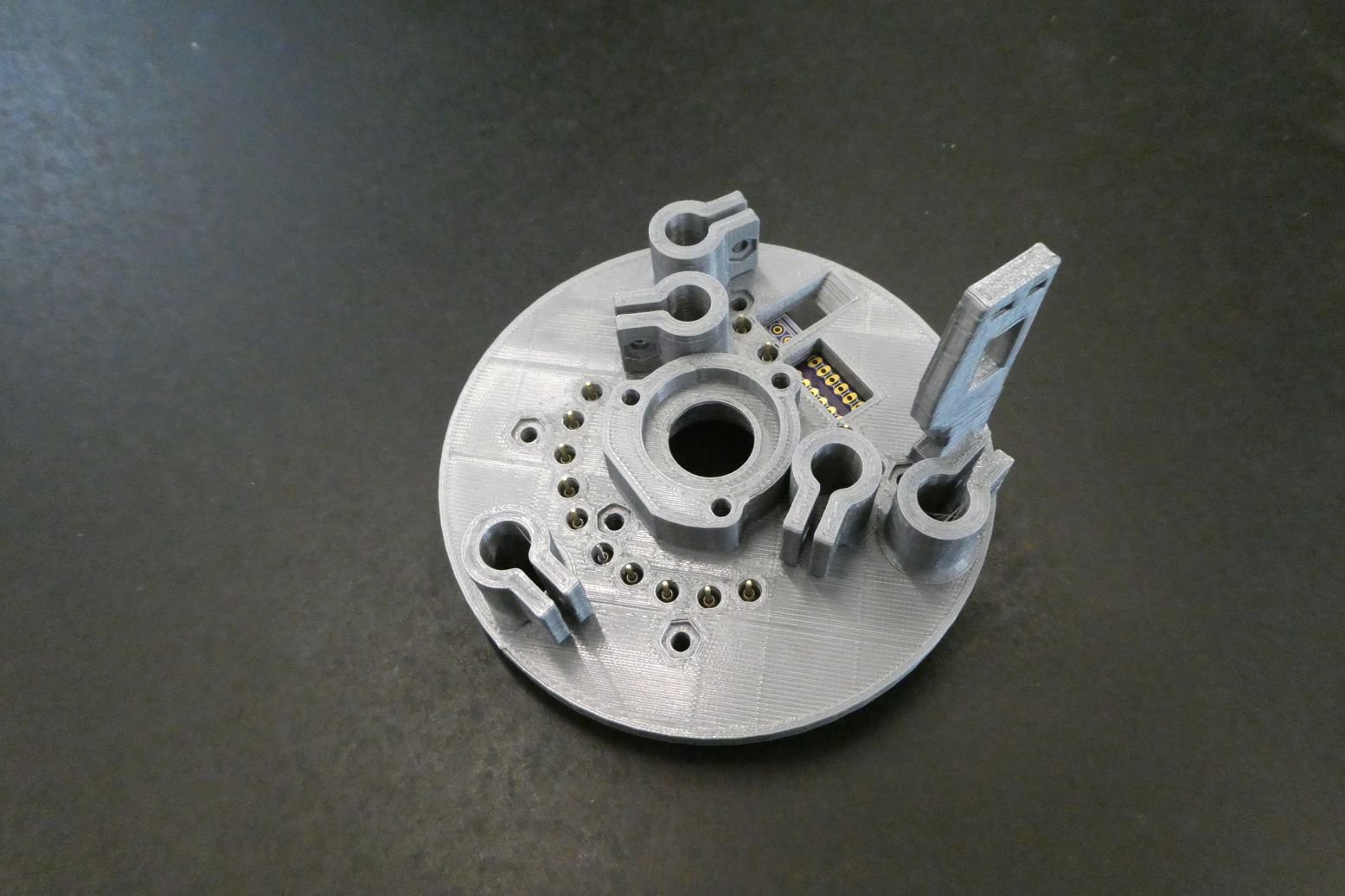
    This new configuration also more equally distributes the force of the contacts through the plate, as opposed to on the small section at the top. I designed and printed an updated PCB mounting bracket and you can see how the board fits in-between the alignment rods:

    Although using Onshape was an interesting experience, I am now transitioning to Solidworks for the design of the glider, but understanding that not everyone has access to Solidworks, I will still be providing the STL files so anyone can download and print the parts. The PCB files are also in the Dropbox development folder.

  • Assembled control board and backend update

    alexw01/26/2018 at 06:16 0 comments

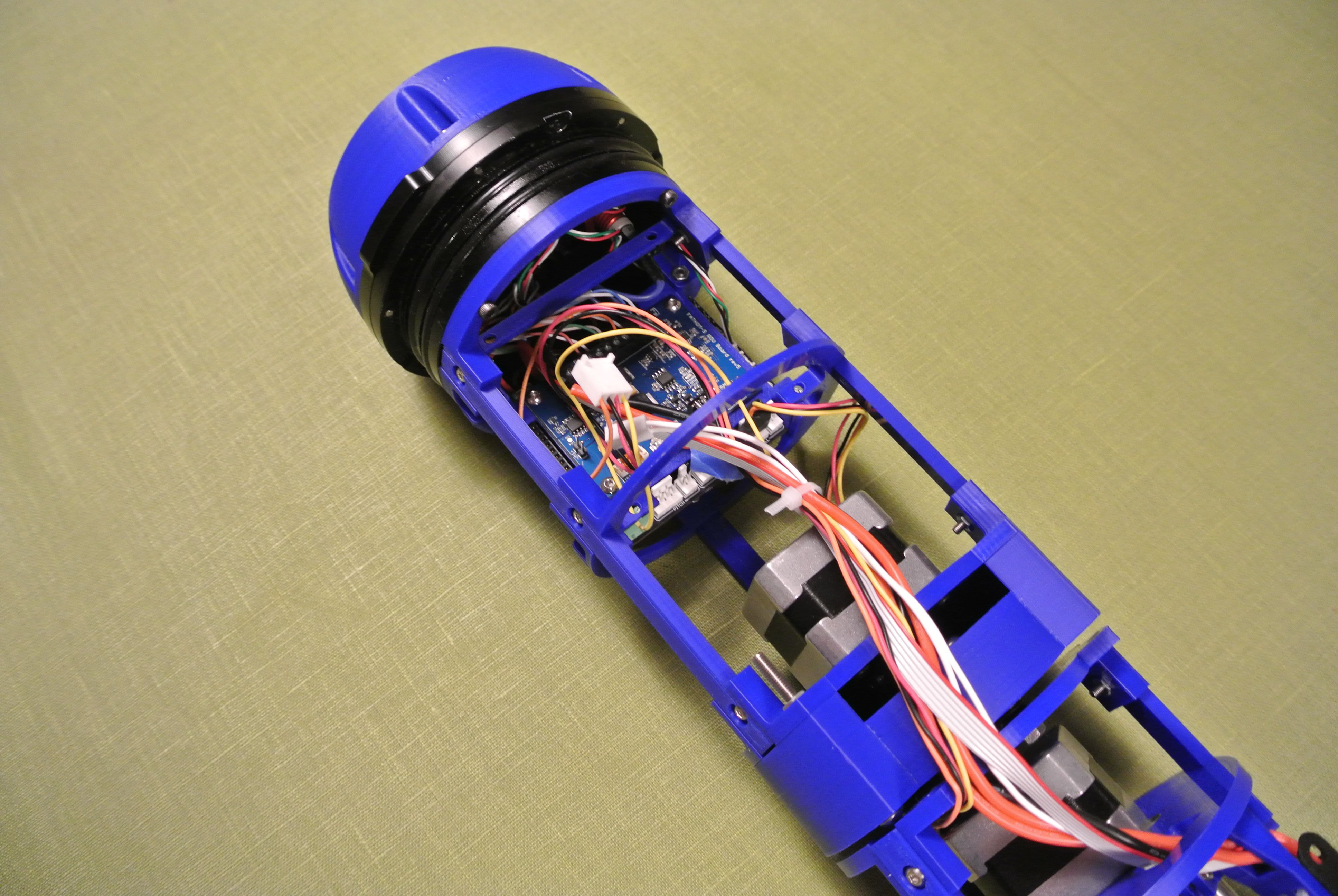
    The backend has been redesigned to be much more open for the new control board, and all the connectors are much more accessible. Also the control board has been lowered to allow for the integration of the Pixhawk 2.1 autopilot (the Cube took up too much vertical space previously). Most of the update to V3.1 has been completed but wiring still has to be completed. 

    The planetary gearbox has also been thickened to reduce play, but the latest version printed with too much of a bond between gears so I plan on reprinting this on a FORM 2 printer as this will be able to achieve a much better tolerance. I also changed the position of wiring past the planetary gearbox; previously the wiring ran on the side of the gearbox, which limited rotation, however the wiring now passes over the top of the gearbox and rotatory limits are symmetrical.

    Nothing noteworthy has occurred to the mass assembly, apart from the general thickening of printed pieces.

    The exterior components have been reprinted in 100% PLA and are not resin coated (The prints previously failed with 100% infill and let in water so had to be coated). However PLA still absorbed water – reports are a ~5% weight increase over a period of 30 days submerged, so I will look at printing the exterior components from PET-G.

  • Buoyancy engine update

    alexw01/26/2018 at 06:07 0 comments

    The last few weeks have been completely hectic and I have been unable to find time to document progress. I’m currently on a flight from London to Los Angeles to take up a residency at Supplygrame’s DesignLab to work on the glider, so I thought it would be a good time to do a few updates on the glider’s progress. I’ll split the update into two shorter sections, one for the buoyancy engine and another for the backend.

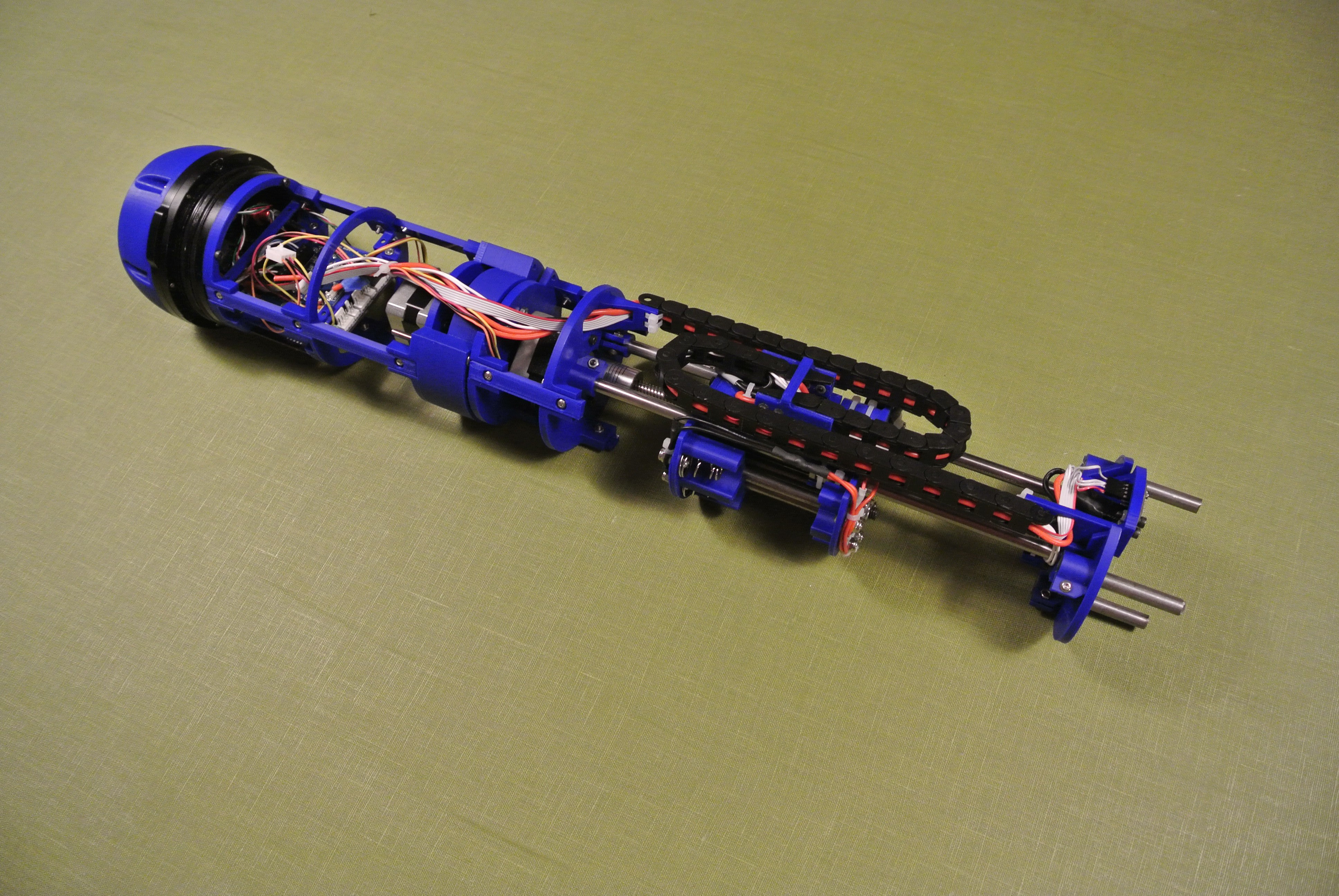
    Throughout most of the upgrade from version 3 to 3.1 I have been thickening components to improve structural strength, notably in the buoyancy engine. Below are two images of the engine, before and after the upgrade.

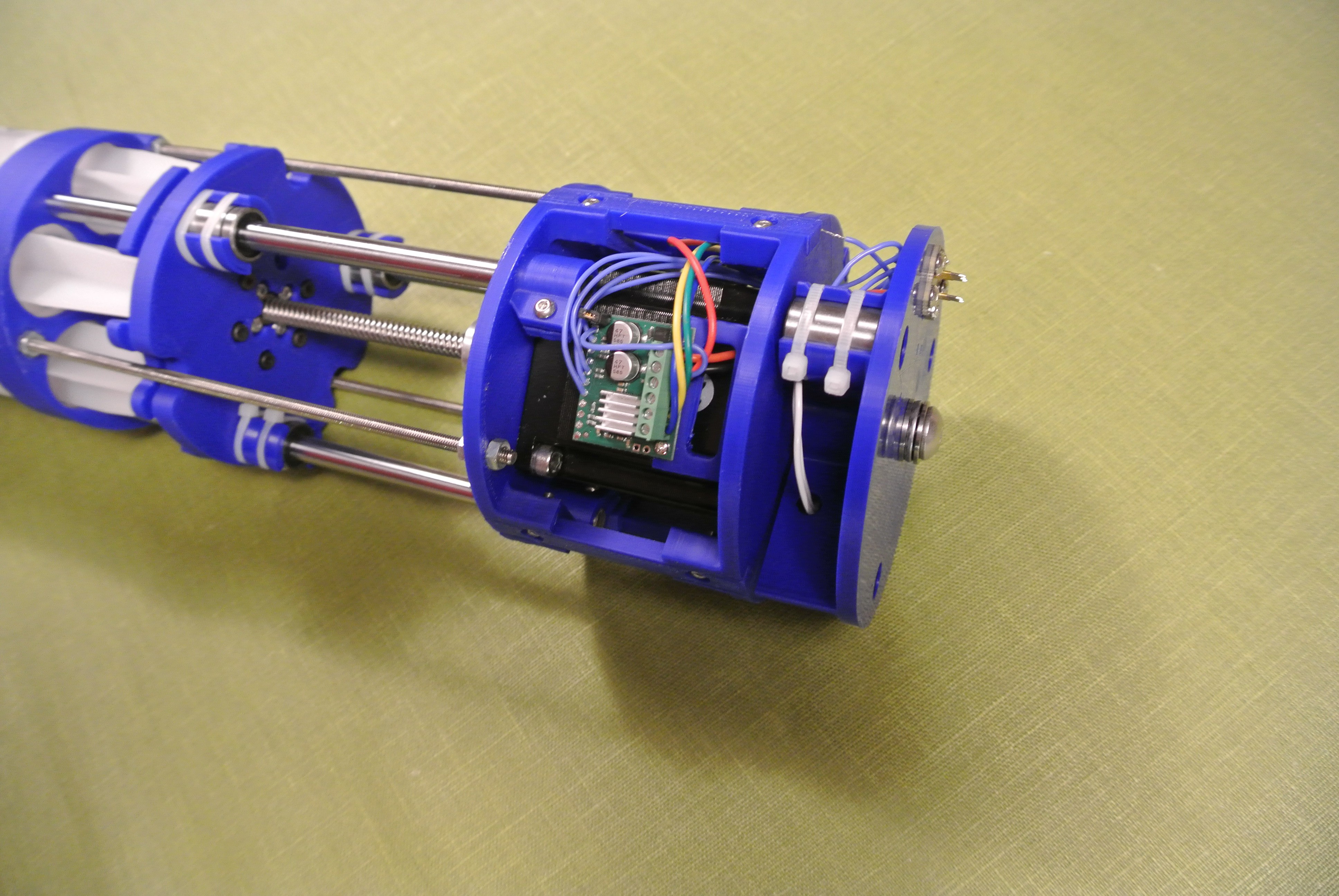
    Also note that the stepper motor has been upgraded from a NEMA 17 to a NEMA 23 motor, which runs at an equal power but has far greater torque. I have also moved the buoyancy engine stepper motor driver from the control board to mounted at the front of the glider, so that communication wires can be of a lower gauge and greater power can be delivered to the engine’s stepper motor. I have also upgraded the stepper motor from a A4988 to an AMIS-30543, as stated in my previous update. This allows for SPI communication to control the stepper motor more accurately and alter coil current on the fly.

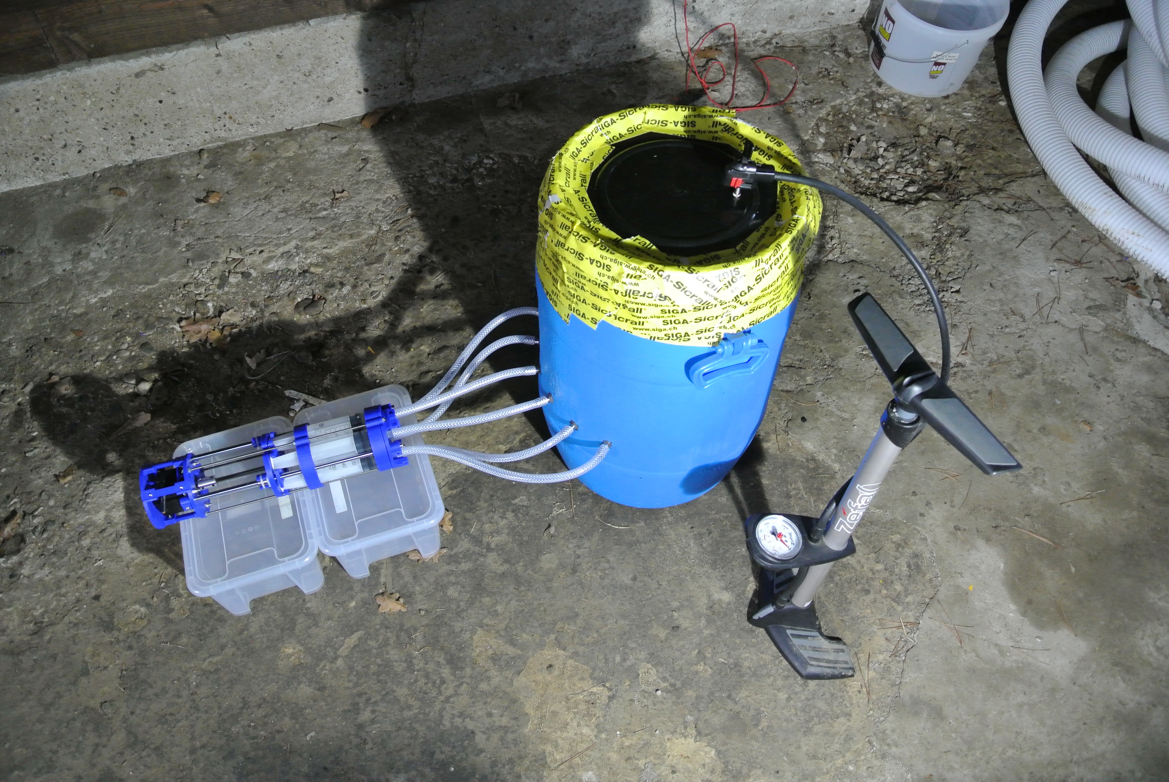
    All of the glider’s components in contact with water are rated to a depth of at least 100m, apart from the buoyancy engine. Therefore a depth rating of the glider can be determined by pressure testing the buoyancy engine (unless it can perform to a depth greater than 100m, which is almost guaranteed to be false). Hence I meant to test the buoyancy engine, however I was time constrained and air is a harder medium to deal with than I initially thought. Regardless, I’ll outline briefly the attempted testing method for anyone is interested.

    The idea was to connect the engine to a water barrel using the same tubing and connectors that are within the glider, to try and accurately represent the system used. The barrel then had a pump attached (it was a car tyre pump until a lack of suitable power source became an issue) to pressurise the water within the container until the engine failed. The engine would constantly pump as I believed the syringe seals were more likely to fail when moving. Unfortunately the seal at the top of the container wasn’t sufficient and even after multiple layers of airtight tape there were small leaks that would reduce pressure within the container. I was going to switch to using a silicone sealant to properly air-tighten the container but I ran out of time.

  • Control board v0.3 designed and ordered

    alexw01/10/2018 at 19:34 0 comments

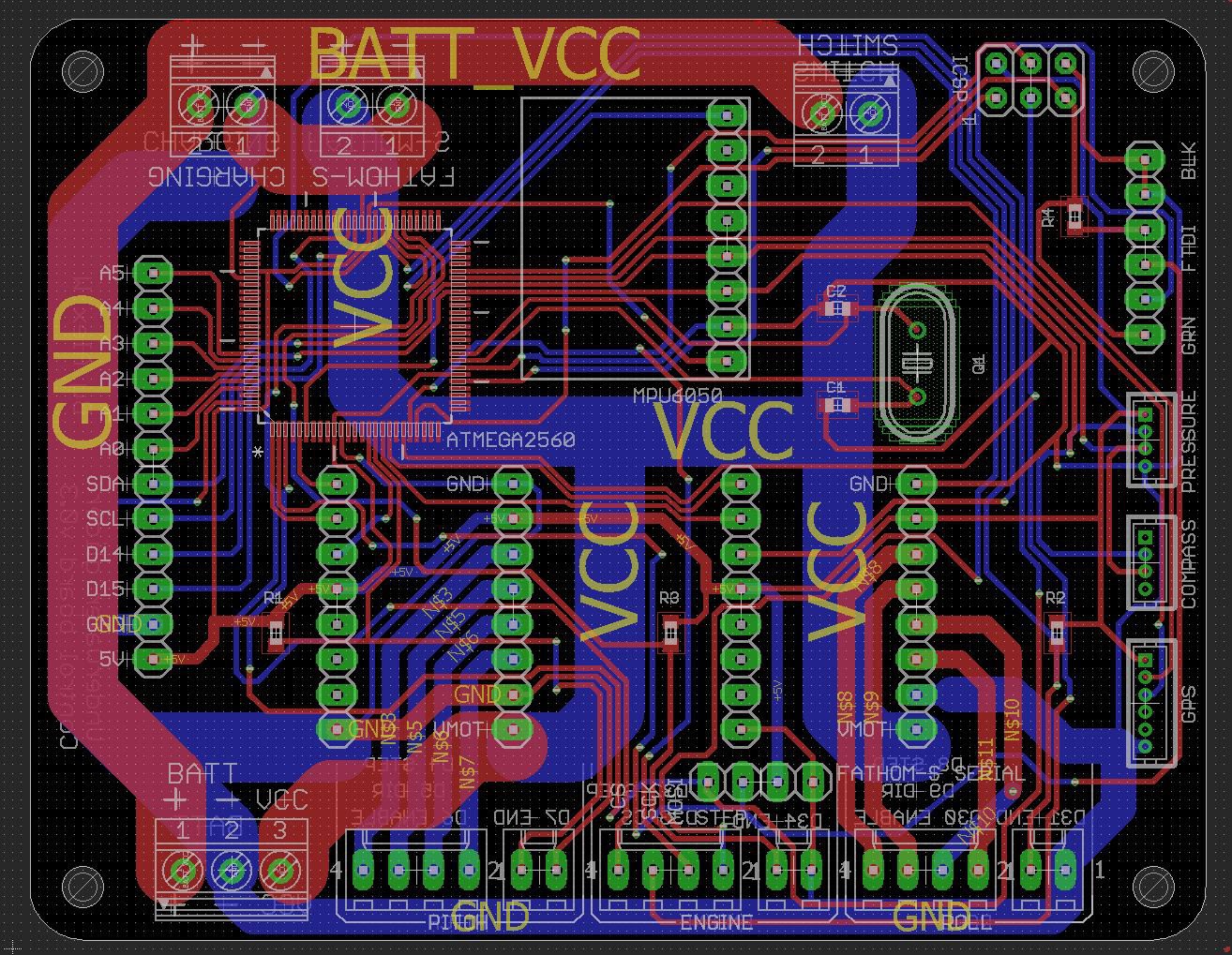
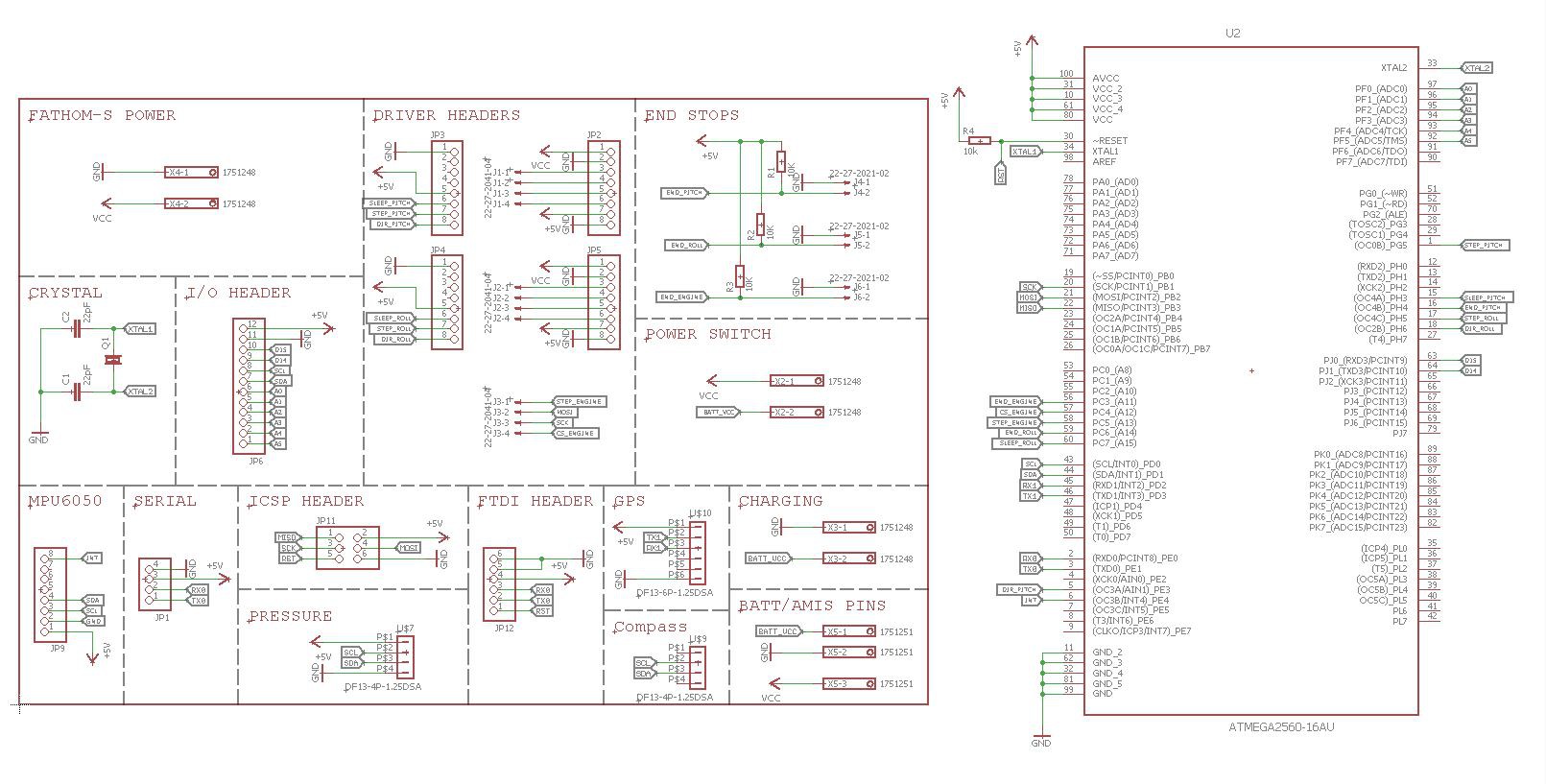
    Over the last few days I've updated the design for the control board, with two notable improvements. The first is the hook-up of the "enable" pins of the stepper motor drivers to the ATMEGA2560, so that it is possible to power down the drivers whilst not in use in order to maximise battery life. The other main update is the removal of the A4988 for the buoyancy engine stepper motor, instead sending signals to an AMIS-30543 stepper motor driver board, which is mounted at the front of the glider next to the buoyancy engine. The AMIS-30543 has a greater current capability (3A vs 1.8A) and uses the SPI communication to control current, sleep, etc. I made sure that the new PCB could fit lower down in the 4" enclosure, in order to accommodate a full Pixhawk 2.1 (the vertical height of the "Cube" meant that it previously wouldn't fit).

    The PCBs are being manufactured by OSHpark and I should have some assembled boards by mid next week. As usual, all design files are in the development DropBox folder, in the Underwater_glider/glider_pcbs/Control_board/v0.3 directory.

    Over the coming days I will be testing the buoyancy engine to potentially determine a working depth limit.

  • General update

    alexw12/02/2017 at 18:28 0 comments

    The last few weeks have been completely hectic with the Hackaday prize and sorting out university, things are only just starting to settle. It was really great to go over to the US for the Supercon, I enjoyed meeting everyone and I appreciate all the useful feedback I recieved. As part of winning the Hackaday prize, I hope to take up the residency at Supplyframe's DesignLab in the New Year and this will give me a three month period to focus solely on the glider. 

    Over the coming weeks I'll be updating the design of the glider from v3 to v3.1, a version of the glider that I believe will be suitable for alpha kits for real world testing. During the glider update I will be testing various parts of the glider to ensure reliability and to get some performance figures.

    The main testing will be on the buoyancy engine, so I have a depth rating and an understanding as to how well it performs. As the glider/buoyancy engine is quite large it will be hopefully be done in a modified water tank with a car pump attached. A camera on the inside of the tank will be used to monitor the state of the buoyancy engine to make sure there are no leaks, etc.

    For those interested in kits, I appreciate the support and I am aiming at finalising the design so that I can come up with a finalised cost. I looked at printing the parts using 3D printing services but it is more effective print the parts myself, so I have purchased a CR-10 printer for printing sets of parts.

    You can view the live development CAD of v3.1 here. Red is v3 parts and the blue parts are parts that have been updated to v3.1

  • Future testing and to-do list

    alexw10/18/2017 at 17:18 0 comments

    As the third generation of hardware is completed for the glider, it has reached a stage where it needs to undergo testing to find the capabilities of the glider. Below are a few tests that need to be performed on the glider and a brief explanation of each test:

    • Testing of the buoyancy engine system to determine a depth rating of the glider - All of the exterior components of the glider (end-caps, switches, underwater plug etc) are rated to at least a 100m depth, whereas the buoyancy engine does not currently have a rating. A pressure test of the buoyancy engine (likely destructive) will determine the overall depth rating of the glider. (The test would be to attach all the syringes to another set of syringes with a plate on top, weight would be added to the plate until the stepper motor cannot move the weight or the seals break, if the former, the stepper motor will be upgraded.)
    • Perform reliability testing of the buoyancy engine under pressure to make sure that the movement systems do not become stiff. Minimum of 24 hours.
    • Perform underwater tests with the glider running at different glide angles, used to determine the best angle of attack for different missions (steeper = faster, shallower = greater endurance)
    • Perform extended endurance/range testing as the current endurance/range of the glider is calculated by extrapolating out current data (42 hour running battery life at ~0.2m/s = 28km). Once a depth rating of the glider is achieved, the glider can glide to a greater depth which will mean that it reaches a greater speed and spends less of its time transitioning between gliding states, so the range of the glider will increase.
    • As I have only been able to test the glider in small areas of water, it has not been possible as of yet to demonstrate the turning of the glider clearly, so the glider needs to be tested in a larger body of water.

    I have also put together a to-do list to get the glider to version 3.1. This list is primarily hardware and does not include any to-do points concerning the Pixhawk and automated waypoint navigation system. An up-to-date version of this to-do list will be kept in the dropbox folder.

    Printed components

    • Change acme nut to an anti-backlash nut to prevent acme screw wear in the long term
    • Redesign wing mounts to have a slight dihedral so that the glider is more stable underwater
    • Choose a standardised micro lever switch and use screws as opposed to hot glue
    • Make the planetary gearbox thicker to reduce play/wear
    • Redesign the wiring routes past the planetary gearbox
    • Redesign the Pixhawk mounting plate so that the board can be more easily placed/removed
    • Try and fit all of the external ballast bars internally, to reduce drag etc
    • Change all roll components to a diameter of 98mm, as opposed to 100mm (to reduce friction inside the tubing)
    • Strengthen endcap mounts to prevent bowing
    • Strengthen engine bearing fastener to prevent bowing
    • Redesign motor/acme clamps to increase strength
    • Upgrade buoyancy engine motor to a NEMA 23 motor if required
    • Make pogo PCB mounting plates thicker to prevent bowing

    PCB

    • Hookup the “enable” pins of the A4988 boards, so that you can power off the stepper motors when they’re not in use to increase battery life
    • Hookup a greater number of the unused I/O pins to header pins to increase the number of additional sensors, etc. that can be used
    • Reposition the A4988 stepper motor drivers so that you can access all of the potentiometers without drilling into the aluminium tubing
    • Use the Blue Robotics switch as switch to a relay for the main power control - the switch is potentially getting to the edge of its current capability

    General

    • Think of an alternative to aluminium tubing, to reduce variability in reproduction
    • Upgrade the hotend of the printer and print all components in polycarbonate
    • Apply for Sparkfun funding for their dissolved oxygen sensor
    • Contact Onshape on their forums with review/feedback - global parameters or feature folders are the main suggestions...
    Read more »

  • Build instructions and possible kits

    alexw10/15/2017 at 09:27 13 comments

    Full instructions for the glider are now completed, with a level of detail that if you're able to assemble a RepRap kit, you should be able to assemble the glider. The only tools required are a 3D printer, soldering station, dremel and then various handtools such as hacksaw/allen keys etc.

    With the Onshape CAD model, you are able to duplicate the model and adapt the hardware for your own requirements (such as adding a front mounted camera) - this glider is designed to be a hardware platform for others to use/adapt, not a project with a fixed use case.

    If there is interest, I may look into the possibility of putting together a few kits containing all parts/3D printed components that are known to work together so you can assemble the whole glider in a couple of weekends.

  • Assembled CAD model (and onshape features)

    alexw10/10/2017 at 10:45 0 comments

    I've finished assembling the Onshape CAD model for the third generation of the glider. It can be viewed here. There are a couple of features of Onshape that make visulisation of the model/sub-systems easier. You can hide objects which completely removes them from view (Useful for the tubing as it then allows you to select internal components). You can also isolate a component (or multiple) which makes all other components faded and makes it very clear as to what the individual components look like etc.

  • Final(ish) third generation hardware

    alexw10/07/2017 at 16:13 0 comments


    I have gone over the glider CAD model and I have changed the parts so that no post processing is required (unless I've missed something).

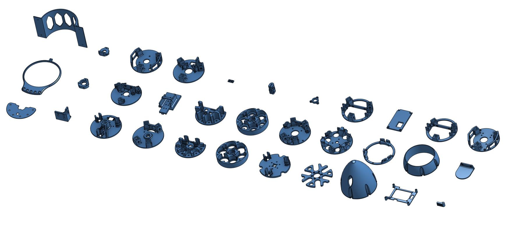
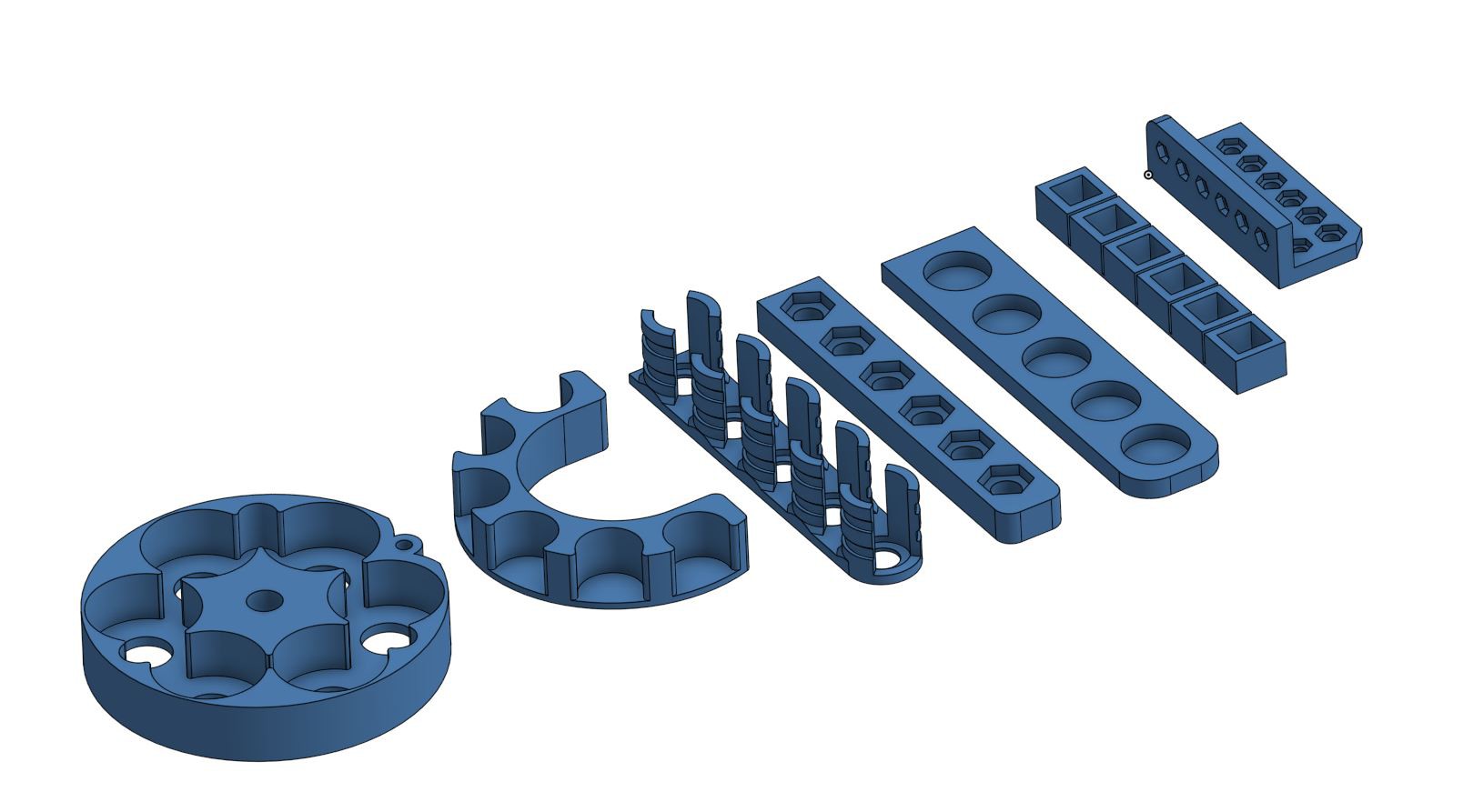
    Within the Onshape model, the test prints should be printed first and they are used to select values for the component variables.

    I am aware there is currently a lack of instructions for the third generation of hardware but all the images of the assembly can be found in the dropbox folder.

    I should update the project page soon with full instructions for the assembly of the glider.

  • Ascending and descending underwater

    alexw09/22/2017 at 21:54 0 comments

    Just a quick update regarding some testing of the new hardware: I recently had access to a pool and I was able to test the glider's new hardware in deeper water. There is currently no control software onboard, so the glider is dead reckoning using set timer delays (4 seconds down, 4 seconds up). The pitch mass is not varied during the duration of the filming. The angle of attack is currently quite steep, but this will be optimised as a PID algorithm becomes integrated. The tether at the back of the glider is only there for remote programming, which made it quicker to modify timings whilst the glider was in the water; the tether did not need to be attached whilst it was performing this gliding sequence.

View all 32 project logs

  • 1
    Build notes
    • Given vibrations throughout the glider due to the stepper motors, I would recommend using threadlock or locknuts throughout the build.
    • Most of the parts are parameterisable and should be adjusted to your printer. However, there will be parts of the prints that require a small amount of sanding/drilling to make sure that holes are the correct size.
    • If there are any errors with the build instructions or CAD components (or if you have any CAD part name suggestions - I lost imagination after a while), leave a message and it shall be fixed as quickly as possible. All suggestions are very welcome.
    • On the Hackaday page are a set of STL files with custom values for my particular printer. While these may work for your printer, it is suggested to print the files with custom part variables for your printer, determined by printing a set of test pieces as outlined further on in the instructions.
    • As the Hackaday’s project editor is slow to work with, I made all of the instructions on a google docs documents. When I ported the instructions across all the images became slightly out of proportion and there are too many images to manually change them all. You can view the images in the correct proportions if you click on the image. You can also view all of the images on the Dropbox image link
  • 2
    Preparation of PCBs

    Some board services leave tabs on the PCBs, so you can remove these and sand the edges of the board smooth.

  • 3
    Soldering SMD components

    This step uses hotplate surface mount soldering, a more detailed example of this technique, including video, can be found here at hobbytronics.

    Using a non-food hotplate, heat the PCB slightly, this allows the solder paste to be applied more thinly as it is less viscous and comes out of the syringe more easily.

    Apply the solder paste to the SMD pads, as shown highlighted in red. Use the tip of the solder paste extruder/cotton buds/kitchen towel to remove excess solder paste from the pads. Surface tension will cause the solder to go onto the pads on the atmel chip, so don't worry about connecting them all at this stage.

    Using tweezers, place the SMD components onto the board. R1/R2/R3/R4 are 10K‎Ω resistors and C1/C2 are the 22pF capacitors. Only the atmel chip is orientation specific, so make sure that the alignment dot on the chip lines up with the star on the board. Make sure that the atmel chip's pins line up with the pads on the board.

    In order to form the solder joints, heat the hotplate up to its maximum setting and watch the pads closely. When the solder paste gets near the required temperature, it will turn into a liquid, and it will then gain the silver solder appearance as it continues. Make sure that all of the solder joints have been formed before removing the board from the heat.

    Some of the pins of the atmel chip will have bridged, so use desolder braid to remove the excess solder causing bridging. Use a multimeter continuity tester to check that no pins are connected to the pin next to them.

View all 25 instructions

Enjoy this project?

Share

Discussions

mnm.76675 wrote 02/22/2024 at 20:15 point

Hey!
I wanted to ask which GPS sensor you have used here. I am unable to find details about itin the provided data.
Thanks!

  Are you sure? yes | no

Em wrote 02/21/2024 at 12:46 point

Hiya everyone! Does anyone know if the inventories in underwater_glider/Glider_PCBs/Component_list.ods and underwater_glider/part_list.ods contain all the required electronic components besides the arduino and battery system? I'm having difficulty reconciling the main page 'Instructions' with 'Components'. Thanks for your help! 

  Are you sure? yes | no

Benjamin James wrote 03/09/2023 at 18:33 point

I am headed from San Francisco to Dreamspace in Sri Lanka, where they are attempting to monitor inlet water quality with their students. They have built a version 1 and are now working on improvements. If anyone would like to chat about their build or ask questions about this new version feel free to message (here ideally, to have a community convo, or @JamesLearns on Twitter)

  Are you sure? yes | no

Roarou wrote 11/16/2021 at 13:35 point

Does anyone have a backup from the git? It seems like the page is not available anymore and I would need it for a student project.

  Are you sure? yes | no

RodediahK wrote 12/06/2021 at 21:34 point

I believe this is it.

https://github.com/dreamspace-academy/dreamspace-underwater-glider/tree/master/images/printing-parts

  Are you sure? yes | no

mr.free.k98 wrote 06/12/2021 at 07:48 point

hi dude, i need your help dear

can you tell me the weights of your gliders part? like batteries and buoyancy tanks weight and sensors? ill be very happy if you kindly tell me, alirezaa.jafari.98@gmail.com is my mail address

  Are you sure? yes | no

maciejko.koba wrote 05/18/2021 at 22:14 point

Hi, is it possible to get an assembly Glider v3 file maybe? I need it for my diploma work.

  Are you sure? yes | no

tron wrote 10/30/2019 at 01:41 point

Anyone on this post willing to build a full scale model and if so for how much?

  Are you sure? yes | no

thamhut wrote 07/02/2019 at 15:32 point

Great! My son like it

  Are you sure? yes | no

raiss wrote 03/22/2019 at 08:11 point

Hi Alex,

I find this project very interesting. I'm currently an engineer student doing my last internship in Malaysia and my main mission is programming an underwater glider with arduino. However i'm not very familiar with programming. Is it possible to have an access on some code that you used on this software to create the movements of descents in depth and rising on the surface of the glider for example. This could allow me to better understand and get on track.

 I would be very grateful to you.

  Are you sure? yes | no

topbloke23 wrote 03/22/2019 at 13:41 point

try looking

 harder....

  Are you sure? yes | no

blakebenn wrote 09/13/2018 at 19:42 point

Hi Alex,

Amazing project! I'm using your glider as a base model to build an AUV purposed for coral reef monitoring (for my senior project). Would you be willing to post the updated Solidworks parts? Have they already been posted?

Thanks,

Blake

  Are you sure? yes | no

alexw wrote 09/20/2018 at 08:11 point
Hi, sorry for the delay, the solidworks files are in Underwater_glider/Glider_version_3.3/Solidworks directory of the dropbox, a few of them are direct imports from onshape, so the modelling is embarrassing and needs to be redone... Unfortunately other activities have taken up the vast majority of my time and then some, so I've not been able to work on the glider recently - let me know if you find the solidworks files correctly.

  Are you sure? yes | no

˙˙˙ɹǝʌo ǝɯ dılɟ ʎǝɥ wrote 06/28/2018 at 17:40 point

Interesting project! Has anyone costed out the BOM for a ballpark estimate of what it would take to buy all the parts?

  Are you sure? yes | no

alexw wrote 09/20/2018 at 08:13 point

Heya, I believe I posted a ball-park BOM price a while back, it's about $1500 if I remember correctly, with about $800 of that being Blue Robotics parts

  Are you sure? yes | no

Gabriel wrote 04/13/2018 at 14:37 point

A Masterpiece.

I think this glider might benefit from having proper "airfoils" / waterfoils?? shaped wings, instead of just a flat surface. 

I would also suggest looking at adding a Canard as i believe it might improve the glide/sink ratio. Canards have some "flight" properties that might be beneficial to a design like this.

I would try a delta wing (like the Concorde) as well just for kicks. - lots of surface area!

  Are you sure? yes | no

Modzer0 wrote 04/16/2018 at 15:52 point

Large surface areas like that are counterproductive underwater. The amount of drag created makes it less effective than smaller surfaces. When I was working on and building AUV/UUVs we spent a lot of time modeling to optimize forward propulsion vs energy usage.

Open water is also a very dynamic environment. It needs as much streamlining as possible to stay on course or it will just get tossed around even more by currents and wave motion.

  Are you sure? yes | no

Lee Djavaherian wrote 04/11/2018 at 19:42 point

Alex, (I apologize in advance for the lengthy comment), I've been wanting to compliment you on your project but hadn't gotten my latest project to a near-finished state until now (just created my #TrillSat project page last Saturday).  I found your underwater glider to be impressive, no less than a masterpiece in design, from my perspective at least.  Your choice of low-cost materials, using the stepper-driven syringes for buoyancy control, the steppers that offset the masses, and just the low-power glider itself is fascinating.  My project is a tethered, aerial autonomous bot, a communication server more than a probe, but has many eerie similarities to your water craft even though they come from different worlds and construction techniques.  I also used 6 18650 cells, but mine remain stationary on an axis, and I use another mass to change the roll angle.

Mine balances in the air like a ship or airship on a "tether sea" as I call it, a peculiar medium.  I similarly kept my drive complexity minimized but used a capstan and pendular mass, which changes its solar angle.  I noticed that yours has to conserve power for long periods and then it transmits on surfacing.  Mine is quite the power hog, depleting the battery banks each night due to the 4-watt radio transmission and motor current required to lift the craft against gravity, so I needed fairly large solar panels that had to track the sun.

I noticed that you have the North Sea nearby for testing.  Where I live, we are far from the ocean but have a history in aviation and riverboats.  After I saw your project, the thought occurred to me:  Have you ever seen the film Paddle to the Sea about a tiny wooden boat that makes its way down the river to the ocean?  Had you ever thought about releasing such a buoyancy probe in a river for environmental monitoring, allowing the current to take it downstream to the ocean? (which might extend its range)

We also both included accelerometers, AVR microcontrollers (different types, though).  I also deal with pitch and roll but don't have to deal with water pressure or buoyancy, just rain, wind and tether sway.  I like designs that employ "invisible forces", so to speak (gyroscopic inertia, magnetic, induction, etc.) and your buoyancy craft, which changes its internal density and balance, is such a design.

Your work is appreciated!

  Are you sure? yes | no

chee wrote 04/06/2018 at 01:56 point

Just did a pressure test of an aluminum tube with hand machined shoulders and using 3D printed encaps from my Formlabs 2 printer using standard grey resin. It tested fine to 3000PSI. One endcap failed because the shoulder was a bit too deep and it popped the top off but the o-rings held. When we cut if apart the tube was bone dry.

  Are you sure? yes | no

alexw wrote 04/06/2018 at 01:58 point

That's great to hear - what sort of dimensions/thicknesses were you working with there?

 Do you also know if there would be much UV degradation with the formlabs resin in an underwater environment?

  Are you sure? yes | no

chee wrote 04/06/2018 at 02:13 point

The final version will most likely be "tough" or "strong" resin and UV degradation doesn't look like a problem at all. So with "tough" or "strong" I'm thinking 4" encaps with an aluminum tube and target a 1000meter capable seaglider. The aluminum tube was stock off the shelf (1/4 walls) and 029 o-rings. I'm fairly sure the aluminum tube was overkill, the schedule 200 PVC hourglassed (collapsed but didn't leak) at 300meters (450psi) but my target for this one is 200meters (300psi). So we took the tube out of the equation by going to aluminum which should be good way past our target depth.

Lastly, the Formlabs resin cures with UV, so if it was on the surface, the resin would only get stronger. You cure it with heat (60C) and UV (250nm).

  Are you sure? yes | no

Zack wrote 01/26/2018 at 20:54 point

Awesome documentation and technical drawings!!!!!  Thanks for sharing.

  Are you sure? yes | no

andrewtone wrote 01/02/2018 at 00:49 point

Hi Alex, I like your project and I have been reviewing the schematics and the instructions and I can't seem to figure out how one would charge the batteries.  Is the charging circuit in the topside electronics and the power then fed through the tether to charge the batteries or do you need to open the enclosure to charge the batteries?  Thanks.

  Are you sure? yes | no

alexw wrote 01/05/2018 at 15:20 point

Currently the glider has two cables that can be attached. The shorter cable is ~1m long and can be used to program the glider and charge the batteries in the glider, this cable is talked about in step 16 of the instructions. A longer tether cable can be used to program the glider whilst it is underwater, but is unable to provide power, this cable is outlined in step 17.

There are two reasons for there being two cables, the first is that the tether cable doesn't have enough cores for power supply, as all 8 are used for serial communication. Additionally, the tether cable uses 26 AWG wire so has a current limit of ~0.4A. The charging cable uses other wiring to power the glider and can provide 5A (this is the limit of the current Bulgin underwater connector that is used).

I hope this helped :)

  Are you sure? yes | no

andrewtone wrote 01/07/2018 at 01:27 point

Hi Alex, thanks for the response.  If I am understanding correctly, the glider has 6 batteries, arranged in such a way as to have a series circuit of 3 sets of two batteries in parallel for a total battery capacity of 11.1V at around 4500mAh.  I did have a couple more questions. My first question is that I notice this battery pack you've constructed doesn't have balancing wires, and so how does the charging circuit charge the batteries in a balanced way?  Is there an aspect to the batteries that allows you to not be concerned about the balancing during charging?  Or do you not care about balancing the batteries?  Secondly, can you recommend a charger that one might be able to use -- or perhaps attributes to look for when purchasing a charger?  Thanks again.

  Are you sure? yes | no

alexw wrote 01/10/2018 at 13:09 point

No problem, I will get round to fully documenting everything but some parts are subject to change.

The battery configuration you state is correct; there are 3 pairs of 18650 cells in series to achieve a battery capacity of ~8000mAh, and with a maximum voltage of 12.6V (11.1V nominal).

Currently the charging circuit doesn't balance the cells. The Bulgin connector that is used to charge the glider has 9 pins, of which 8 are used for the Fathom-S serial communication and 2 for charging (shared ground). As the charger controller is currently on the exterior of the glider there aren't enough pins for balancing. However for later versions of the control board hopefully there will be an integrated battery charging circuit, so that it is able to balance charge the cells using an external power source.

The battery charger that I currently use is a standard li-po battery charger set to be in li-ion mode without balancing, charging at a rate of 2A.

  Are you sure? yes | no

andrewtone wrote 01/15/2018 at 20:55 point

Hi Alex, when I look at the Canwelum specs, I see that the battery capacity is about 2,250mAh per cell.  By my calculations based on the battery configuration, you'll have a total capacity of about 4,500 mAh.

  Are you sure? yes | no

alexw wrote 01/15/2018 at 21:23 point

Sorry, yes, that is correct.

  Are you sure? yes | no

[deleted]

[this comment has been deleted]

Jarrett wrote 12/27/2017 at 20:59 point

you should change your username to @wrongerwronger ;)

  Are you sure? yes | no

alexw wrote 12/27/2017 at 22:13 point

Currently the glider is positively buoyant without ballast and a variable weight is added to trim to neutral, as you suggested. On v3 the steel bars at the bottom have no front cap to make them more streamlined but v3.1 addresses this to reduce drag.

With regards to the control surfaces, they're relatively arbitrary in size at the moment. Once I have easier access to water to test the glider I will definitely be looking at the wings more closely (surface area/front surface area). I am aware that front area will definitely be an area with regards to snagging (the test area that I will hopefully have access to in the future is a designated diving area and has areas of high kelp) and will be looking at minimising the chance of that.

How does the pivot point ahead of the centre of drag increase efficiency?

  Are you sure? yes | no

zakqwy wrote 11/17/2017 at 22:39 point

Congrats on the win, well deserved!!

  Are you sure? yes | no

alexw wrote 11/17/2017 at 23:35 point

Cheers! Good luck with the Kickstarter!

  Are you sure? yes | no

chee wrote 11/13/2017 at 07:24 point

hmmmm....I have a Formlabs 2 and their “strong” resin is supposed to Be good to 5000psi even at 25micron resolution.  We just did some endcaps for schedule 200pvc tube for small observatory cases for up to 100meters depth for cabled observatories. Gotta get the CAD files and tinker a bit since the SLA resin doesn’t shrink like FDM prints.

/Brian Chee <chee@hawaii.edu>

  Are you sure? yes | no

alexw wrote 11/15/2017 at 17:37 point

I should soon hopefully have access to a Form 2 printer and will also be able to experiment with their "strong" resin; 5000psi ≈ 3000m, so that should be an interesting material to use. How well were you able to produce endcaps and what thickness were the endcaps to achieve a 100m depth?

  Are you sure? yes | no

chee wrote 11/15/2017 at 17:52 point

i’m Printing another set now with normal resin and am using schedule 200pvc tubing. That’s going under pressure testing this week for <=100meter instruments. Will try “strong” a bit later with different tube material. Also using cobalt chloride strips to see if the material is even slightly permeable.

Formlabs prints solid, so the encaps are in the 200mm thickness range so we can fit double o-rings.

The real test is in the pressure tank at 100meters and leave it there for at least a week. 

Oh yeah, i’m Looking at using the Sparkfun iridium modem for mine, but the one that’s only SMS messages. It’s $65/month for unlimited inbound+outbound SMS per month. If you get creative on encoding you can fit a lot of data into 160chars..

  Are you sure? yes | no

alexw wrote 11/15/2017 at 18:13 point

Let me know what the cobalt chloride tests show, I'm curious.

I've also looked at the iridium module in the past, but remote communication is still a bit in the future for me. I know Kevin has experience with the iridium module for use on his boat. I was thinking of using the Hologram IOT SIM, at least initially, as this uses any mobile network and you can get 1MB a month for free with their dev package, the downside is offshore reception, but it should work for lakes etc. 

  Are you sure? yes | no

Kevin Klemens wrote 11/16/2017 at 03:46 point

Cellular is a good place to start for global telemetry. I already have 4G working with the Sky Drone system if you don't want to reinvent the wheel. Envirover let me know he is working on a solution as well.

The Iridium comms I'm working with are in a hardware revision as we move to the Raspberry Pi family instead of Arduino. It should do well on a Pi Zero and a 9603 module to minimize the size.

  Are you sure? yes | no

Modzer0 wrote 10/22/2017 at 02:47 point

Hey, Alex, congratulations on being a finalist!

  Are you sure? yes | no

alexw wrote 11/02/2017 at 21:47 point

Thank you! The money that I received has all gone back into the glider project and a small bit has helped pay for flights to the Hackaday superconference (I'm also going to visit Blue Robotics whilst I'm over there), so it's definitely helped the project

  Are you sure? yes | no

Modzer0 wrote 11/13/2017 at 01:17 point

Congratulations again, now for winning!

  Are you sure? yes | no

Kevin Klemens wrote 11/13/2017 at 21:45 point

I saw the news as well! Congrats! And I hope the trip to BlueRobotics was productive as well, smart group of people there!

  Are you sure? yes | no

alexw wrote 11/15/2017 at 17:31 point

Cheers! It was certainly a shock but really great to get that sort of recognition. I'll be using the money to continue development of the glider and will hopefully working on it at Supplyframe's designlab, so that's really positive! It was great to meet the team at Blue Robotics and it was a productive time over there.

  Are you sure? yes | no

Similar Projects

Does this project spark your interest?

Become a member to follow this project and never miss any updates