Close
0%
0%

Felin Quadruped

A small 12-DoF printable legged robot using quasi-direct drive brushless actuators

Public Chat
Similar projects worth following
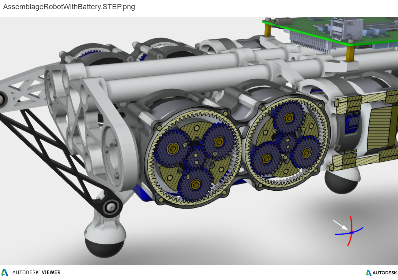
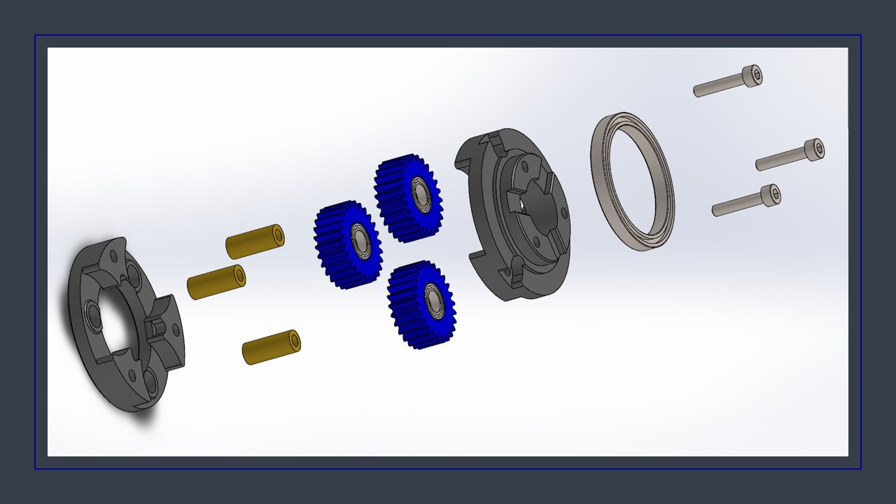
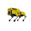
"Felin" is a small 12-DoF legged robot, using quasi-direct drive brushless actuators. Most of its parts, including epicycloidal gearboxes, are printed using a FDM 3D printer and PLA. It is intended to race at the Toulouse Robot Race in 2022.

This quadruped has four lightweight legs, based on the 5-bar mechanism. There are two femur and two tibia, per leg. Two actuators at the hip control the femur angles, and knees are just free joints.

This robot uses the B-G431B-ESC Brushless Servo Controller, which is an open source side project, bringing an "ultra low-cost controller for brushless servo based on the B-G431B-ESC1 Discovery kit by ST". A FOC algorithm is running at 40KHz with programmable PD position/velocity and PI current control.

A "Felin" ROS node, implementating a simple 3-DoF trot gait and a 6-DoF attitude control, is also developped. The robot is remotely controled by a wireless Bluetooth Gamepad (PS3-like). Gait algotrihm is still under

Build instructions in video : 


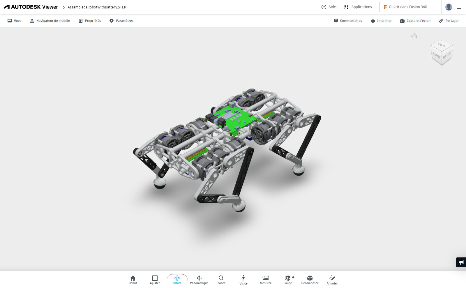
Mechanical design viewer :  https://autode.sk/3qW5eA4

ESC Firmware :

Actuators based on project: "Ultra low-cost controller for brushless servo based on the B-G431B-ESC1 Discovery kit by ST" : https://hackaday.io/project/177578-b-g431b-esc-brushless-servo-controller

Custom Firmware for ST Discovery Kit B-G431B-ESC1 may be downloaded from git : https://github.com/pat92fr/BrushlessServoController


ROS node :

Instructions v0.01.pdf

Felin mount instructions

Adobe Portable Document Format - 10.70 MB - 04/03/2022 at 13:03

Preview

STL v0.01.zip

Felin STL files

x-zip-compressed - 1.93 MB - 04/03/2022 at 12:46

Download

STEP v0.01.zip

Felin STEP assembly

x-zip-compressed - 10.48 MB - 04/03/2022 at 12:47

Download

  • 12 × MAD 5008 KV240 IPE V2 motors
  • 12 × B-G431B-ESC1 ST Discovery Kit programmable ESC
  • 12 × AS5048a (PWM) or AS5600 (I2C) board with hollow magnet position sensor (encoder)
  • 1 × SBC with CAN port(s) Single Board Computer : UP-Board Xtreme + Peak PCAN M.2 QUAD

  • Very first steps

    pat92fr04/03/2022 at 13:56 0 comments

    Patrick.

  • Foot trajectory planning

    pat92fr04/03/2022 at 13:54 0 comments

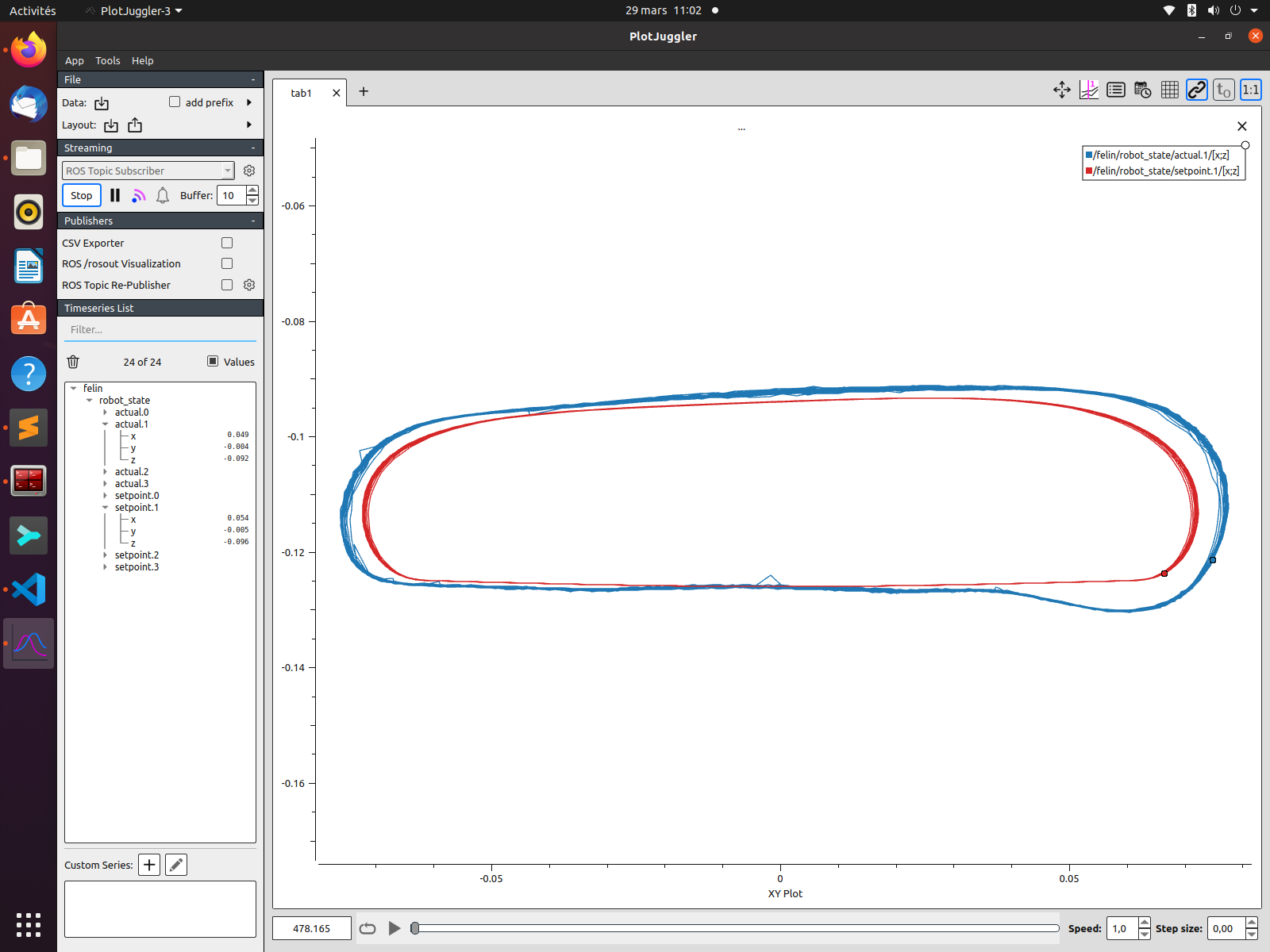
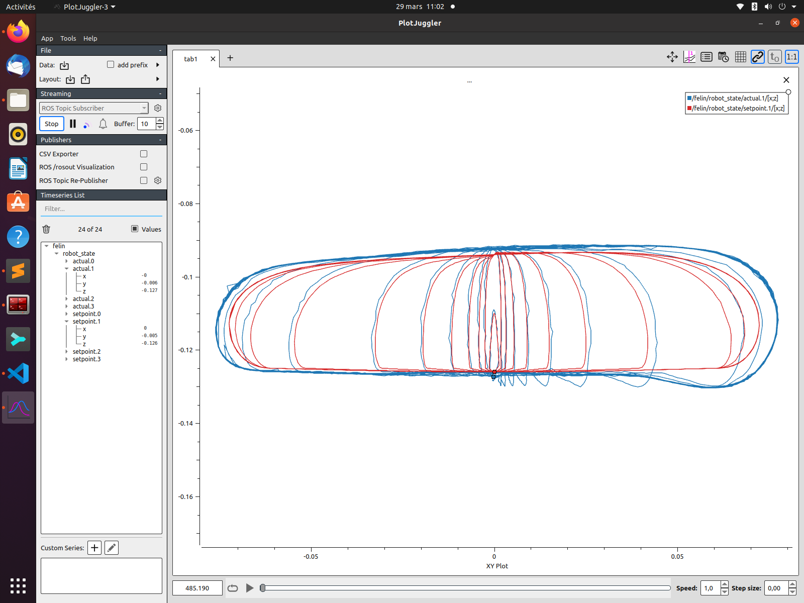
    Testing a foot trajectory at high speed using Bezier curve.

    I was looking for a smooth swing phase trajectory for my DIY legged robot, that suits a large range of robot velocity (from 0 to 1 m/s and more). This trajectory shall be computed in real time, and should minimize foot velocity and acceleration, and joint velocity and acceleration, in order to get a good tracking and minimal ground impact force at the begining of the stance phase.

    The Bezier curves solution is not yet perfect! There is still a position overshoot at the begining of the stance phase, that could cause a ground impact at the touch down. Foot position tracking at quite a high velocity is not too bad though, and depends on the foot trajectory curve and also on the brushless motor controler setup (Kp and Kd of the position control loop, Kp and Ki of the FOC current loop, FOC implementation). The PID has been set for the a robot walking on the ground, that maybe not be optimal when the robot is not in contact with the ground. Well, that require further analysis, but those first experiments are interesting.

    Git : https://github.com/pat92fr/FootTrajectoryPlanner

    Patrick.

View all 2 project logs

  • 1
    Build instructions in video
  • 2
    Build instructions in pictures

    See. Instructions v0.01.pdf in file section.

View all instructions

Enjoy this project?

Share

Discussions

jeongsukchul wrote 04/01/2024 at 01:04 point

why did you design the leg like a chain of link, not like mit cheetah.

What is the benefit for design like that.

  Are you sure? yes | no

Afreez Gan wrote 05/26/2022 at 14:29 point

Any advice about the below GIM4305 motor compared to the MAD5008 motor? Thanks!

https://www.aliexpress.com/item/1005003433829950.html?spm=a2g0o.productlist.0.0.21ad27cdOMVPLQ&algo_pvid=c43770ea-4ea3-40b9-9edc-66e7a0e05210&algo_exp_id=c43770ea-4ea3-40b9-9edc-66e7a0e05210-1&pdp_ext_f=%7B%22sku_id%22%3A%2212000025769288175%22%7D&pdp_npi=2%40dis%21USD%21%2184.9%21%21%21%21%21%400b86d81616535750300914968e76fa%2112000025769288175%21sea&gatewayAdapt=4itemAdapt

  Are you sure? yes | no

pat92fr wrote 05/28/2022 at 06:35 point

Hey, I have seen thismotor/reducer too. For a 3.5kg robot , I think these motors are suitable for such a quadruped. Test must be completed ti check the strength of reducer (impact resistant gears).

Patrick.

  Are you sure? yes | no

Afreez Gan wrote 05/28/2022 at 07:33 point

Many thanks for your info!

  Are you sure? yes | no

Afreez Gan wrote 05/26/2022 at 14:12 point

Awesome project!

Any advice if hope to reduce the weight from 5.5Kg to 3.5kg? Thanks!

  Are you sure? yes | no

pat92fr wrote 05/28/2022 at 06:29 point

Hello Afreez Gan, 

An overall weight of 3.5kg was my target during mechanical design.

Note : The weight of the 12 motors is about 1.7kg.

First, the Up Board is quite heavy, and such a powerfull SBC is not required for this robot. Replaced by a RPi+CAN HAT or a even smaller computer (M5Stack) is possible. Expected weight reduction : 400g.

Second, wiring is quite heavy due to the reuse of COTS ESC. There are a lot of cables, connectors (dupont,xt30/xt60), stand-alone magnetic encoder boards,
and even intermediate boards for power and CAN distribution. By redesigning the FOC controller, with daisy chain for both CAN and power, the expected weight reduction should be about 400g.

Third, reducers and legs are quite heavy too (800g for the 4 legs for instance). By replacing FDM parts (legs, gears, reducers, frame...) by injected/molded plastic parts, and by redesigning parts with a higher level of optimisation (more simulation of forces and deformation), I think that an noticeable weight  reduction is possible. By te way, molded plastic parts allow suppression of a few M3 to M5 screws.
By using materials like nylon and PTFE, some ball bearings may be suppressed too.

A weight of 4kg may be possible, and the performances of the robot will be greatly improved.

Patrick.

  Are you sure? yes | no

Afreez Gan wrote 05/28/2022 at 07:33 point

Love your professional and detailed advice, so great! Thanks a lot!

  Are you sure? yes | no

pat92fr wrote 04/03/2022 at 13:58 point

Comments about robot design and programming are welcome. Thank you!

  Are you sure? yes | no

Similar Projects

Does this project spark your interest?

Become a member to follow this project and never miss any updates