With my degree behind me, I'm soon going to lose the reason I attended in the first place: the manufacturing facilities. The good news is that, unlike back in 2016 - 19 when I went from 0 to 5 3D printers, there are quite a few outsource options in my league budget now that it's 2025; this fact is unlikely to stop my pursuit in 3D-printed multilayer boards seen in #SlimeSaver [gd0105]. The bad news is that I was scrolling Amazon, looking at all the nice FFF 3D printers, and then realised that none of them had a coaxialising feature:
My feel when I can't buy a printer nor outsource a part with features that a Coaxial8or makes possible.
The goals
I knew that if I was to engineer a 4th revision, it would have to achieve the following:
Merge 8 inputs into 1 in the smallest possible way for sharper (buffered) changes
Reduce the volume between the merger and nozzle tip. The coaxializer geometry is more or less fixed, so the aim would be a shorter input path and shorter nozzle.
Drastically reduce the cost of the heatblock. In other words, reduce the printed volume. Ideally, the cost will be reduced such that, like with the current nozzle trend, the heatbreak can be permanently attached to the block. Essentially a unibody hotend that works and doesn't cost £200.
Per-input toggling using the heater valve idea I mentioned last year.
Tubing
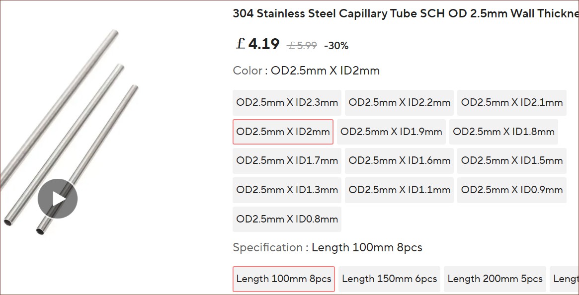
First thing I found was suitable stainless steel tubing with a 2.5mm OD and 2mm ID. If desirable, I could even use 1.9mm ID:
100mm might be a bit long but it should be serviceable.
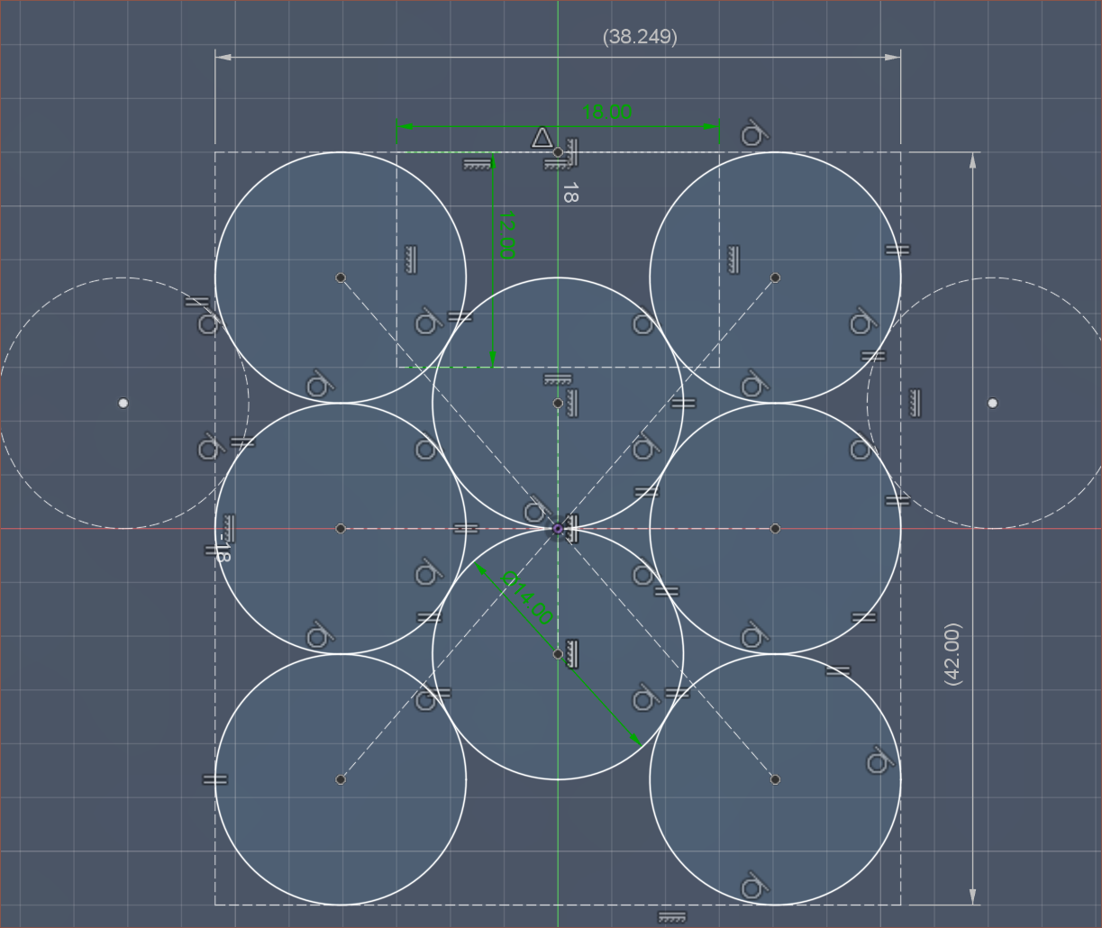
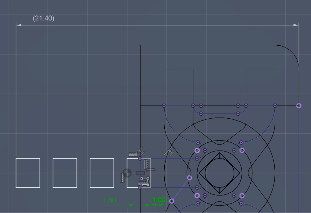
I did a bit of moving around of the inputs to take the 14mm CR-10 bolt locations into account:
Then I wanted to learn about how the tube is fitted permanently, and it just sounds like tight tolerancing, potentially using thermal expansion to their advantage during the insertion step:
CrealityE3D Revo
Well, a thermistor is still stuck in the Coaxial8or R2 heatblock so I guess a straight hole really does work?
Looking at the Creality version, I'm going to assume I need at least 6mm inserted into the heatblock.
Minimum heatblock cost
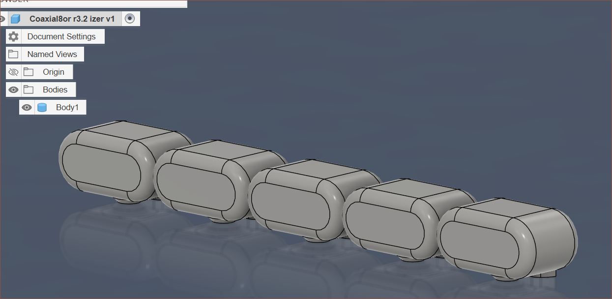
I cut out the coaxialiser from R3.2:
I tried 4 different online SLM autoquotes for aluminium (except JLC) and here's what I found:
It seems that the cheapest method is to tab multiple pieces into the same .STL file. PCBWay did 5pcs for $33 but 10pcs in a single file for $31.
PCBWay: $30 for x1, $31 for x10
Elecrow: $27 for x1 or x10, $29 for x12
Unionfab: $8 for x1, $26 for x10
JLCPCB (stainless): $8 for x1, $15 for x5, $29 for x10
10pcs is about 15.5 cm^3.
Heat control
I learned a bit about the KSD9700 and its suitability as bang-bang control of the heater. They are available up to 250C. Still, due to potential surge currents if all 8 inputs are active (though 4 at a time is much more likely), a more active control method may be required. This may also need a 12V supply since the ceramic heaters only come in 24V 50-80W options. I was planning to use the cylindrical ones, but then I realised that I'd be able to get the inputs closer together with the rectangular heating element.
The best heating element I've seen so far is the one for the Flashforge 5M (above) since the cable isn't too long (only 5cm), the thermistor is on the same connector (similar to a heated bed, for example), the heater is a not-too-extreme 50W and the whole thing typically costs less than other options for the heater alone (typically costing £18 for 10pcs).
The dimensions of the heating element are 15mm x 7mm. In a similar size, there's also mini copper heatsinks (below), so I may be able to acquire 16pcs of a part designed to facilitate heat transfer to/from the tube.
I still don't know precisely how I'm getting all of this attached, with boron nitride paste being the most likely option.
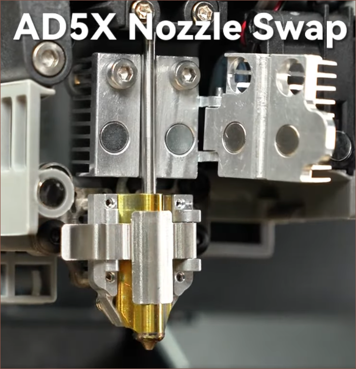
I went to research more about Flashforge hotends and I found this for the AD5X:
This is very insightful since it implies that a heatsink can press against a plain steel tube. I mean it makes sense, since this is how clamp-based heater cartridges work, but this is the first time I've seen it done for the heatsink. Since there are magnets, it also implies that the operating temperature of the heatsink is unlikely to exceed 80C.
Something else Flashforge does is include a useful unclog pin in the box. Hopefully this would be better than trying to use an allen key:
Nozzle
I wanted a nozzle that was at least stainless steel, and ideally something in the ballpark of hardened steel. This is so that the orifice maintains a high quality during use, without having to worry too much about general wear. The modern-day nozzles use a hardened steel tip.
My first idea was one large nozzle, such as an M10 nozzle. However, the inside of the nozzle is flat so there's still a good 6mm to the tip. Additionally, the coaxializer is just too large to fit anyway.
As I was searching through nozzles for welders, sprayers and hot glue guns, I found this Bambulab A1 nozzle that was only 8mm tall and seemed to have an M4 thread:
It comes in brass, stainless and ✨hardened steel✨. The issue is that, as I've experienced, I wouldn't be able to complete the threads without at least 7mm of space, which is one reason my Coaxial8or R2 and R3 used volcano nozzles. But very soon after, AliExpress showed me T-slot slide-in nuts:I connected the dots.
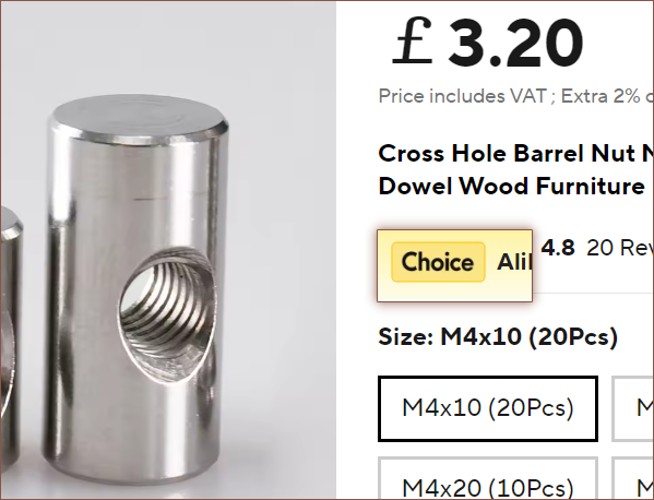
The issue is that these nuts are zinc-plated carbon steel (thus only suitable up to 105C), except the 3030 variant which is nickel plated. Many rectangular nuts were also zinc-plated. Ooznest had stainless steel T-slot nuts for £2 each. But then I discovered stainless steel dowel pins with a thread, typically called "barrel nut" or "cross dowel":
The nickel plated T-nut was a rather large 16 x 16 x 6mm, but these dowels were 6mm OD and as short as 10mm. Additionally, using this as the insert would allow for 1 axis of rotation, further reducing tolerance requirements between the nozzle and heatblock face. Thus, I did some tweaks and modifications to see how suitable it was:
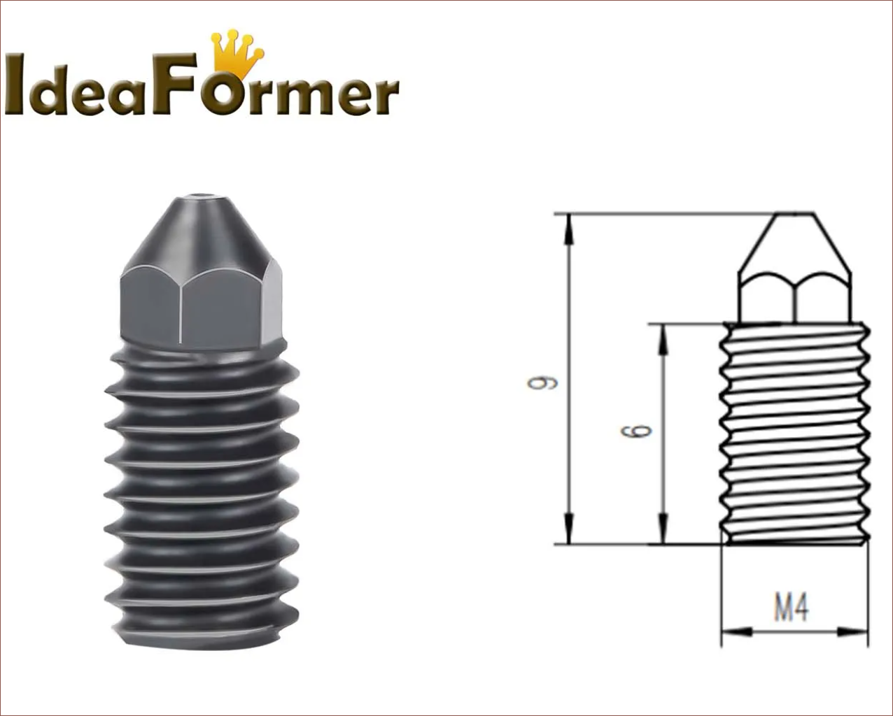
As you can see, the 3mm hexagon is almost entirely blocked by the dowel. I did some looking around and found that TriangleLab, IdeaFormer and JUUPINE makes a hardened steel version that's 9mm tall due to a 6mm thread:
At £1.46 excl VAT, It's only 40p more than the 8mm version I found.I found this about an hour after I wrote this log. They're offering a second nozzle for merely 8p more than IdeaFormer.
These nozzles look to have the same proportions as the Phaetus Conch EndCoat nozzle, which claims to have additional abrasive resistance.
£3.92 excl VAT, as a point of comparison.
I haven't felt the need for fiber-filled filaments at the moment, so the standard hardened-steel should be fine for my needs. It's just nice to have the option down-the-line.
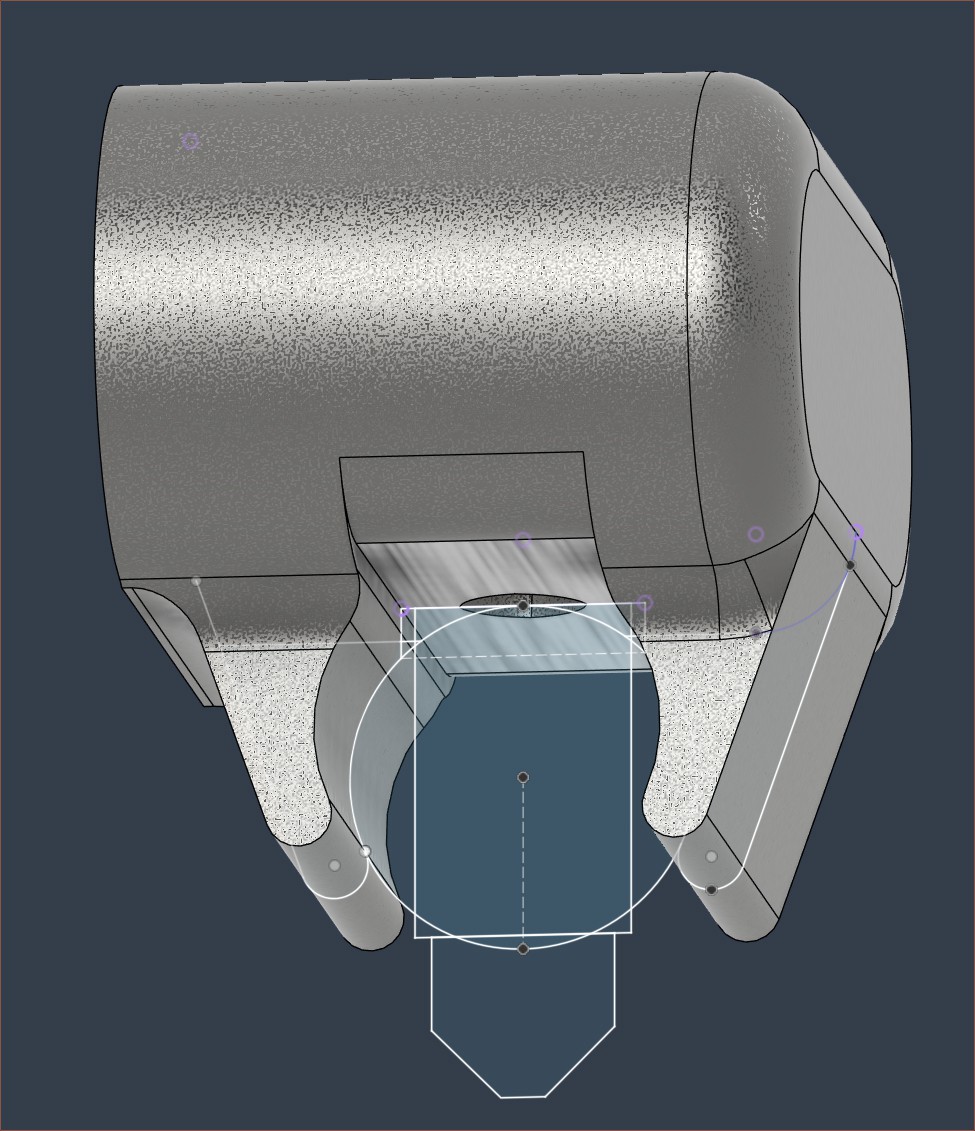
Below is the design I've got, which has the filed-down face seen in Coaxial8or R2. This also allows me to screw the nozzle into the dowel and use it to align the dowel as it's slid into place. This reduces the coaxialiser output to nozzle output distance from 23.5mm to 10.2mm.
Inputs
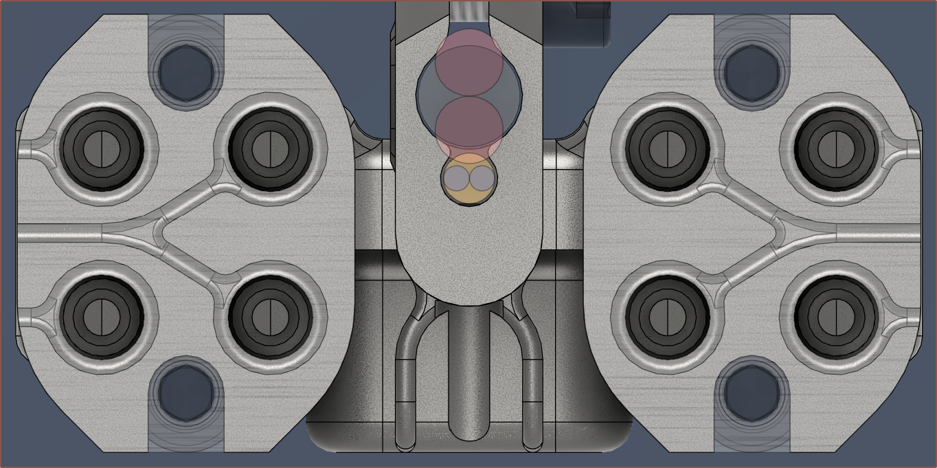
My strategy for merging the inputs is to feed 4 from the top and 4 from the bottom of a short path towards the coaxialiser. I might also be able to make the actual input channels slightly thinner than 2.2mm without causing blockages to further minimise the merger:
I would only be able to route the compressed input version if they alternate, such as North, South, North, South in the above. I couldn't have all 4 (top/bottom) inputs coming in from the North, for example.
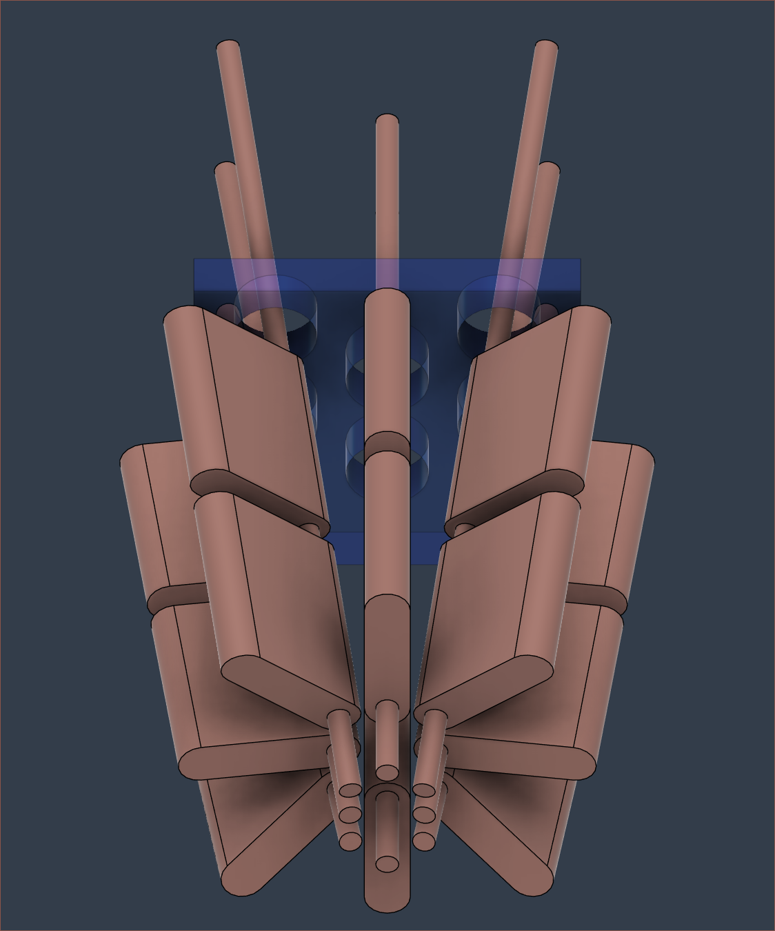
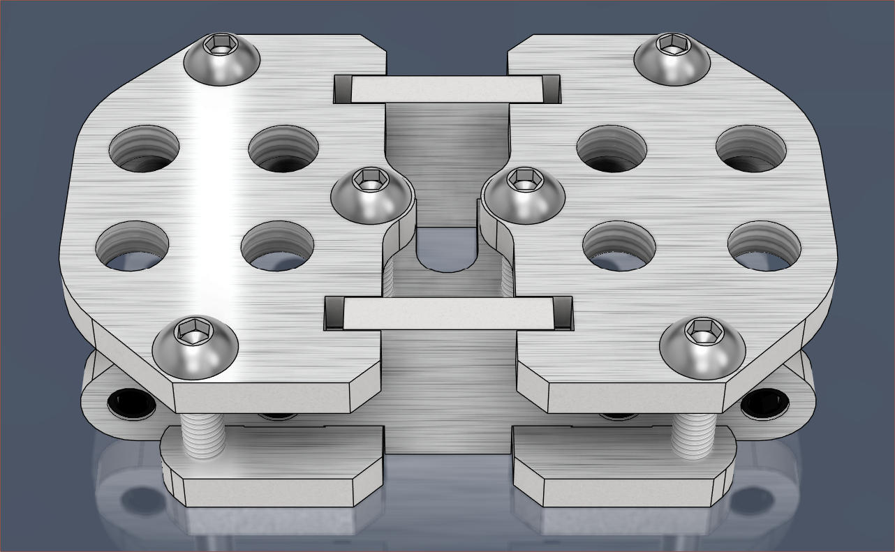
For the heatbreaks, I did some designing and rotations and obtained:
Each heatbreak is a stainless steel tube with the bottom block being a heater and the top being the heatsink. Due to the heatsink being 22mm, the blocks are the same height.
I'm not sure how suitable the heatsink orientation would be since the blower air needs to actually reach them, and they're quite small too so the amount of energy they can dissipate also comes into question.
The angles are much less extreme than I thought (I was expecting something more like the Diamond Nozzle) and the resulting inputs can be brought very close together. I was initially imagining that I'd have to figure out how to bend the tubes to get this kind of shrinkage. However, the middle inputs may need to move or else they may stab into the merger.
Conclusion
Considering that I've been somewhat stuck on this project for months, I'm somewhat surprised how many insights I could find over the past 2-3 days.
Due to the relatively narrow heatblock and even thinner heatbreaks, the codename for this attempt is ThinFET, derived from the "FinFET" name. Maybe FET could stand for Fold Effect Transition because the coaxialiser takes a material sandwich extrusion and folds it into a coaxial?
I had an idea and it turns out there is an off-the-shelf part that exists:
Coincidentally, it seems that M6 is the only option that even has a flange substantial enough to work.
Instead of having to carefully tap stainless steel threads for 90 minutes and still have them slightly misaligned, the idea is to have appropriately sized holes in a steel plate and the insert flange sandwiched between the plate and the heatblock. The insert is somewhat tall but I feel that it will be quick work to file them down.
As you may see from the image, the minimum spacing between inputs will grow to 14mm, but it's probably for the best. There's a bit more heatsink / bowden coupler options available when the spacing is above 12mm. For context, the Coaxial8or currently has 10mm spacing.
One of the goals for the next design will be to have the 8 inputs converge as near as possible, hopefully so that changes are faster. Thus, the input pattern may follow the Kobra 3 Filament Hub:
The aspect ratio is somewhat squarish though, which might not be ideal:
I'm thinking that this could allow for direct-drive extrusion for 3+ input hotends without the drawbacks of other methods such as a semi-stiff stick or mounting many heavy motors on the end effector.
If I understand correctly, I think this would even be Core XZ compatible, allowing all steppers to be in the base of machine like the Ender-3 V3.
So after spending some days wondering what to print (and finding out Orca will throw out all my settings if I open a .3MF with some,) I decided that I was going to tune scarf seams and M592.
Seams
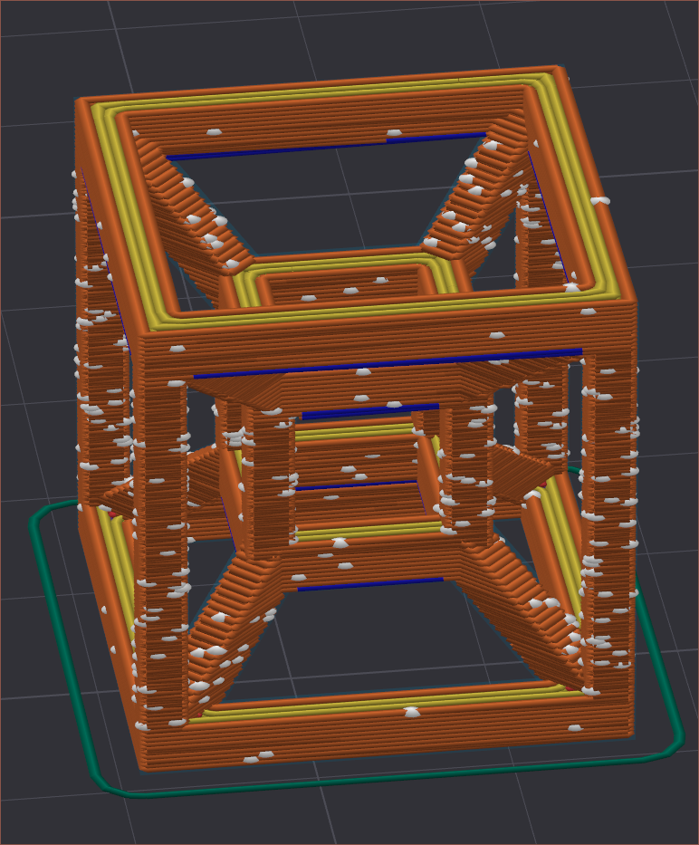
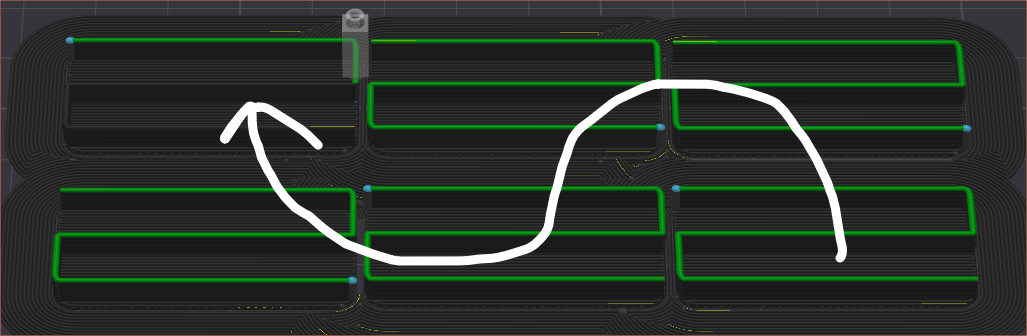
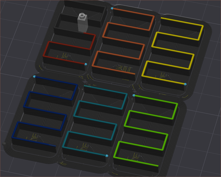
I started off by learning the research posted in this guide on Printables and its comment section and applying it to a tesseract 3D model because "what point is a test print if you have confidence it'll print fine?".
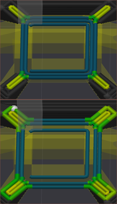
I changed the z-seam location from random to aligned because some layers would try and start on an overhang.
I tested things like Inner/Outer vs Inner/Outer/Inner and, even with the latter looking questionable in the 90-degree overhang section (see below), I watched the print and came to the same conclusion that it's better.
I also set the bridge acceleration to 150mm/s2 which greatly improved the bridge actually anchoring to already-printed sections. I'll need to test more on a dedicated .STL in the future, but looking at the string left at the end of every print (as the hotend moves to the upper left corner over 20cm away), I think the strategy is low extrusion multiplier and low acceleration.
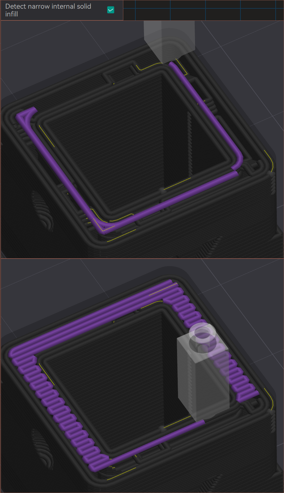
I tried a ripple cube STL I downloaded probably a dozen of years ago to see my current results on an easier print, and I had to turn off "Detect narrow internal solid infill" because it would try and bridge in midair:
I enabled Mesh Bed Levelling to help mitigate the first layer issues I had been having. I should've tried MBL out way earlier. A fade height of 3mm looked to be fine, considering my bed is only warped by 0.4mm.
I then moved onto this model to better see what the seams were doing:
I tested:
Wipe retract percent of 100% and 0%
I was going to try 50%, but 0% was miles better than 100% that I didn't even bother. I believe it's because the printer has to momentarily pause to do the retraction, causing a secondary "seam" (shown in white in the image above)
Scarf start height of 12.5%, 0% and 25%
I've got staggered seams enabled, and 25% looked the neatest.
Seam gap 6%, 50%, 0%
50% just spaced out the seams.
0% was slightly more compact than 6%
Wipe before external loop
I didn't have it enabled and the seam stuck out a lot less when it was.
Wipe length 3, 6, 1.5mm
6 slightly better than 3 which was notably better than 1.5.
I remained on 3mm.
M592
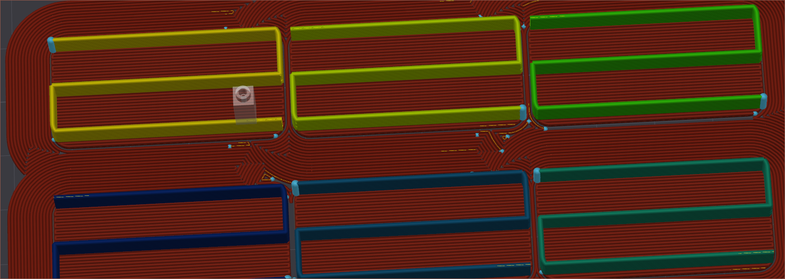
As I was printing, I noticed that my infill line wasn't starting all that well, and thought of an idea to test M592 Nonlinear Extrusion.
No walls, no top, aligned rectilinear infill, 0.9mm line widths
The yellow line is fullspeed, which should be 15mm3/s. This seemed to correspond to around 72mm/s, so I went up in units of 12mm/s for the other 5. For some reason, the slicer decided to print in the following order:
The fastest one was the only one that didn't quite start the extrusion right, but all of them had varying line widths from the start (blue dot) to the end of the line.
12mm/s would start at 1.2mm and end at around .9
60mm/s would start at 0.6mm and end at around .7
A bunch of trail and testing later and the results were inconclusive. I decided to rotate the pieces to give more time for the extrusion to equalise:
Orca decided to go from slowest to fastest in this one.
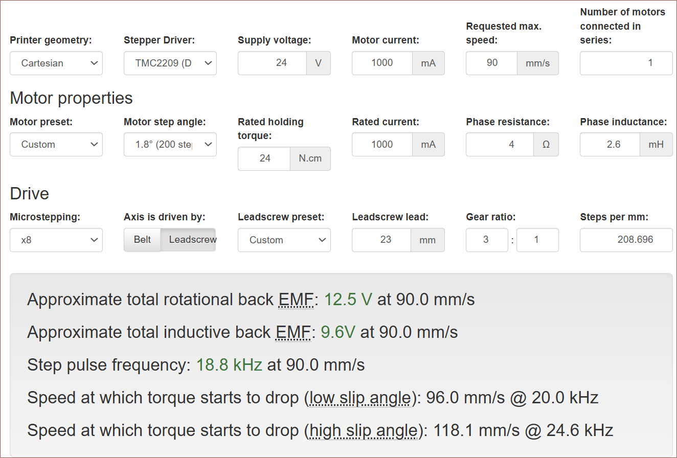
I just knew that I needed to do something about improving linear advance. One idea was a lower max e-speed in exchange for higher e-acceleration. When going into the tests, I had 120mm/s and 600mm/s2. I guesstimate to try 90mm/s, which was confirmed by using a calculator I found:
I couldn't find the exact 42BYGH24 motor inductance, so I used a similar one.
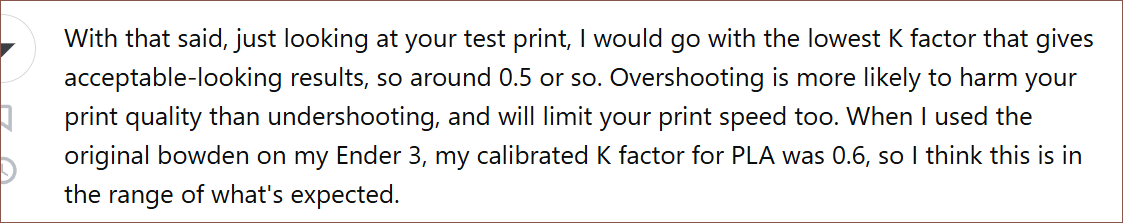
Dropping to 90mm/s, I used 0.9 k-factor to induce many E-movements and found that 3000mm/s2 worked but 3600mm/s2 had a slew of skipped steps. I then tried 0.45 and 0.6 and the latter was the best. This seems to agree with the setting found by an Ender 3 owner:
I was holding the filament during the print (to gather data on how the k-factor affected the movement) and the haptics of the 24mm/s line was quite nice. I hope to implement the feeling into #Tetrinsic [gd0041] in the future. I was also able to feel retractions, and I think 90/30 mm/s for 3mm retract/deretract respectively are good settings.
I've been tuning M592 and the amount of leaking is dramatically reduced. With more experience on how the leak propagates, I now feel that it's possible to minimise the shielding of the grub screw and make it look more streamlined. Fusion complained about my fillets so this simple change took multitudes longer than it should've.
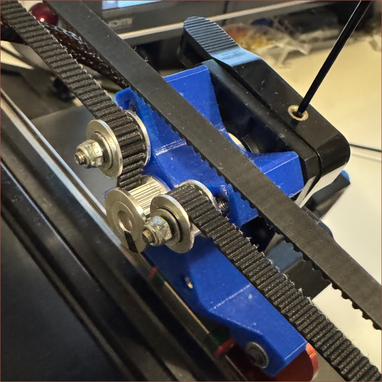
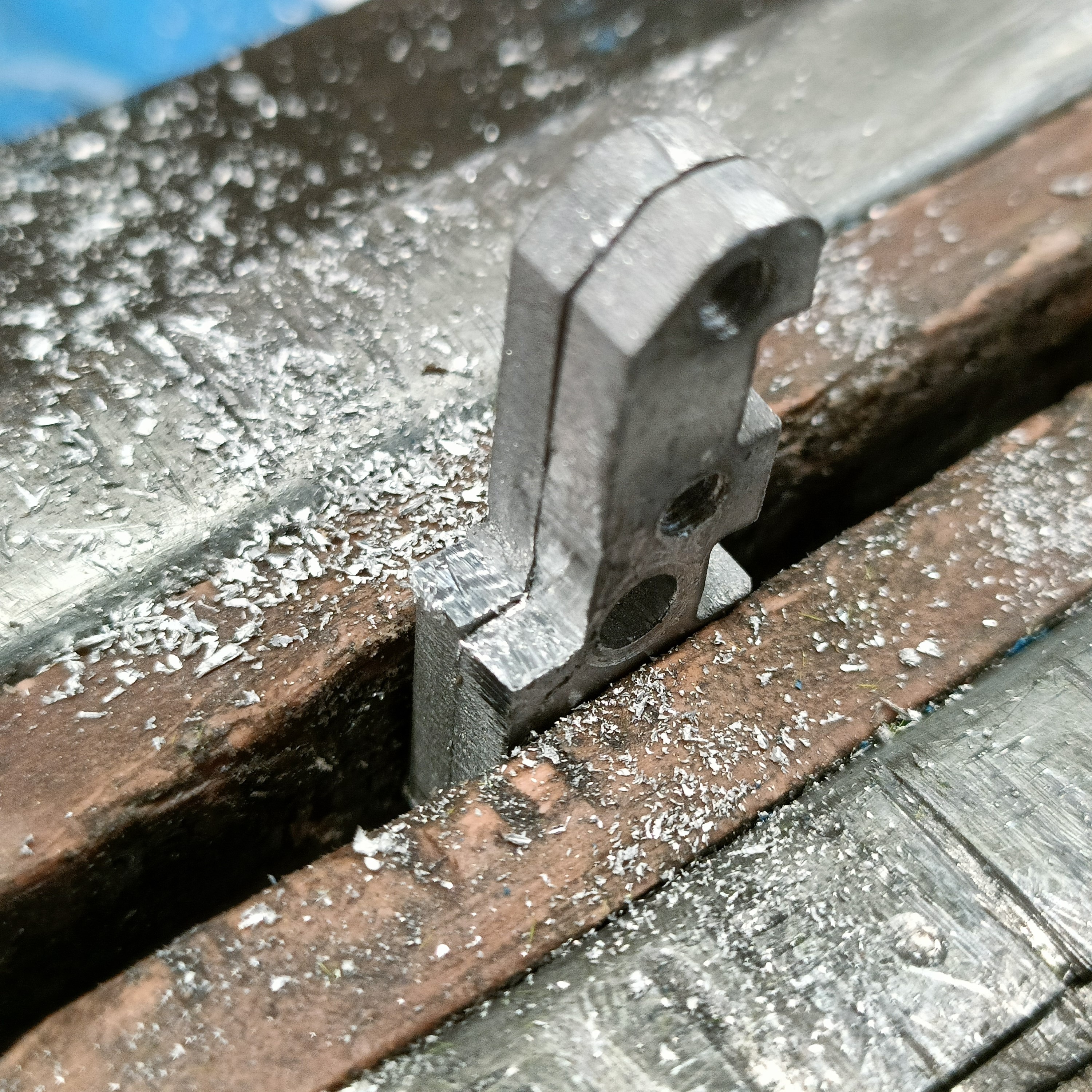
It took much longer than expected, but the new clamp and coupler plates are installed.
Removing the old plates
I guess the reason why it took longer was because of all the oozed material, which was notably less in previous revisions. It meant that the filaments didn't pop out of the heatbreaks like I've been able to do in the past. Additionally, the threads were tight in so I had to dip in hot water and then use a large wrench to hold them. I used bolts to prop them up from the table so that I could get the smaller wrench on the heatbreaks:
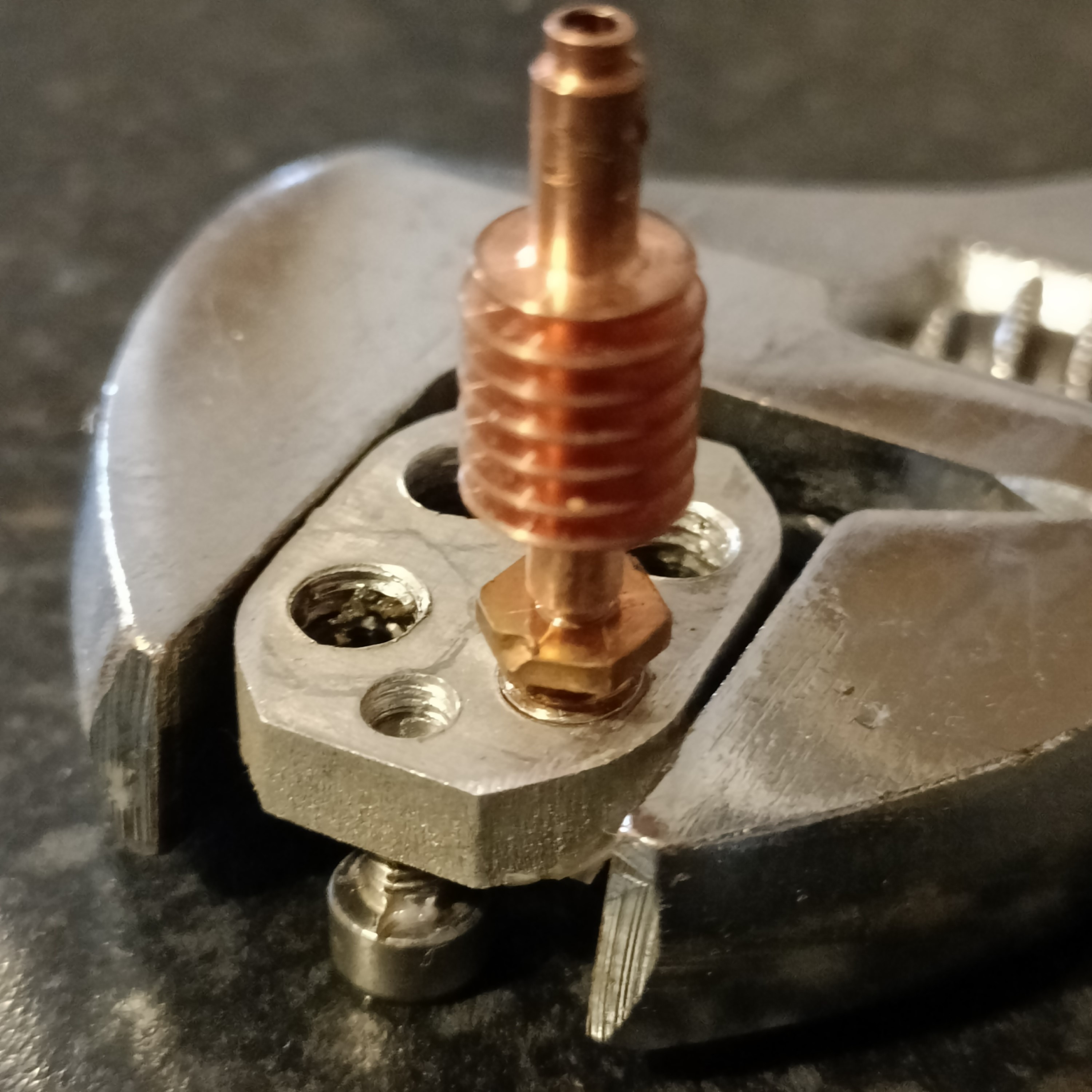
As you can see, that dent in the hexagon shows just how rigidly fixed the threads were before heating them up.
This is also the first time I've had to install them without unblocking them all, since I wasn't able to get the filament out and the best way really was just clamping them back to the c8or heatblock. The job was made harder because I only have 1pcs needle nose pliers, but because of the gaps in the design, I was able to use it to hold the heatblock while I installed and tightened the heatbreaks in the new stainless steel plates while at 140C.
I first tried 160C but that caused the material still inside the block to expand. Thus, I took the plate off and had to remove material from one channel that had stuck to the underside of the not-yet-tightened heatbreak.
Tightening the heatbrakes to these new stainless clamps feel much stiffer and confidence-inducing.
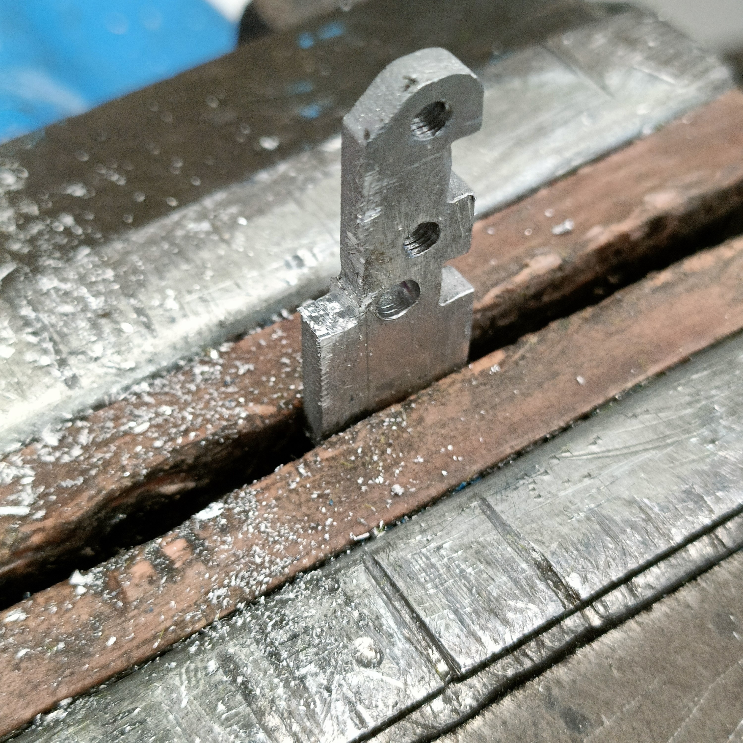
The coupler plates didn't work due to the FrontBack tabs
I spent about an hour trying various ways of installing the hotend into the holder before realising that the reason I couldn't was because of the top tabs that don't need to extend all the way. Thus I measured and tried to take about 1 - 2mm off one and then using it as a template for the other:
I then put the hotend together and it was much easier (except that I should've probably put the grub screws in before assembly).
As you can see below, I've added offsets to the CAD as well as changed the grubs to M4 mainly so that I can use a larger hex tool:
So far I haven't felt the need to screw in the middle 2 bolts, but I'll leave them in as it's better to include something I might never need than exclude something I might need.
Trivia
It takes ages (maybe 2 - 3x longer) for the Coaxial8or to cool down when the heatsinks aren't attached, suggesting that they are dissipating the bulk of the heat power and that a heatblock sock wouldn't help much.
I got 100% initial-filament-load-in success rate for the first time, meaning that the strategies I've been learning during this project are working to streamline the user experience. I think access to E6 is the only main pain point (other than the leaks).
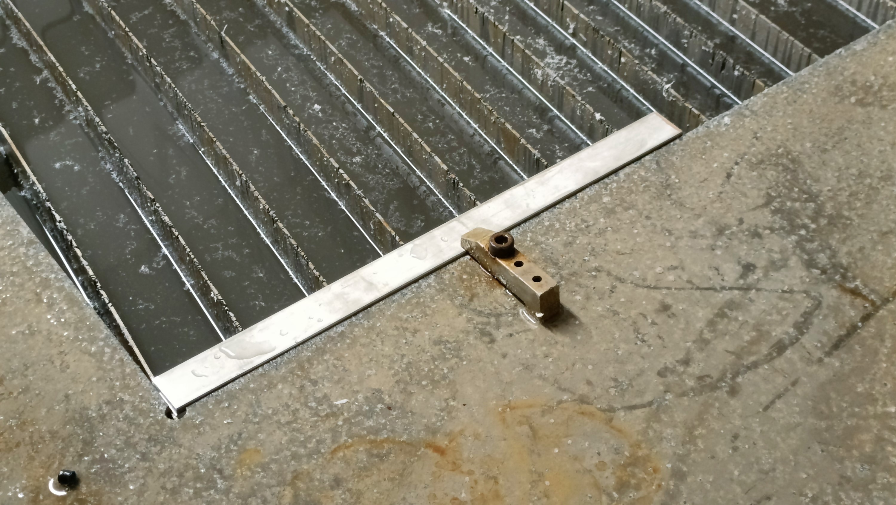
I bought a £5 bar of 330x25x5mm SS304 and got it watercut along with the new hotend holder design:
The edges of the stainless parts have an almost perfectly matte satin finish and looks quite nice.
I got 2 spares miniclamp plates cut. As you can see, the tabs were placed in the middle of the parts and have been filed off.
Tapping was tough, but that was mainly me learning the best ways to coat the tap in cutting grease, the importance to align the tap and strongly tighten the clamp and how to apply torque to the tap holder.
It felt like:
Starting the tapped hole was very easy.
Ramp up of torque required until it reached "MaxT".
(coined from MaxQ I hear in SpaceX launches)
I just had to grow the confidence that the tap wasn't going to snap, especially when the material itself makes "something snapped"-sounding squeaks every so often.
Lastly, the torque falls off, leaving me with a very smooth-feeling thread.
The offset in the CAD was -0.075mm and I've now doubled it to -0.15mm in an attempt to reduce the torque requirements.
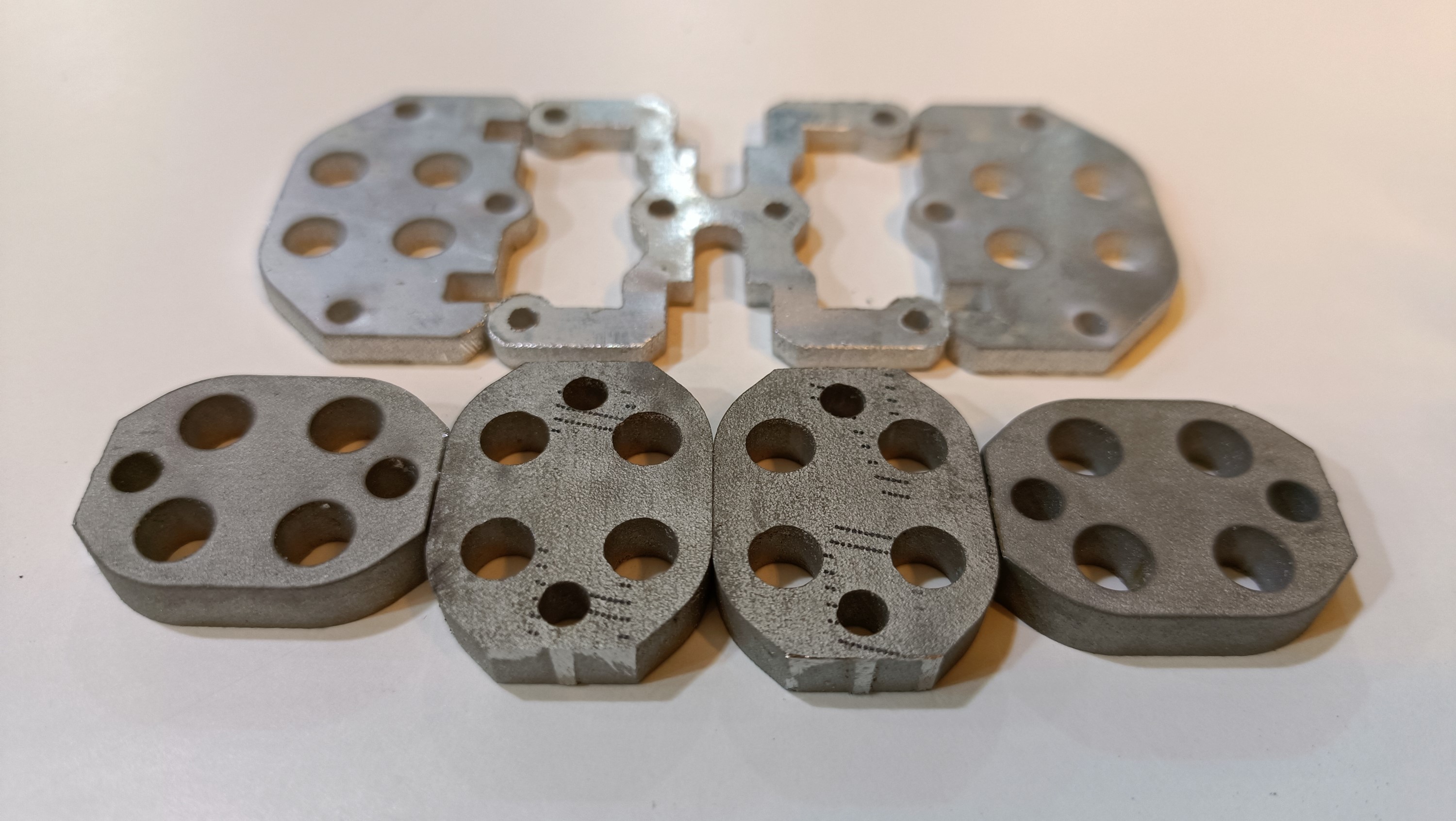
Speaking of hole offsets, when I was tapping the hotend holder top plate, the M3 holes seemed kinda small. Turned out I accidentally applied threads to them in Fusion, but a technician just happened to have a 3.2mm drill bit and a drill press:
Drill press after the 6 M3 holes were enlarged.The finished plates moments before I cleaned out the grease from the mini clamps.
R3.1 is essentially R3 with all the post-print alterations, but since I haven't reprinted, it's not the 4th revision.
To get things ready to go IPO, I just did a few small tweaks today, such as
finding a better texture
filleting the grub shield walls
changing the leak paths to
decrease the chance of leaks near the heater cartridge
increase the chance that material can be pulled out of the channels when the hotend is heated to around 100C (for PETG)
increase the speed at which a leak could be detected
I also tried my hand at the "configuration" feature that Fusion has had for a few months now:
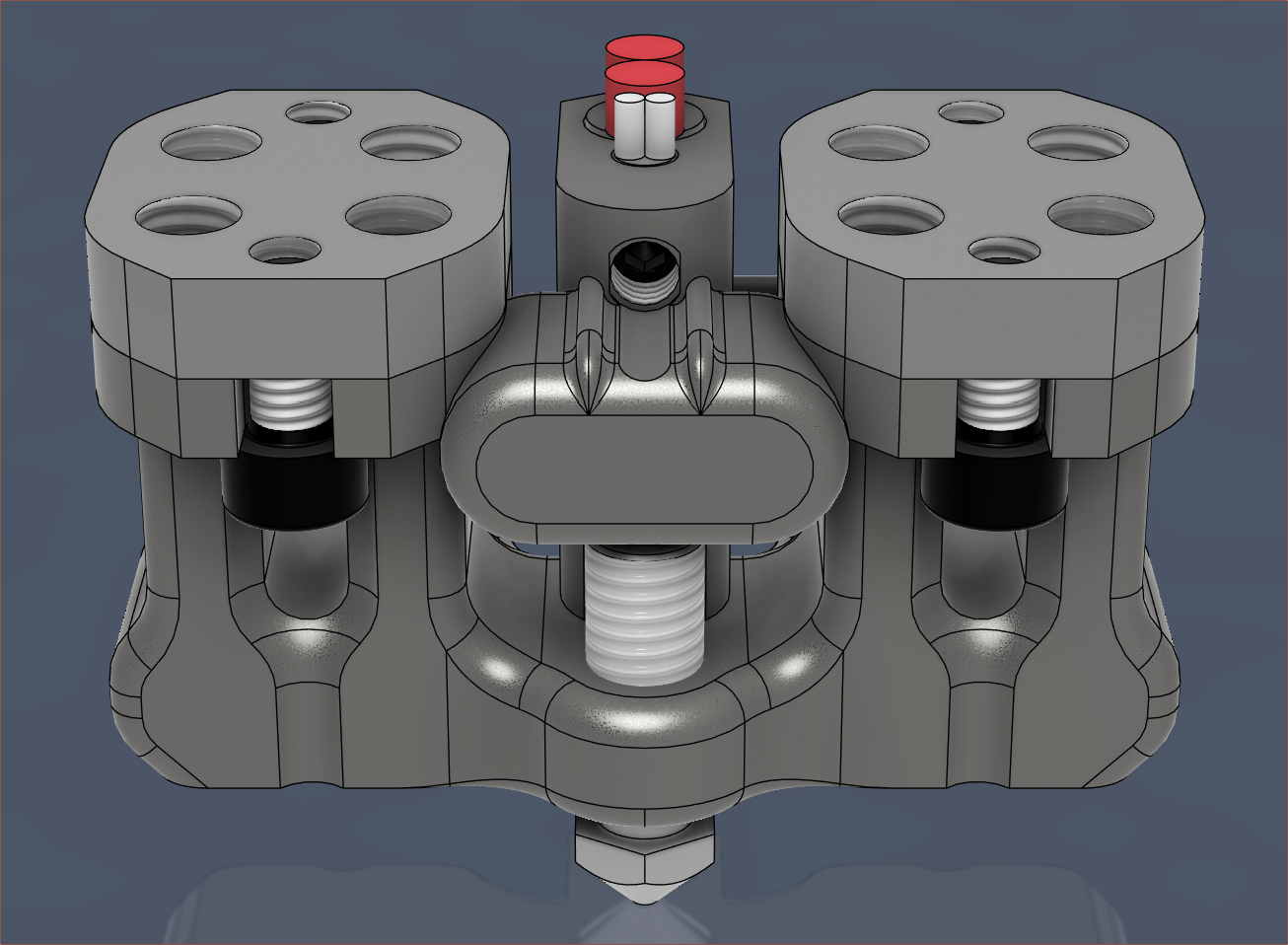
Some of the limitations I found was that you can't edit in place, nor do things like change checkboxes (Eg. "Keep Tools" in a combine feature). But now, I can quickly toggle visibility of certain components:I've also exported the .step of the hotend holder, partially because the odds that I need to continue revising it are not insignificant. Additionally, it's tangled in the rest of the "Coaxial Hotend" file and trying to "Save a copy" gave me an exploded file:I've also rendered the latest heatblock and holder:It kinda reminds me of AI-generated images by how you can see the start but not the end of the cartridge wires.
I read the Open-Source Hardware FAQ and confirmed my choice to use the CERN hardware license. I'm not sure if it matters much compared to Creative Commons in the grand scheme of things.
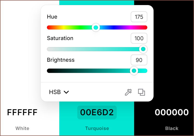
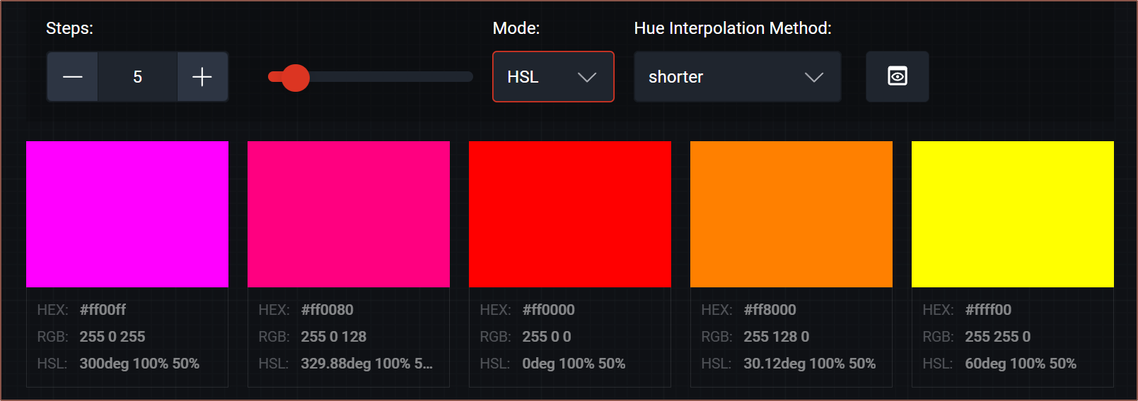
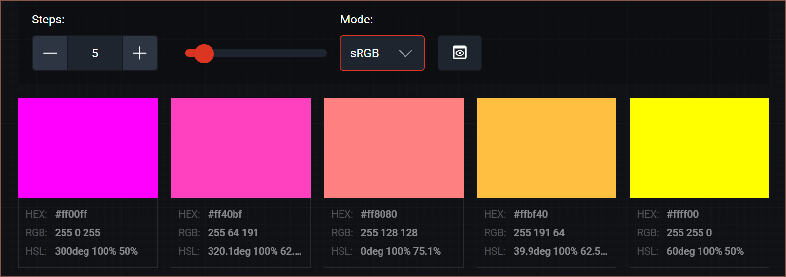
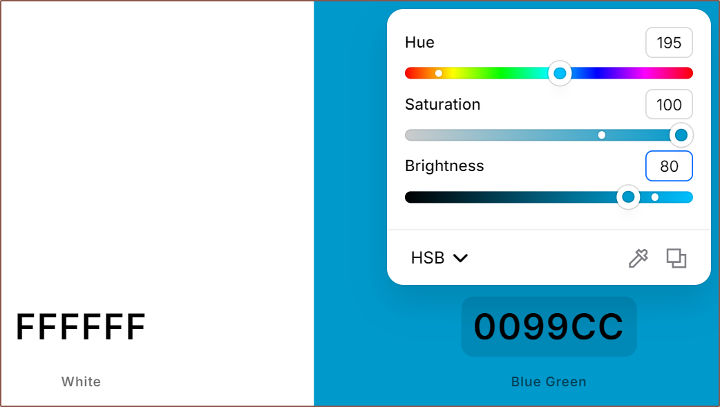
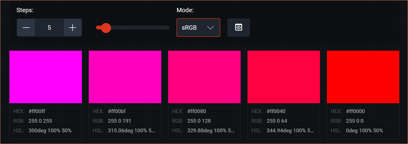
I'm currently getting great results with the compressed HSVA colour system workflow using coolors.co:
The above is the Mint PETG I have, and my workflow is to:
Use smartphone flash as a white light source to shine through the filament
My reference is:
50% - Max transparency whilst still retaining 100% saturation
100% - Effectively opaque for 1.75mm filament
Get an offcut of filament (or 3d print)
Place it next to a white reference
I'm using my white spacebar
Max out saturation and brightness sliders
Shine flash on filament sample
Move hue to nearest 5 degrees
Move brightness to nearest 10 percent
Move saturation to nearest 10 percent
I find this to be the least confidence-imbuing slider since colours look more similar, particularly at medium-low brightness values
With this, I can get a confident compressed-HSVA mentioned in this log, but I still move the sliders around by 1 step to make sure I've got the right colour:
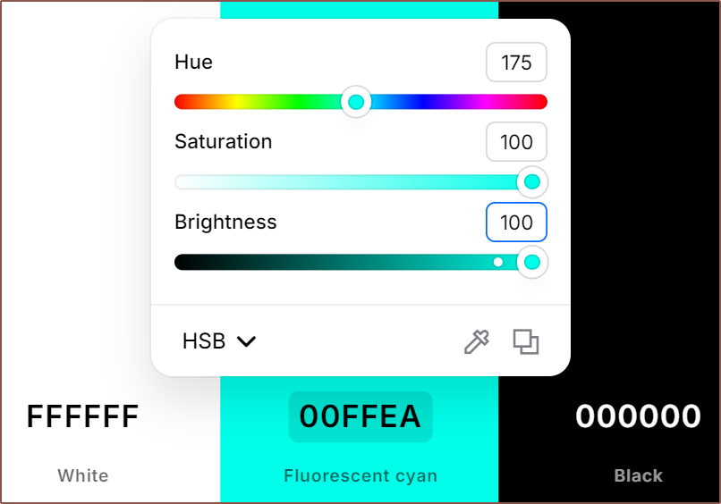
Confident YES:
Confident NO:
Confident NO:
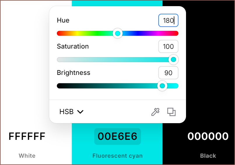
There was no shine-through for the mint, thus the colour for this not-quite-cyan is 35.a9a.
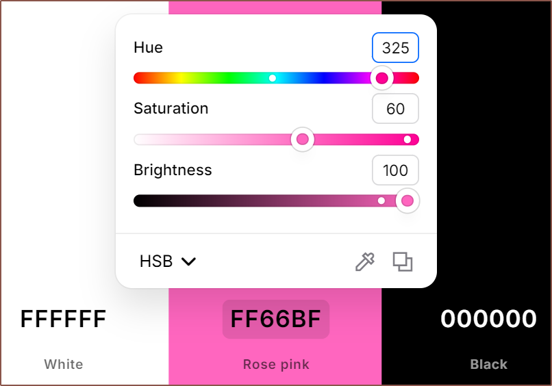
Surprisingly, my pink is so much further away from the ideal magenta. The hue of the mint is only out by 5 degrees, yet the pink is out 25 degrees and admittedly desaturated:
It also has a bit of a glow when the filament is lit from behind, so its value could be 70.6a9.
One possibility for the hue is screen colour reproduction, and I know that pinks have always been questionable on various IPS panels. On my OLED phone, this same colours looks much more vibrant... oversaturated even. On my 9th gen iPad I happen to have, the hue is 315 and other values are unchanged. This is part of the reason for the compressed colour space; there are so many variables that the precise value isn't that meaningful.
Considering a substantial amount of people have an unmodified iPad, touted with "TrueTone" technology, I will use it as the hue reference.
At least I know I certainly found colour-accurate magenta and yellow filament.
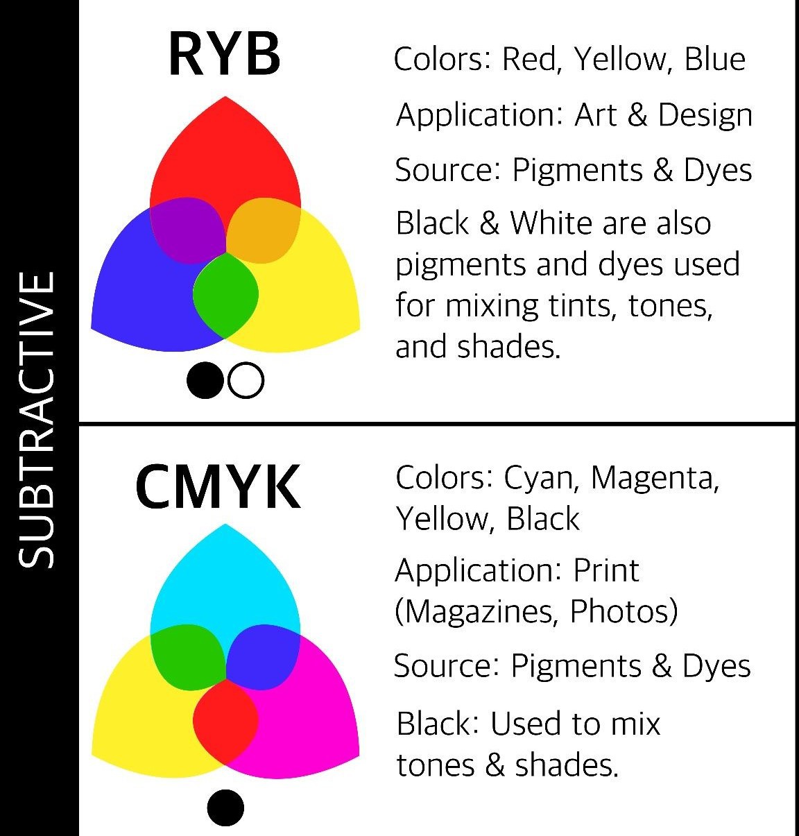
CMY and RYB
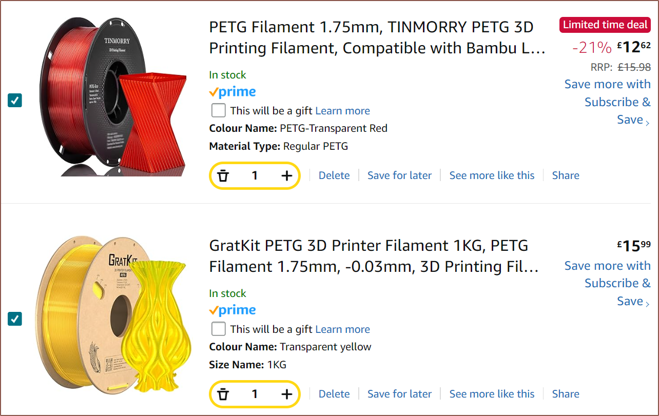
This explains why Heinz and others before him used transparent materials for colour mixing. The issue is that such filament is even harder to source, particularly for magenta. I've already got YouSu Transparent Blue, which is transparent cyan(ish): Since it's transparent, I could just hold the filament infront of the white and eye^2-dropper with the compressed colour space mentioned in the previous log.Yellow seems available, but I've only been able to find Transparent Red:
This highlights one of the reasons for the Coaxial8or project in the first place. It's one issue if you have to wait days or pay for an entire kilogram of material for a colour, and it's another issue if that colour isn't even commercially available.
Looking at the below, it sounds like one would still be able to get a decent gamut:
Another thought: maybe that's all that is needed? Maybe magenta, the innermost of the 3 hues, can stay opaque while cyan and yellow can tint it. Opacity wouldn't be very stable, however.
The alternative is dismissing transparency entirely and using 3-bit colour: White, Black, Red, Yellow, Green, Cyan, Blue, Magenta. For FFF 3d printers, transparent filaments are more like a visual effect, similar to matte, marble, silk, sparkle and glow.
 kelvinA


 It comes in brass, stainless and ✨hardened steel✨. The issue is that, as I've experienced, I wouldn't be able to complete the threads without at least 7mm of space, which is one reason my Coaxial8or R2 and R3 used volcano nozzles. But very soon after, AliExpress showed me T-slot slide-in nuts:


 Each heatbreak is a stainless steel tube with the bottom block being a heater and the top being the heatsink. Due to the heatsink being 22mm, the blocks are the same height.
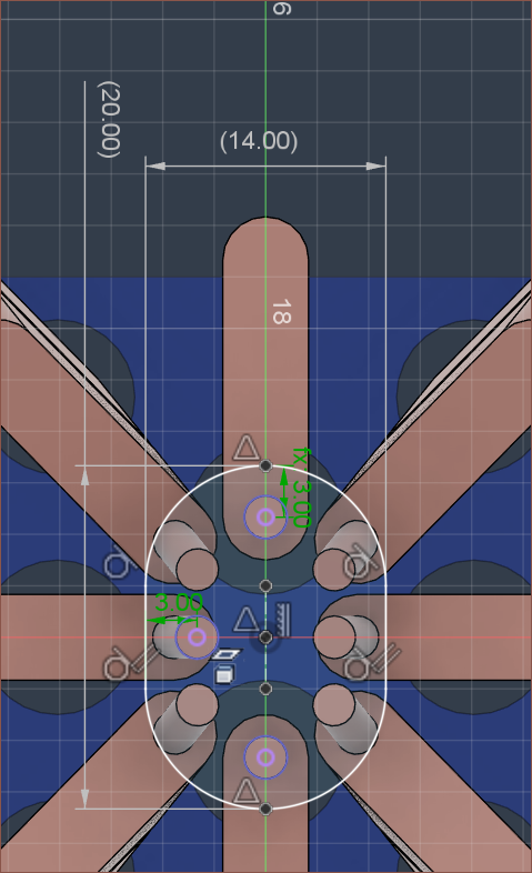

 Coincidentally, it seems that M6 is the only option that even has a flange substantial enough to work.
 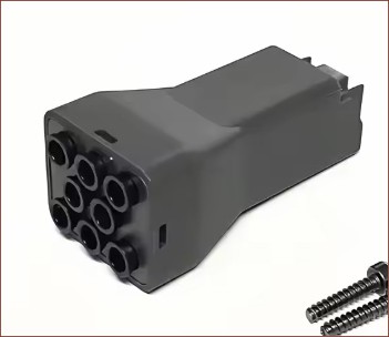 The aspect ratio is somewhat squarish though, which might not be ideal:
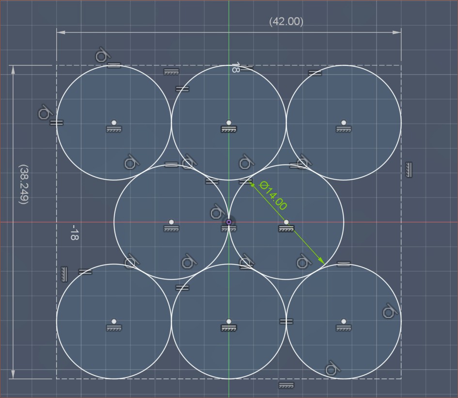
 I've been tuning M592 and the amount of leaking is dramatically reduced. With more experience on how the leak propagates, I now feel that it's possible to minimise the shielding of the grub screw and make it look more streamlined. Fusion complained about my fillets so this simple change took multitudes longer than it should've.
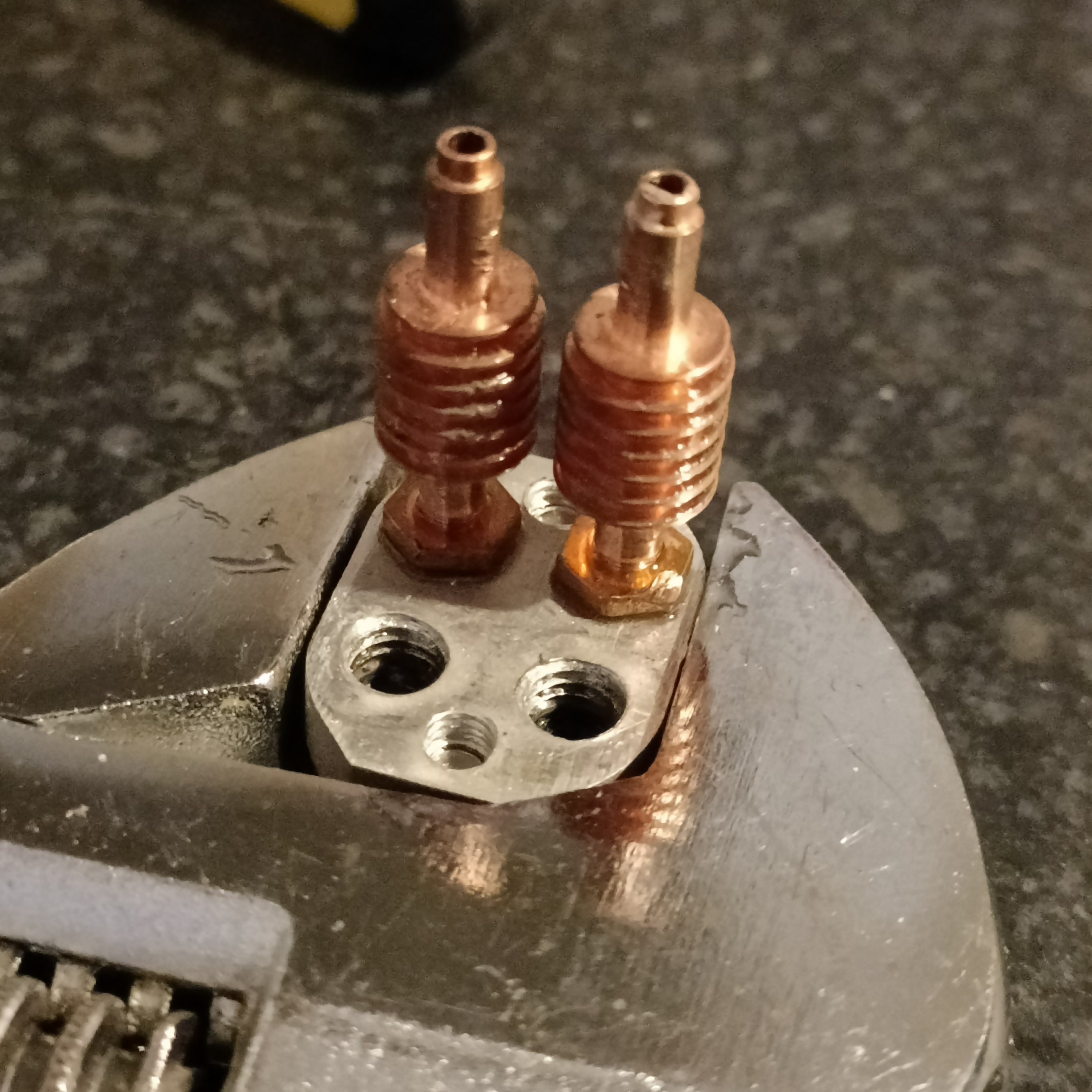

 Some of the limitations I found was that you can't edit in place, nor do things like change checkboxes (Eg. "Keep Tools" in a combine feature). But now, I can quickly toggle visibility of certain components:
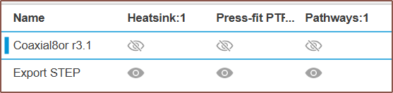 I've also exported the .step of the hotend holder, partially because the odds that I need to continue revising it are not insignificant. Additionally, it's tangled in the rest of the "Coaxial Hotend" file and trying to "Save a copy" gave me an exploded file:
 I've also rendered the latest heatblock and holder:
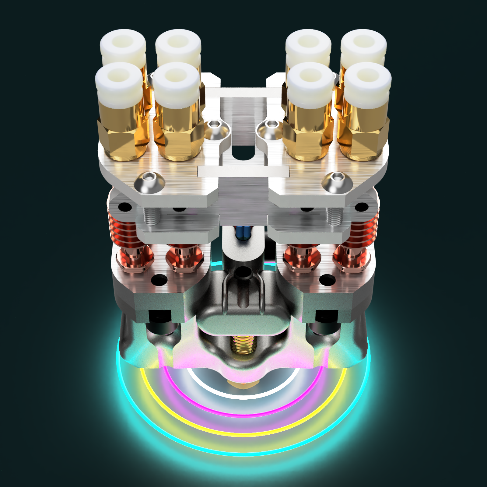
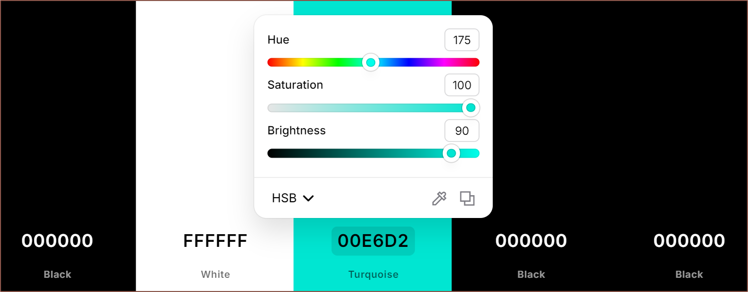 The above is the Mint PETG I have, and my workflow is to: