-
[C] Marlin M165 improvements
02/25/2024 at 15:11 • 0 commentsI have just finished creating a PR for MarlinFirmware for improvements that I needed so that I could realistically test this project whilst not having "Marlin Mode" on the TFT. This PR is my second one ever. I tried to avoid it, but I needed to merge the first PR into the second so that all 8 extruders were supported.
Disconnected fork
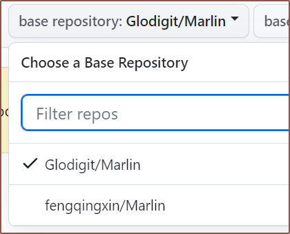
The first thing I did was the fix to allow 8 mixing extruders. That was simple and straightforward because I had already done it and just made a new branch in Github and manually copy-pasted the change. Then I went to try and submit the PR:
It turns out that my Marlin fork didn't actually show up as a fork of the main repo, and research suggested that there was no feature to "retroactively fork". I had to make a new fork and then do things like
git remote add lc-old [url]     -- Backup repo
git rebase common
git push lc [branches I wanted]
and a few other things
Multiple potential solutions
Here's a list of the inital things I could learn from reading the codebase:
- V-Tools are not preserved / saved in EEPROM and are reset on boot
- Marlin makes use of a copious amount of macros, making the code more readable.
In my university studies, I've always kind of wondered why having more than 1 solution is a problem. Well I found out first hand when I was coming up with a solution to how to go about getting mixing extruder support on the touchscreen.
- I found out rather quick that there's currently no way for the TFT to even get the information it needs because nothing in marlin reports the v-tool mixes.
- Then i was thinking things like:
- Should it be its own GCODE command or a report of something else?
- What GCODE command do I pick? M162? M167?
- Chose M167
- Do I add a '#define' so that reporting can be turned on of off?
- Do I make a new file called M167.cpp or append it to a pre-existing one to make M163-M165_M167.cpp?
- Decided that github would see the latter as an entirely new file, which could make the PR harder.
- How verbose should the output be? 'M165 A.. B.. C..' or perhaps 'V-tool 0 [ 1.0, 0.0, 0.0... ]"
- In all that, I found out that my 8-extruder code might fail if GRADIENT_MIX is enabled, so I went back to push a fix.
- Back to the thought dilema after I slept and woke up:
I had found out that there are many Mxxx_report() commands and so started looking into trying to emulate those.
Output
I finally had something that should output the values. I just needed the values themselves. My first idea for getting them wasn't going to work:
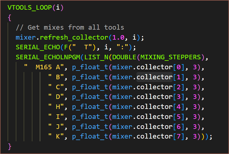
I saw that "collector" was accessible so I was about to make an entire vtool [ i ][ j ] array and function, but I remembered what the Marlin Coding Standards mentioned about trying to cut down on duplication. That's when I had the simple idea:
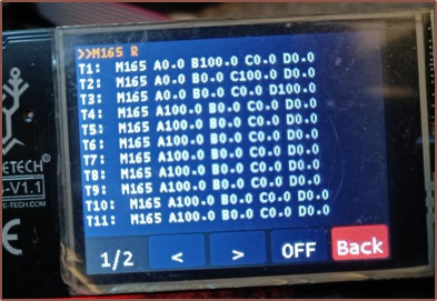
Soon after this snip, I decided that it would be faster to see and type in percentages than normalized values, thus I normalised the collector to show 100.0 instead of 1.000. I made a new branch before I did all the 8-extruder stuff in cr600s and compiled the code and this is what I got:
There were only 2 issues. T0 and T15 was missing. T15 was an easy fix.
T0? Well I was trying a few different things and looking in the code to make sure I'm doing the same serial commands as the other _report() functions. When starting one of the flashes, the OctPro almost immediately sounded its siren to signify that the 5V regulator couldn't sustain 5V before the system turned off as soon as it turned on.
Me: Hm? That's odd. *Turns off mains power*. *Looks around for anything that shouldn't be somewhere* *Turns on mains power*.
And then my PSU popped!
So after screaming "WOAUGH!!", smelling the classic pop smell in the air and checking to see if my SD card still read (as if it didn't would suggest that my electronics got fried along with the PSU), I couldn't see anything from the exposed-electronics side that could've done anything (the PSU side is enclosed).
Considering that I was actually expecting that pre-2019, old-school PSU (not the modern, thin and fanless kind, but the PSUs that had built-in fans and a 110-220V switch) to fry my circuitry the very first time I powered it on, I had hope that it was an isolated event (and not that something metallic found its way someplace detrimental).
I unplugged everything except the TFT24, which seemed to power on fine. I wasn't getting a connection with the OctPro, but that was fixed by flashing the firmware I was trying to flash in the first place.
So now I need to buy a new PSU, which will also change how the electronics box is modelled and how the OctPro is mounted. I think it's going to be very close with 1 metre extruder cables.
Fixing the missing T0
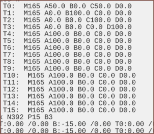
As it turns out, this was never missing:
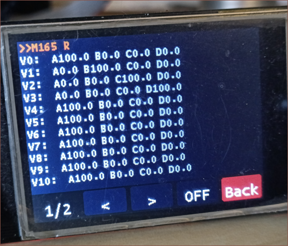
As you can see, however, there's a lot of "T:" stuff that usually goes through the serial window, so I hypothesised that the touchscreen firmware was just ignoring the first line because it was "T0:". After some testing, it was actually the substring that was the issue, thus "VT0:" wouldn't work but "V0:" would:
Future work
So to get here took 12 hours total. I can see why Me In The Past has left "repair CR600S" on the todo-list for years.
The next part of this saga is now going to have to be getting the TFT24 to use this in a useful way. My main strat is to get some kind of new printing menu that shows the mix of the currently selected v-tool. While I'm at it, I'd like to implement the large 2-digit, estimated time remaining display idea I have. Like I've already mentioned in #SecSavr Soapavr [gd0146], if everything is working reliably, all I care about is the time until the print is done (or the time until a user action is required) and if there's an error.
- Seconds 01 - 59 in lime green (to alert that it's almost done)
- Minutes 01 - 59 - white
- Hours 01 - 71 - bottle green (same as CR600S and most likely to be)
- Days 03 - 99 - Probably blue? It needs to be a colour that is visible but unobtrusive as it'll be visible for a while.
- Surely there's not a single print that takes over 99 days.
-
[R] 42BYGH24S Nema17
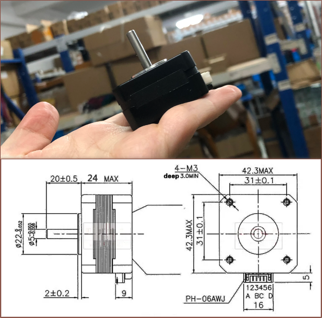
02/21/2024 at 06:28 • 0 commentsProduct Page Unfortunately, AliExpress search isn't what it used to be. It really takes some effort to find things, even with AliTools assistance.
The good news is that this motor is claimed to be 24mm and comes with the cable terminations I'm looking for, and it comes in over £1 less than the 17HS4023 motors I found, thus £31 before VAT. It's also allegedly 0.24Ncm, which is twice the 0.13-0.14Ncm of the 17HS4023 motors.
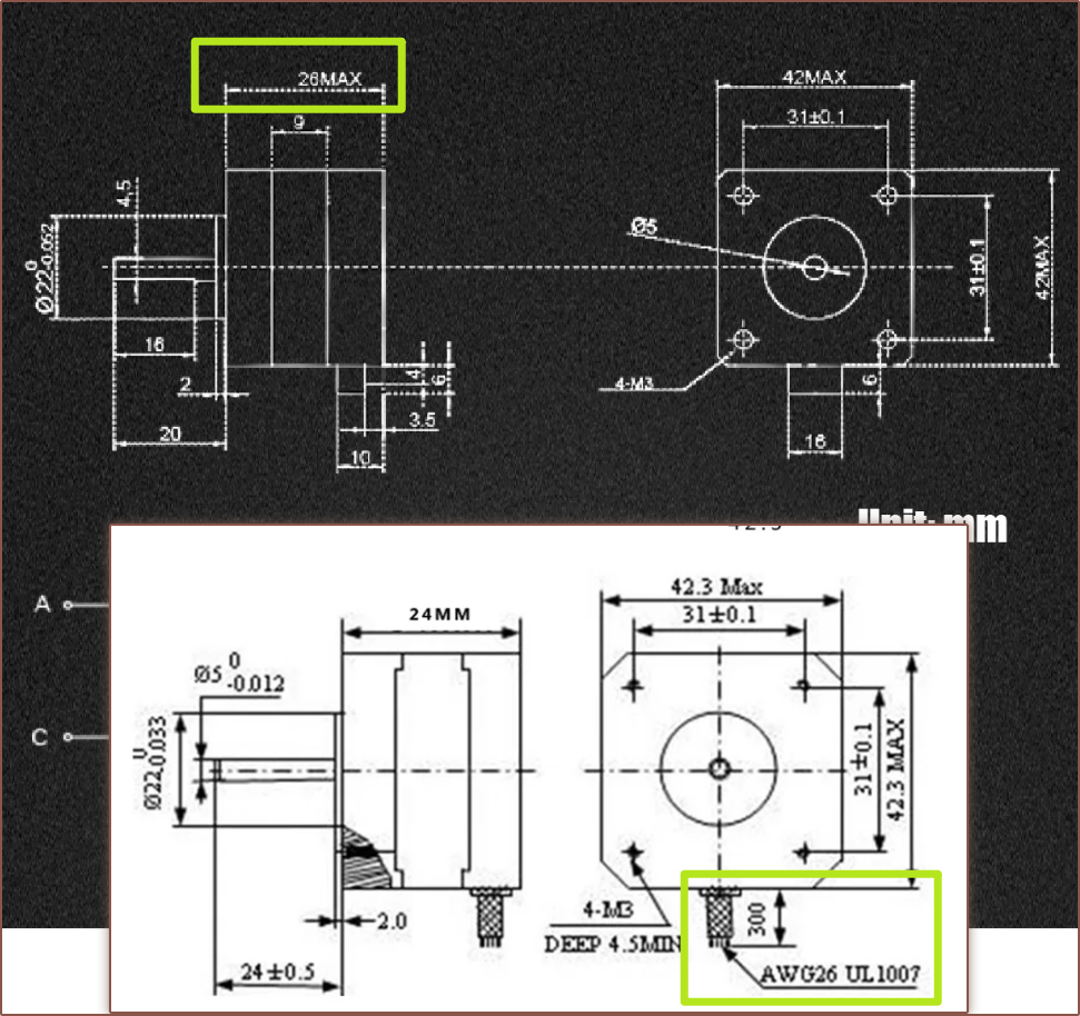
The bad news is that there must be 2 different motor drawings on the listing, and the motor in the image is like the superposition of them:
Continuing to look through Reverse Image Search, it seems the seller also has 3pc and 5pc listings, the latter has both an image of a worker holding the motor and a drawing that seems to line up with all the claims:
-
[E3][M] Coaxial8or logotype and test model
02/20/2024 at 10:00 • 0 commentsThe finished logotype So I was idly thinking about the potential name of the 8-in Printed Coaxial Hotend, and one thought that popped up was "I'm sure you could make a trendy and techy logo with a name like that.". I was intrigued, and after about 6 seconds solving the solution, I had this circular typeface idea and just had to see it IRL.
How I got to the logotype
So I sketched my idea out in Fusion because I knew it was going to be one of those constraints-based logos. Extruded out the profiles and the negative space dismantled my initial idea:
That was simple enough to fix with a circular outline around everything. I also reduced the spacing so those outlines merged together. This also allowed me to have a negative space where the A and L intersected. Next, I experimented with the dots that I wanted in the design to convey the "coaxial" part. I tried 0 dots (didn't like it), A dot in each o-shaped part, dots in the last 4 characters (as I thought that the L and R could also signify how the inputs actually curve around the internal coaxialiser) and 8 dots (one for each input).
While the idea is nice, the dots just made the logo look excessively complex. I mean, yes, the internals of the actual hotend also look excessively complex so it ties in, but logotypes need to be easily legible.
It also took a while to decide on the L and R design as the circle outlines weren't that legible. Notably, I tried 90 degree lines for both, or a 45 degree R bend before settling on the design at the top of this article:
Conclusion
Other than putting this logo on the empty space of the hotend cover, this logotype probably isn't going to do much. It's interesting that this project basically jumped the queue as I've been meaning to make #Tetrinsic [gd0041] and #SecSavr logos for months/years.
I might also make a CR600S in the same style (or find a circular typeface so I don't have to try modelling it).
Test Model Idea
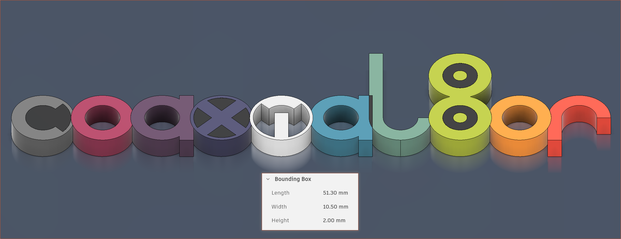
[11:10] So, about an hour ago, I concluded that I wasn't going to do much with the logo. Only moments after publishing did I have the idea that I could have an 11-colour test model:
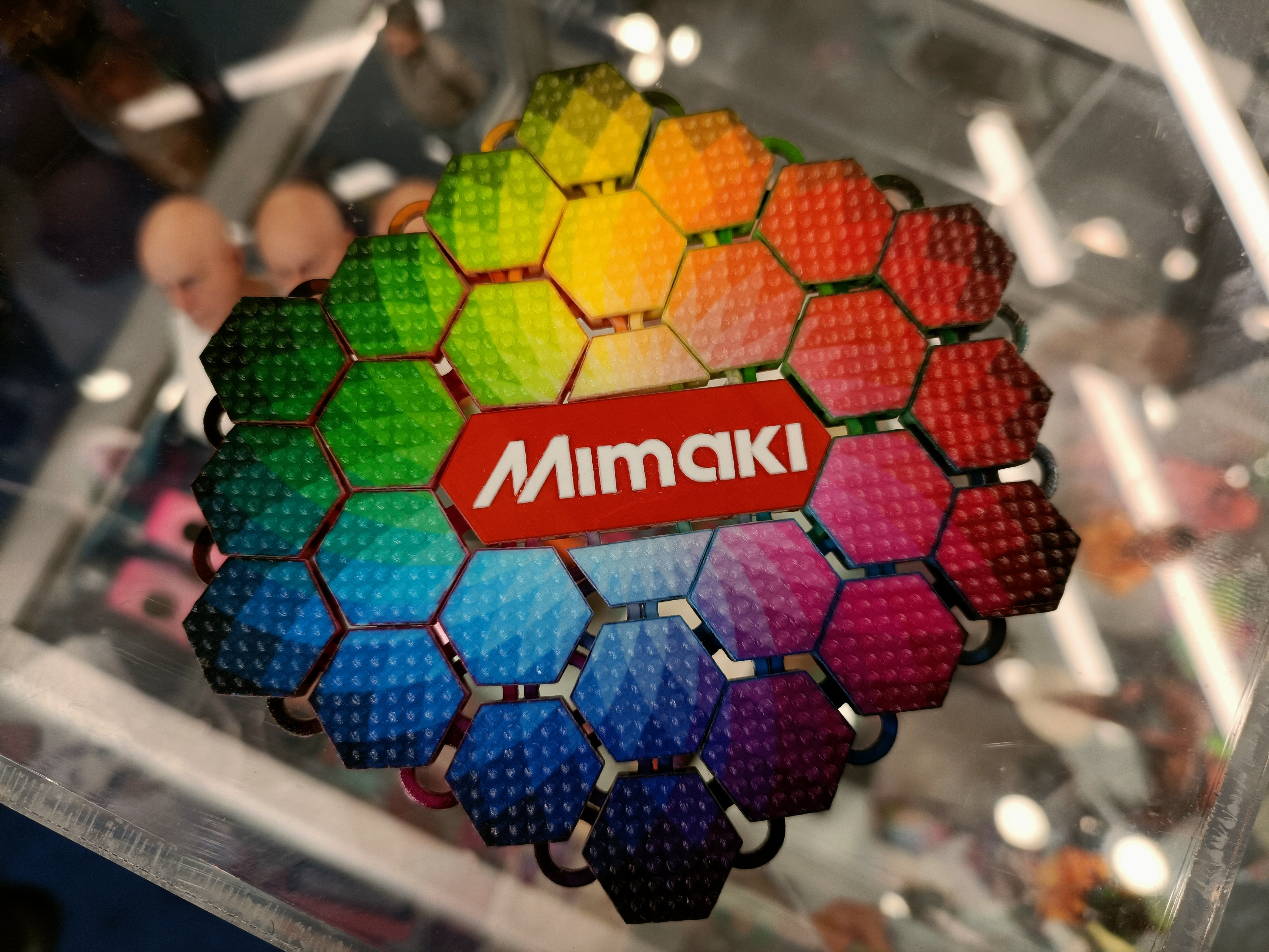
I've just realised that the thinnest walls are only 0.3mm, so this would actually need to be printed 2x larger for a 0.6mm nozzle. Think of it similar to a Mimaki or Stratasys demonstrator model:
An image I took back at TCT Birmingham 2022. I just chose some colours that I'd like to test out for the first couple of prints:
- I like dark greys
- I thought the i would look pure and internet-like if it was white
- the L is the milky-green I'm trying to obtain
- I thought having more muted colours for most of them and then vibrant colours for the last 3 characters was a nice idea.
- the purple is bq Aubergine and the dark blue is YouSu's Galaxy Blue.
- I thought an LED-matrix-inspired yellow-green 8 against black looked nice.
At first, I'm likely just going to be doing gradients between 2 colours.
I guess for those that use American English, having "co" "l" "or" as coloured and everything else as greys is also an idea:
Surprisingly versatile! [12:00]
Just added a nice brushed, dark metal background:
[13:30] I think an inverted X looks to have more depth (like the XBOX360 logo). This is 3D printing, after all.
Thus, the 2D now becomes:
[19:30] Haven't seen the logo for a few hours and thought that the dot of the ' i ' could be more legible instead of being in a superposition between ' i ' and ' T ':
In the test model, I've gone in and made the ' x ' a tad brighter and searched up the actual "bq Aubergine PLA" because the colour I chose looked slightly (but annoyingly) wrong. I feel that the tweaked colour is a lot closer to the true colour.
[21 Feb, 05:45] This modern and rounded logotype wouldn't be my first guess for a name as edgy/gamer as "Coaxial8or", but it seems to be rather fitting after giving it "six seconds" of thought, as I said yesterday.
-
[M] More ideal extruder mount
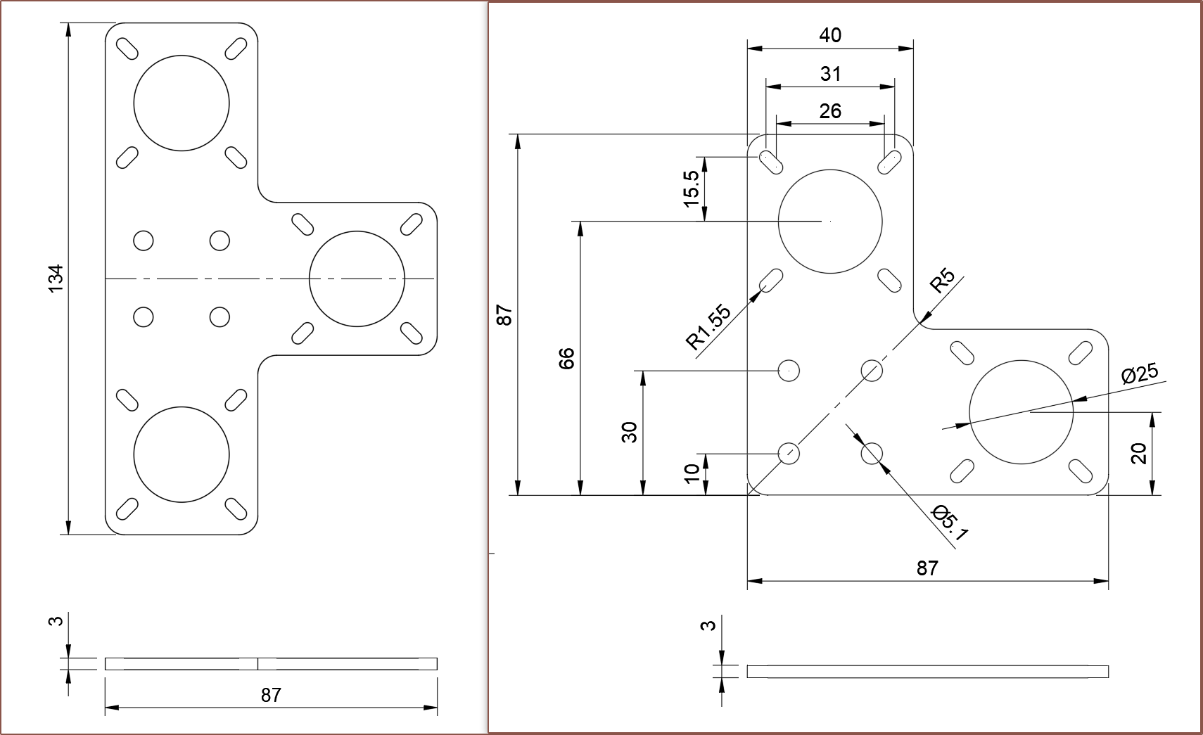
02/20/2024 at 08:00 • 0 commentsSo I was looking in my basket and realised that £8 is going to the Nema 17 mounts, and they're literally just aluminium plates. I thought "What if I asked the uni technicians if they could make this." which was soon followed by "Why stop there? I could 'double my money', so to speak.". In this context, "double my money" means "double the amount of extruders mounted onto one plate".
It took 6 minutes in my mind to think up, but one entire hour later, I had modelled and dimensioned a solution. This doesn't include the time I spent modelling the original mount for use in the #SecSavr Sublime [gd0036].
Tri Mount on left and Dual Mount on right. The plan is to have 1 Tri Mount that holds 2 motors and mounts onto the CR600S and then another 3 Dual Mounts for the remaining 6 motors.
-
[M][A] Switch to 17HS4023 Nema17?
02/20/2024 at 05:55 • 0 commentsThe lowest I've found at the time of writing is about £32 for 8 motors (before VAT). The reason for this change is because I still haven't gotten a response for the seller of the other motor and, while waiting around for one, I noticed that the connection socket looked longer than usual. That's because it actually is:
These 23mm motors come with their own cable, but since it's Dupont-terminated, I'm likely still going to get XH-terminated cabling. Dupont seems to work fine on the 4-in CR600S though so perhaps I can save £3 and just make sure they're cable-tied in place to remove the risk of a loose connection. Nah. It's £3.
Another benefit is that this motor is much more common, meaning that there's a higher chance of reproducability.
I've designed a 4mm spacer so that the motors can be mounted onto 2020-series 4040 extrusion:
I'm going to see if I can get it laser cut in 4mm acrylic along with the 1mm PTFE.
Surprisingly, the BOM doesn't change all that much at all.
-
[T] Potential name: Coaxial8tor
02/19/2024 at 17:43 • 0 commentsAs you may understand, the name "8-in Printed Coaxial Hotend" is a bit of a mouthful and doesn't roll off the tongue or anything. More importantly, if this actually becomes a new class of hotend, then the name would be too generic; it would be like a project called "Dual Extrusion Hotend" or "Large Gear Extruder". I was never shy about the syllable count, and something called "The Enraged Rabbit Carrot Feeder" exists.
Well my mind was just idly thinking and it connected the dots with other name styles in the industry, such as:
- Slic3r: A 3D slicer name that is supposed to look like "slicer"
- Construct3D: 3D printer company with the play on "constructed"
- SLAminator: SLA 3D printer with washing+curing built in
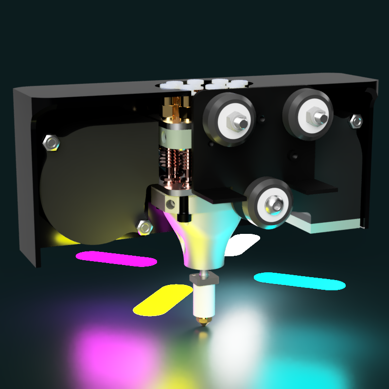
The end result is the name suggestion Coaxial8tor that is said as "coaxialator" and uses the number 8 because it has 8 inputs. I think it's a fitting name considering how complex the inner pipework is and how printers with more than 4 extruders are few and far between currently, thus a hotend that does double that is quite... extra... and should have a name to match.
-
[A] Heatblock ordered and 1mm PTFE gasket
02/19/2024 at 14:50 • 0 commentsHeatblock ordered
Hours of modelling, thoughts, issue mitigation strategies and error checking has finally got this project to the state when I could finally send my 2nd attempt to PCBWay to manufacture.
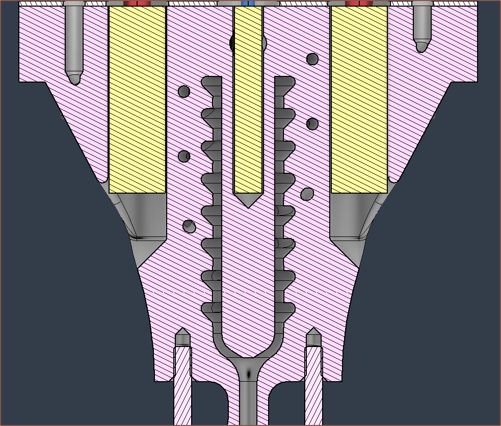
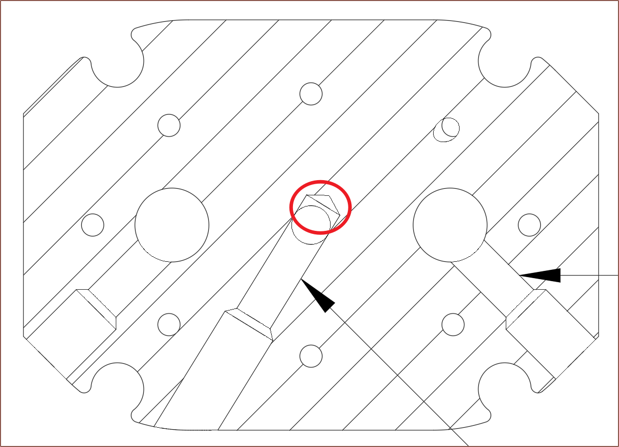
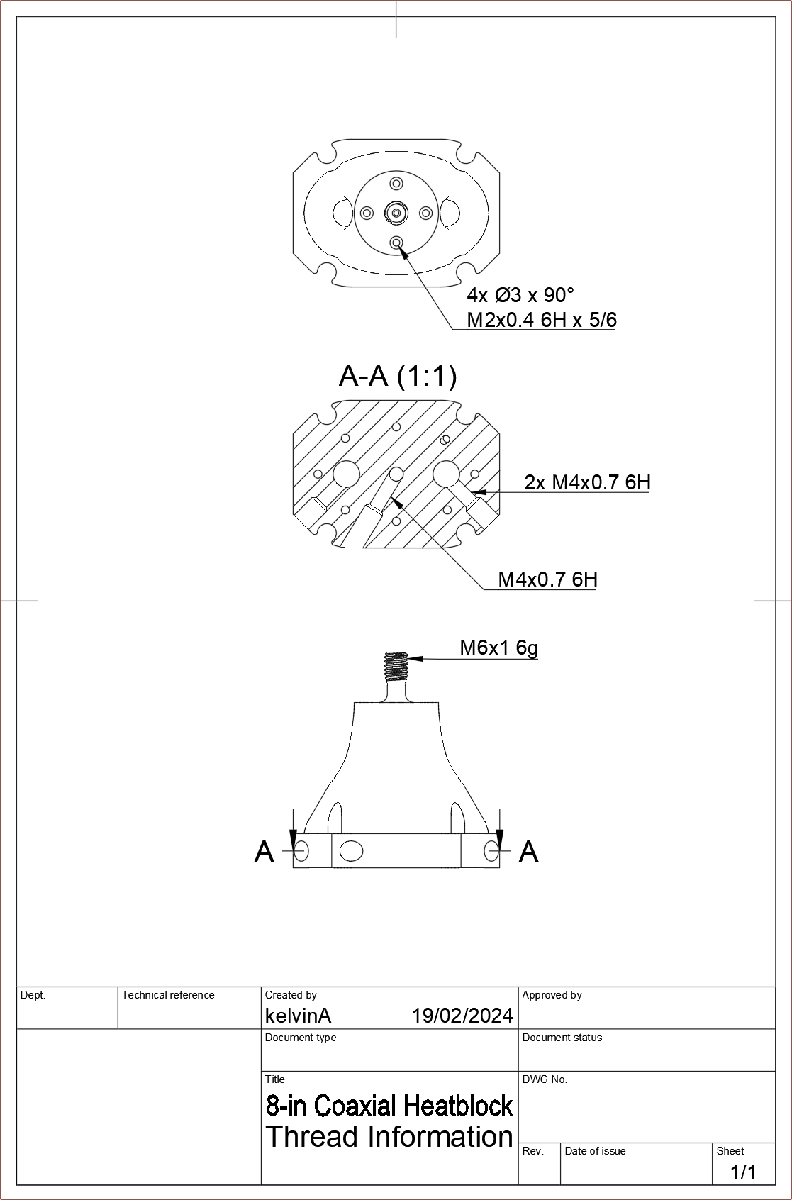
So I woke up this morning and decided to make a Thread Information Drawing. Whilst doing that, I decided that the extra depth of the thermistor grub screw hole (circled in red in the image below) didn't really need to be there. Me In The Past added it in so that there was enough clearance. Now I'm thinking that "If it's needed, the technicians could drill the extra material away. If it's not, now there's less contact area that the thermistor could've had" and so removed it. It was also in an effort to prevent supports in hard-to-reach locations.
I also uploaded this thread information just so that the engineers were aware of them, even though I'm not asking PCBWay to actually tap them. "Maybe they might adjust the holes to the ideal size for AM" is what I thought.
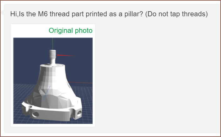
In practice, it seems to have caused a bit of confusion over at PCBWay, since I checked "No threads" but also gave thread information, and when I said that "I just need the M6 that is in the CAD file" (trying to mean "Don't turn the modelled threads into a cylinder."), they thought that I wanted that single M6 threaded:
The quote. My reaction to the quote. I cleared up that misunderstanding, but after paying for the order with the expected $64/part ($83.66 with shipping + card fee), the misunderstanding I was trying to avoid surfaced anyway:
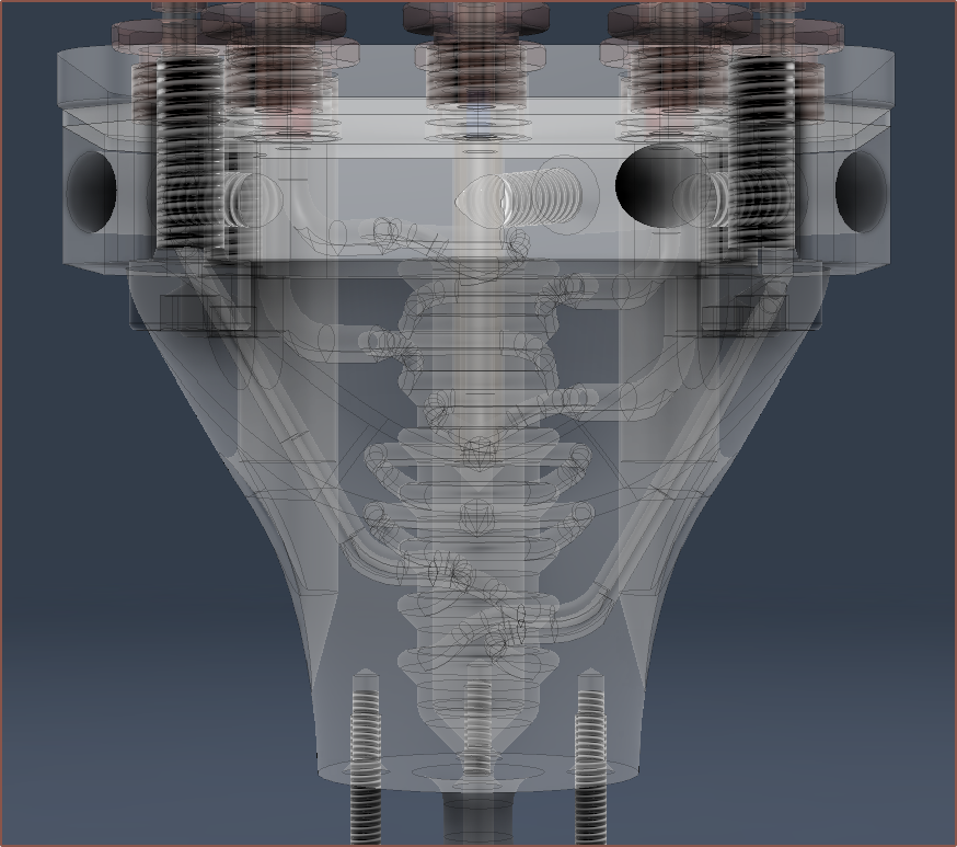
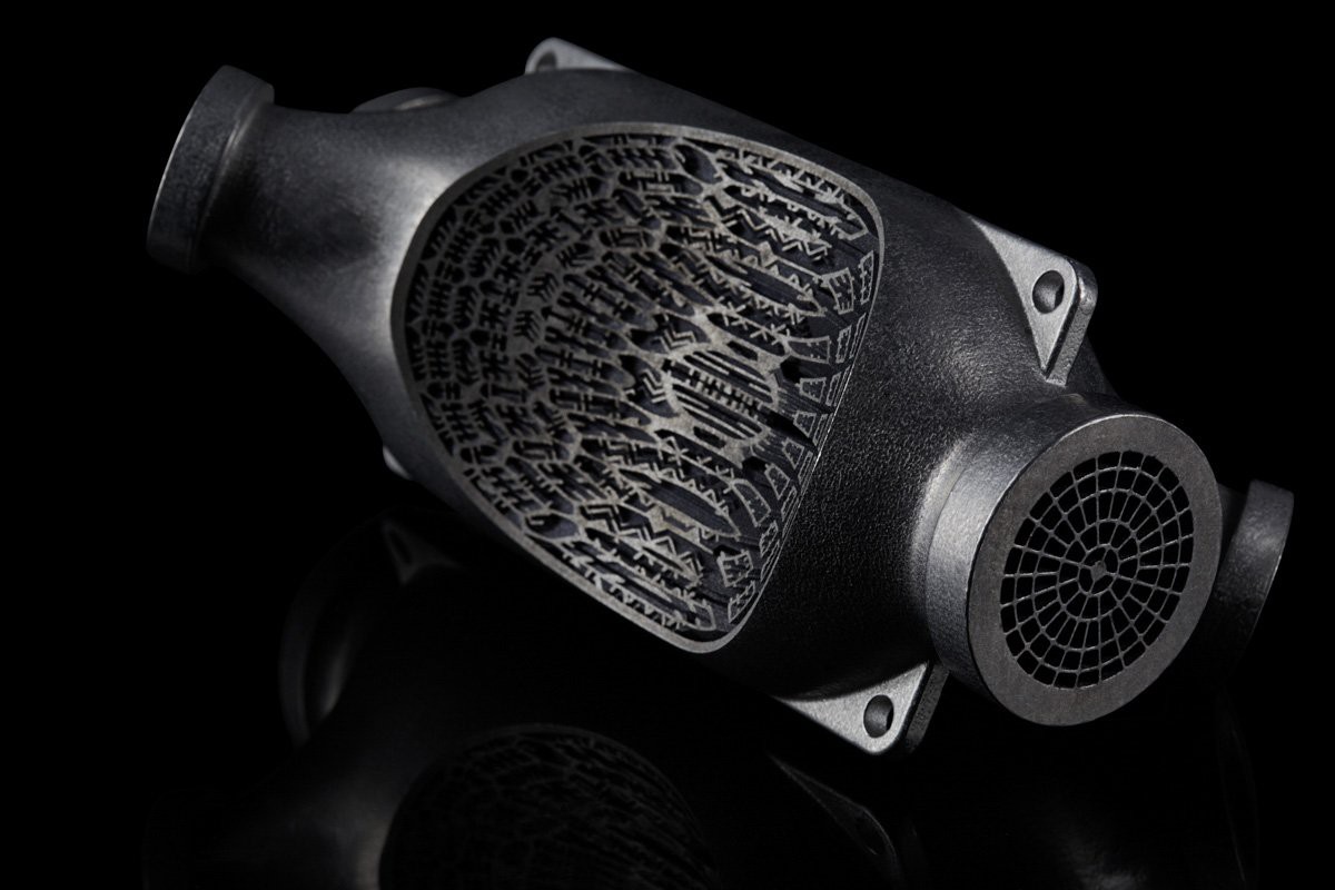
So, like with the first attempt, I'm expecting that I'm going to need to be checking in daily just to make sure that this design gets through. I do wonder how long it took for engineers to create those super complex heat exchanger prints that the industry likes to demo as an AM metal application:
It did feel a little rushed when I actually bought the thing, which I'd describe as a similar feeling to wondering if the door was locked when leaving one's location of residence. I had to keep reminding myself that I spent at least an hour yesterday and at least another hour today combing through to find any last minute bugs / mistakes in the CAD.
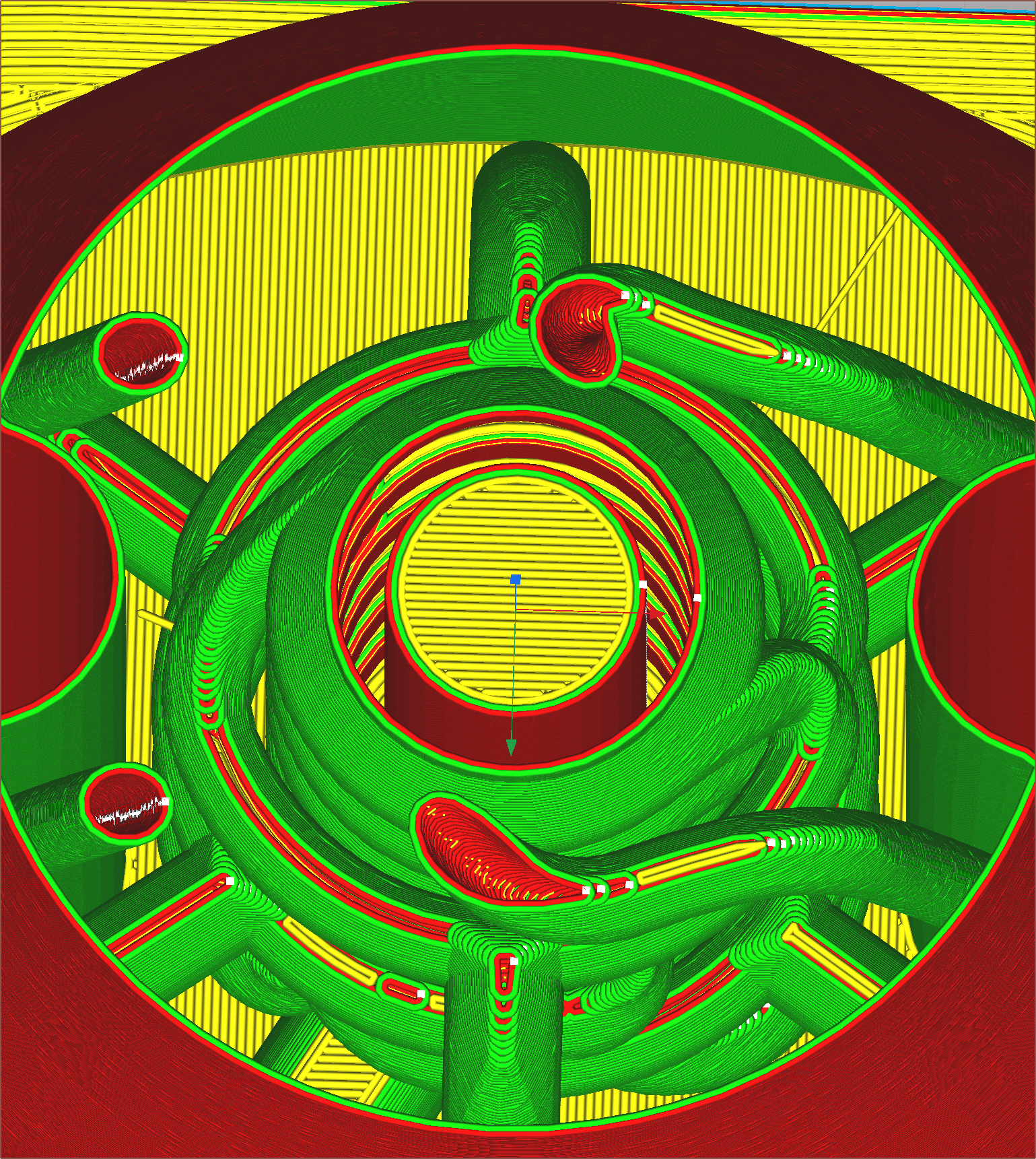
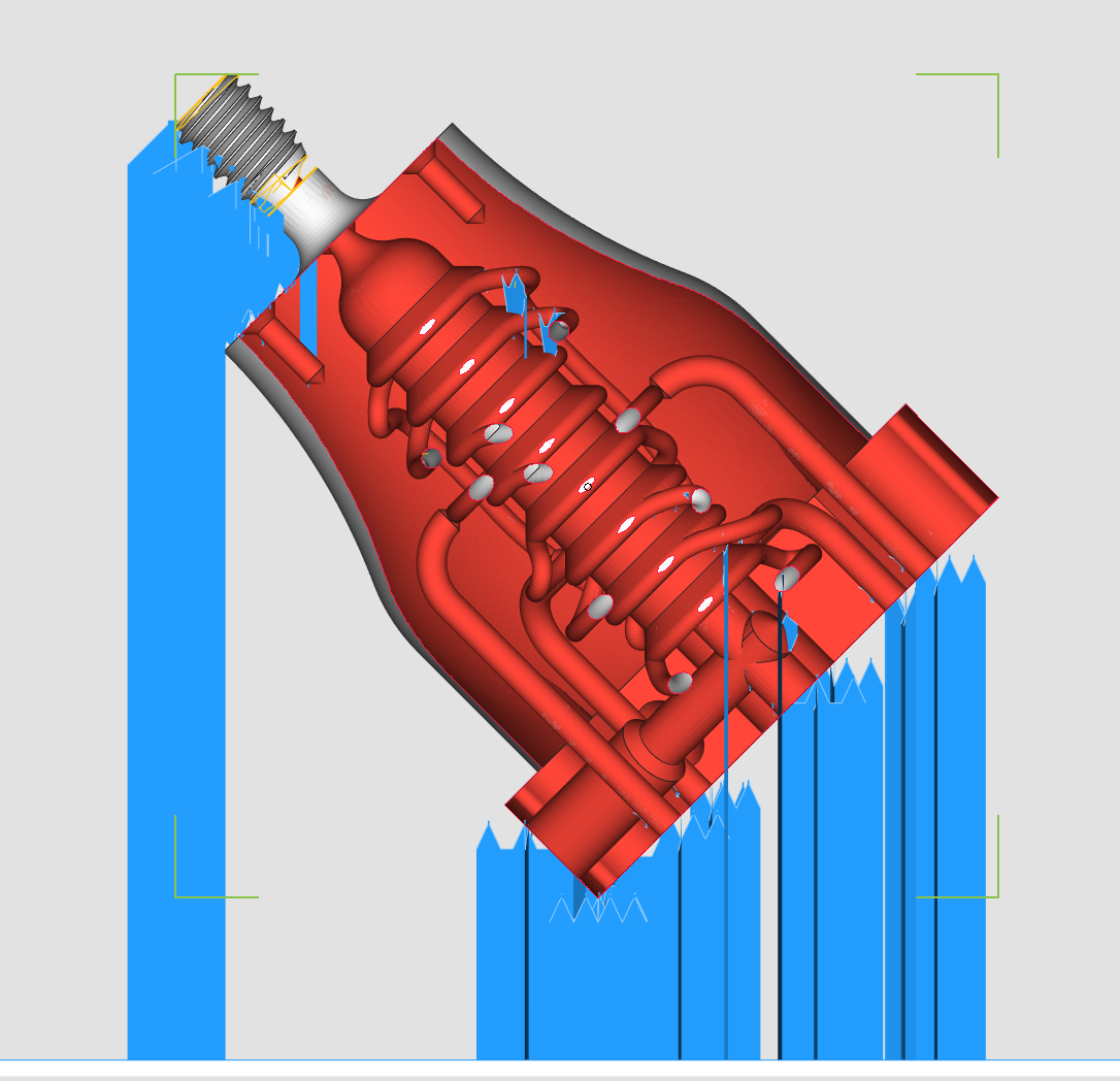
I put the file though Cura yesterday so that I can more easily look at the layers. Gasket
I'm going to see if I can use the laser cutter my uni just happens to have to manufacture the gaskets. I'm also going to use 1mm PTFE instead of 0.5mm silicone as it should be stiffer and have a higher working temperature. Also, I could get some for £2 locally instead of £3 from AliExpress.
Additionally, while the recommendation for gaskets is "as thin as you can", thicker is used to mitigate issues due to the imperfections of the real world. Basically, there are more potential issues from going too thin than too thick. Even with that said, 1mm is still a rather thin gasket, but thicker than a business card so should be less floppy and easier to assemble into the hotend.
-
[M] Heatblock design optimisation
02/18/2024 at 12:34 • 0 commentsOn the 14th Feb, I was looking to send off my most recent design for a quotation and I noticed that it was mostly unchanged since the 3rd and believed that I could optimise some things.
Optimising some things
It didn't take me long at all to find this minimum wall violation:
So I tweaked it so that, in theory, less material would be needed for the hotend and the filament path would be shorter:
Then there was a violation inside the actual "coaxialiser":
So I fixed that as well as the minwall violations for the heater cartridges:
I got a preliminary price of about $53 and mentioned the internal channels in the notes just to make sure the engineers were aware of them. I had only dropped maybe 6g so those are some expensive grams.
Somewhat concerned about the expected heating times if there's almost double the material as the 4-in. Me: I've gone through and optimised the design. If it was OK before, it should be smooth sailing now and with a lower price too!
PCBWay: I've got issues with all of this, this 'n' this.
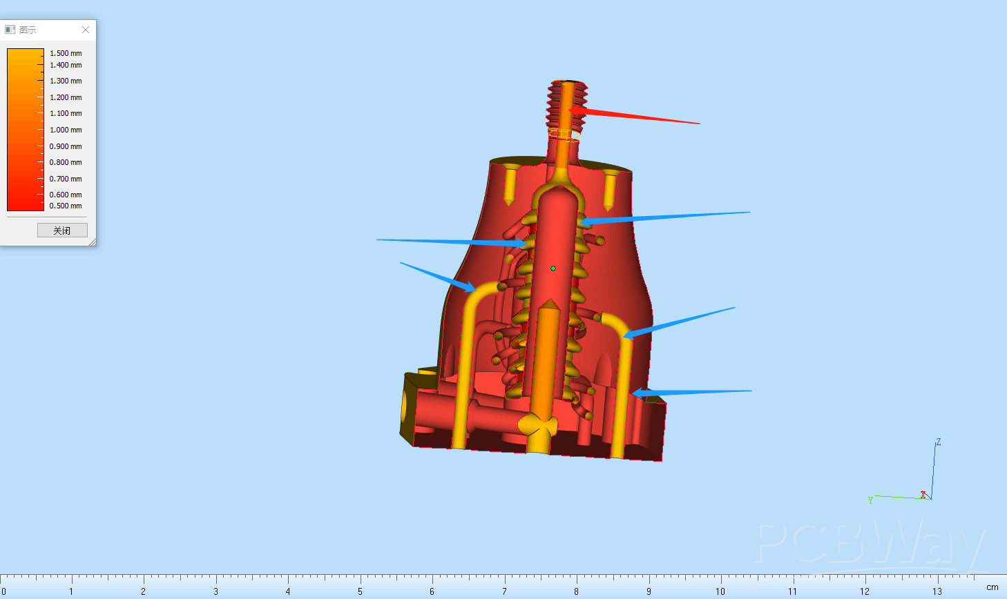
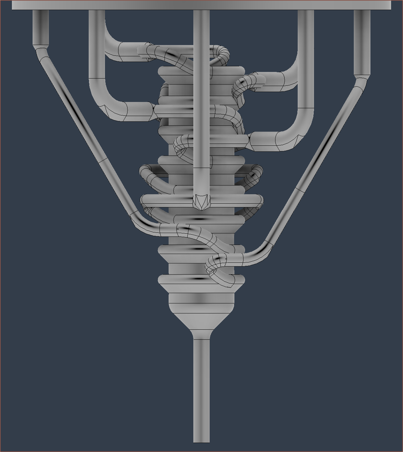
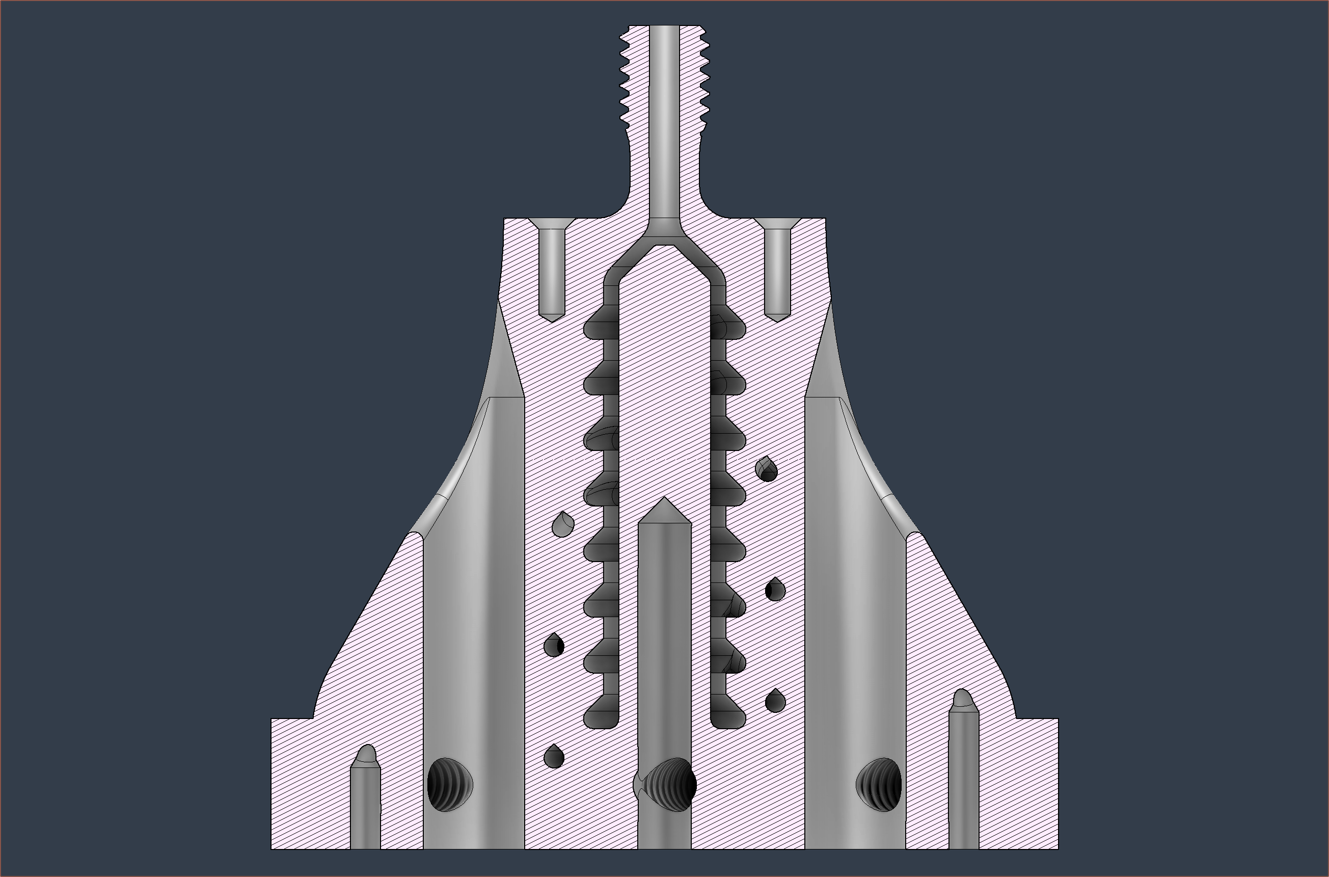
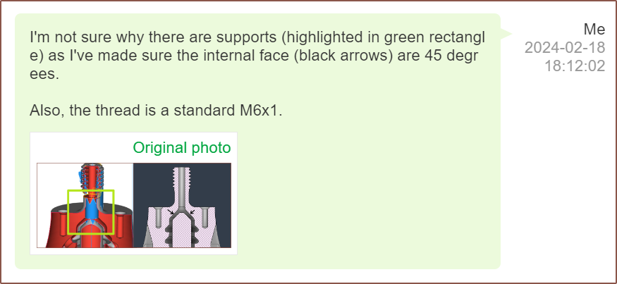
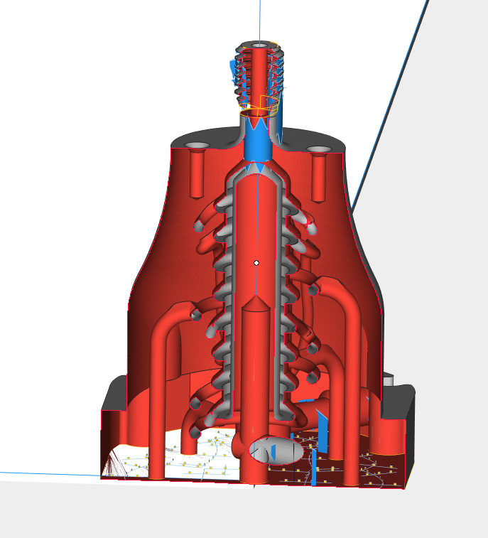
The arrows show locations that unremovable supports would be, so I'm told. This is what I found on the 16th (2 days ago) and I expected that I actually had to model in the raindrop-shaped overhangs throughout the design. Today, I woke up and attempted it, but first told Eleven (my PCBWay agent) my plan. Partway through, she said that wouldn't do anything as there'd still be internal supports. Confused, I asked to see what supports are actually being generated and I got this:
Assuming that they thought I meant "why not just rotate the part 45 degrees" instead of "I will replace the overhangs with 45 degree faces", I continued.
Modelling 45 degree overhang eliminators
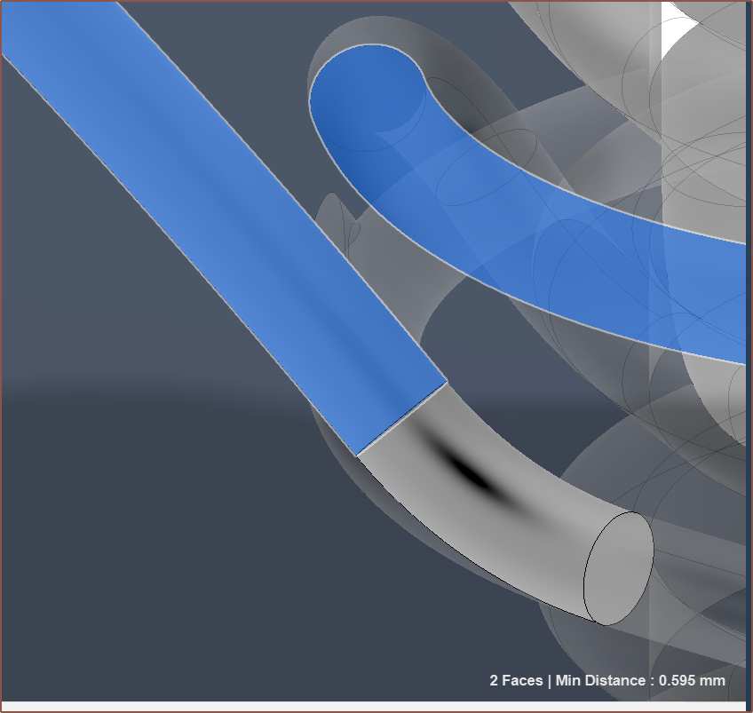
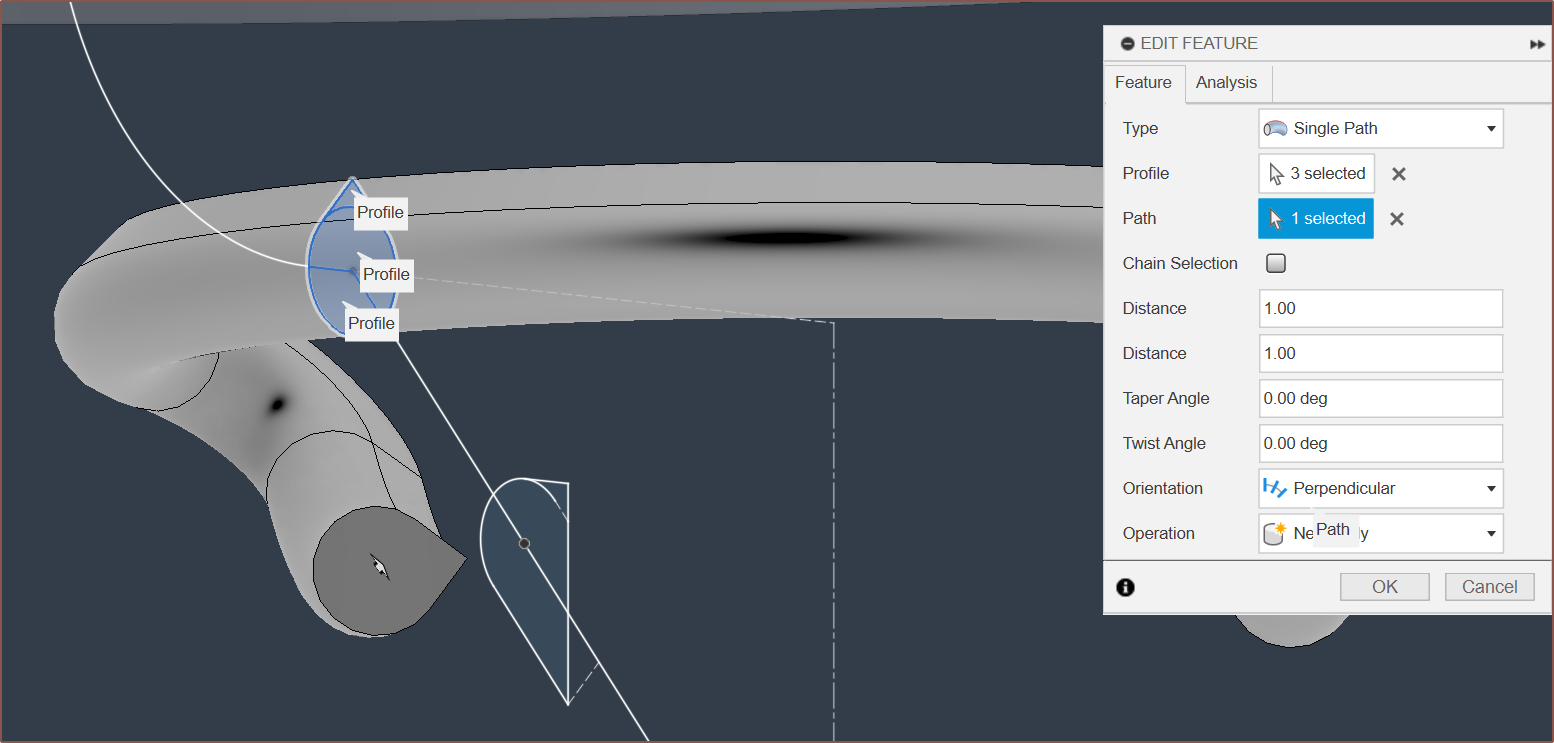
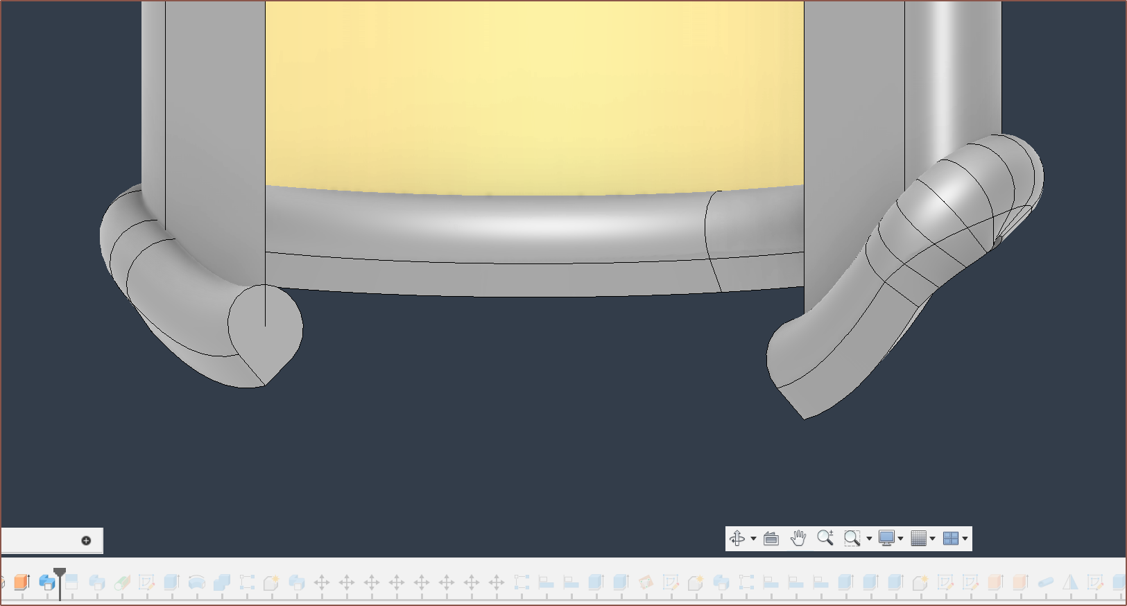
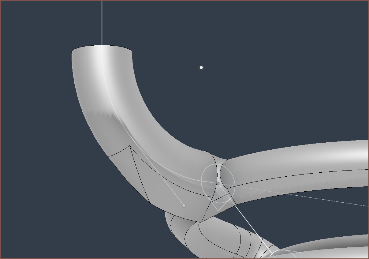
So as you may know, curves will cause the profile of sweeps to rotate:
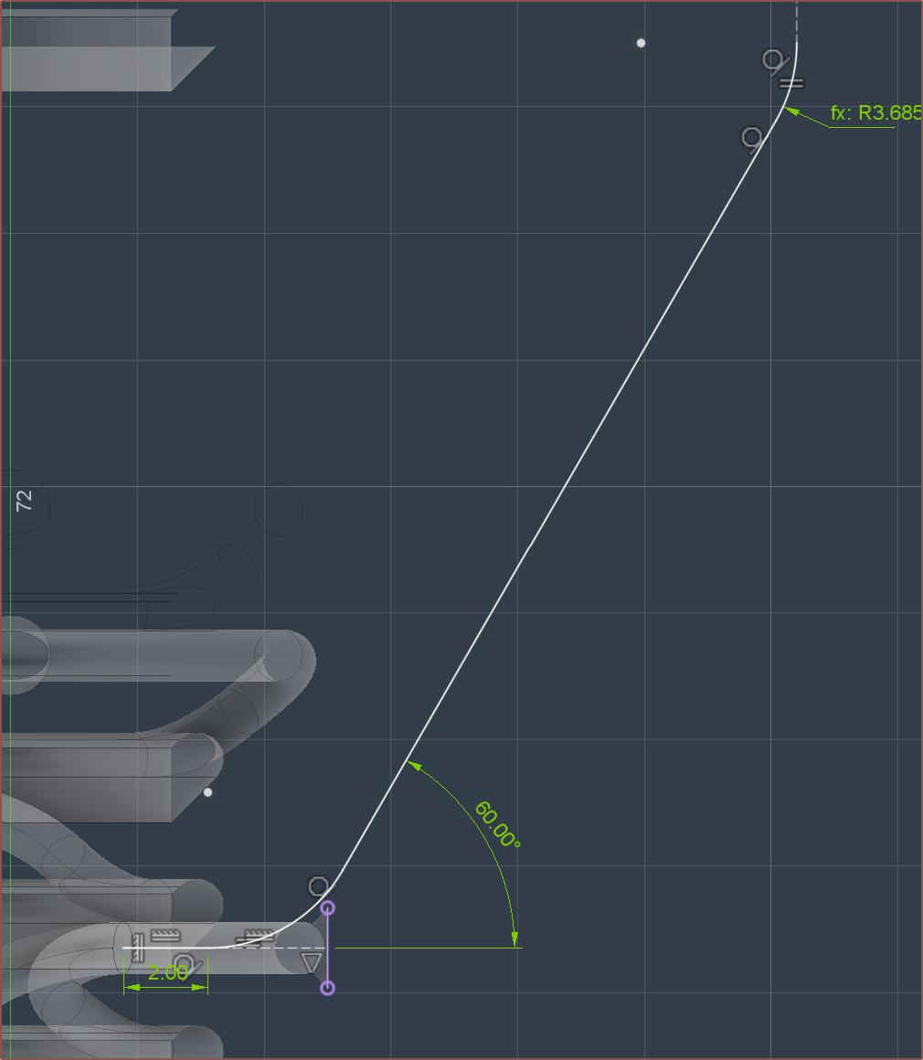
It didn't know of any option Fusion had to keep the profile orientation the same. Thus, I went to r/Fusion360 and searched "sweep" just to see if there is anything I can learn from others that had their own sweep issues. From the solution video from this post, I learned that there are more than just "Single Path" types of sweeps. I successfully tried a few things and the simplest solution was to use the "Single Path + Guide Surface" option, whereby my construction surface is also used to keep the orientation the same:
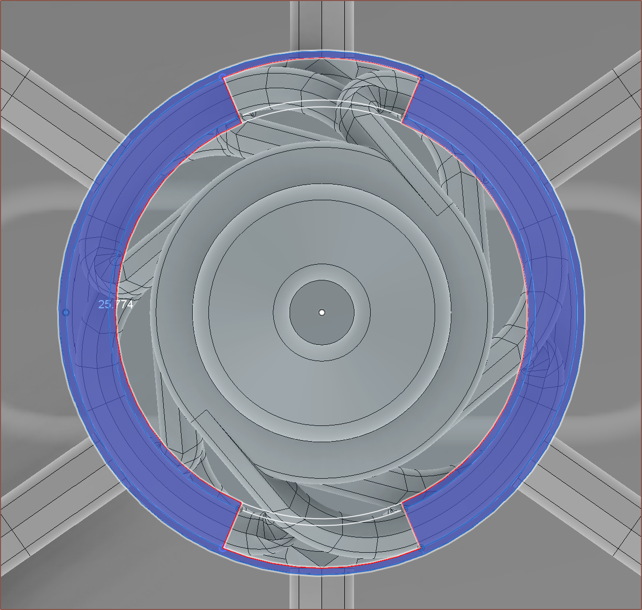
Next were the MajorChannel ports, which took a loft of half the profiles, offset face, delete face and some sweeps to get the result needed:
I had to have a 0.01mm flat section at the bottom since the loft tool wouldn't like it if 2 rails shared the same point:
Some more cutting and trimming and trimming and cutting later...
(such as having to do this cut manually to remove extra geometry for the last 2 inputs instead of letting Delete Faces handle it) ...I had a new solution:
This is the Buildable:
Other than some mystery supports that hopefully don't need to be there, I think it's good to go.
I guess if I squint, the supports might be for something else? Trivia
The part cost is $64.38 which is the same as the alpha-build I had quoted to see what kind of price-range this strategy would be in. The final cost is $83.66, which converted is a fractionally-round £66.67.
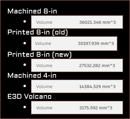
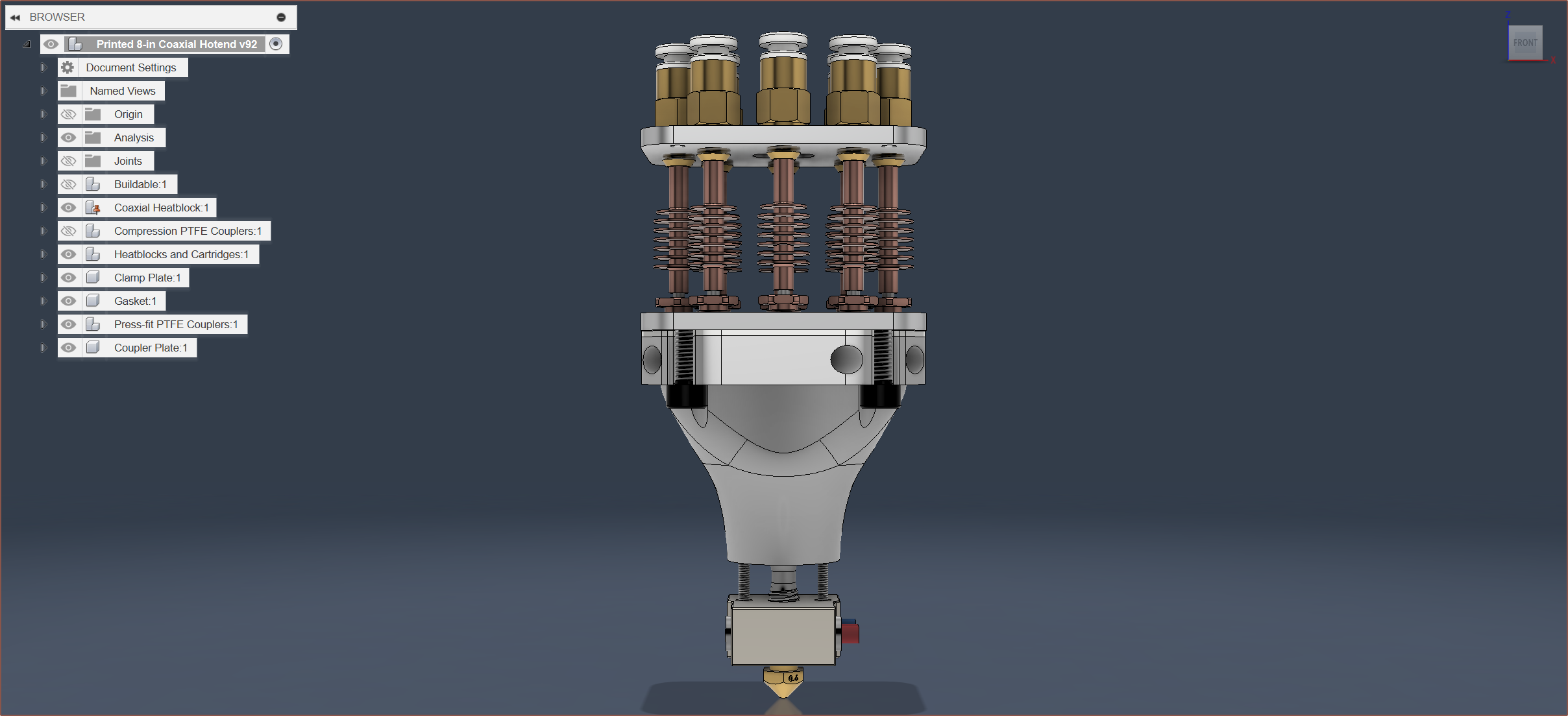
The volume is approx 27600 mm^3, which is 8.7X more than a volcano block. Thus, the input:volcano-volume ratio is 1.087 for this 8-in-1-out hotend, which is slightly lower than the 1.133 for the 4-in-1-out. It's interesting how this project both figuratively and literally tries to merge multiple hotend tools together.
-
[P][M] Plates manufactured
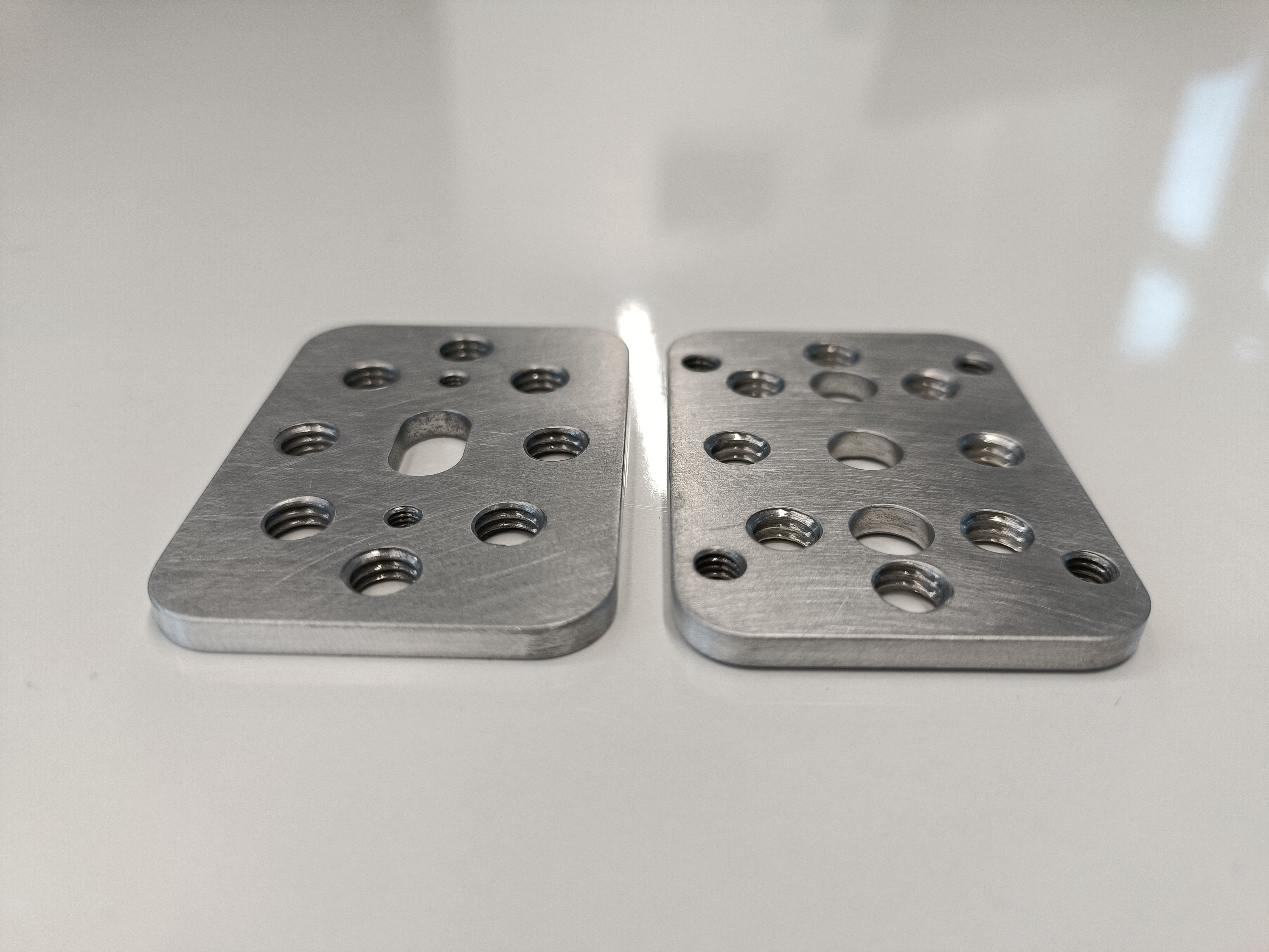
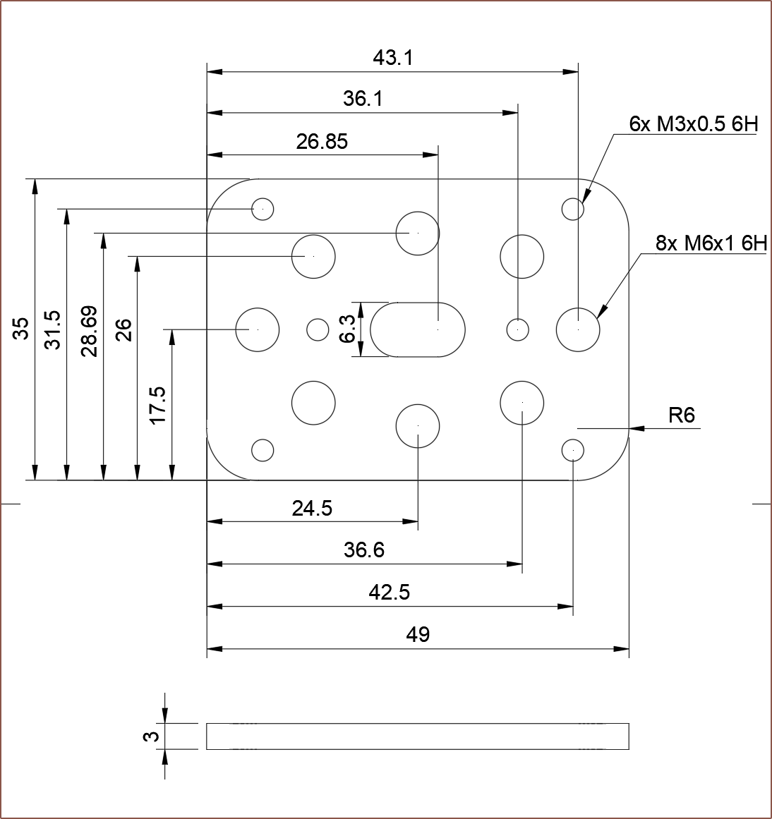
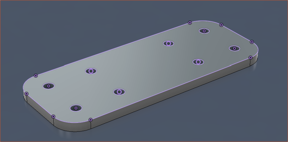
02/15/2024 at 18:21 • 0 commentsCoupler plate (left) and Clamp plate (right) [18:20] I was worried about the proximity of the cartridge holes and the wall thickness of its adjacent thread, but the technician had no issues to report. These are both 3mm plates.The coupler plate slot might be a bit more of a squish than I originally thought because I didn't account for the thickness of the cartridge wire protective sleeving, but it should still work fine. The cartridges fit through so I don't have to desolder and resolder anything just to install/remove them.
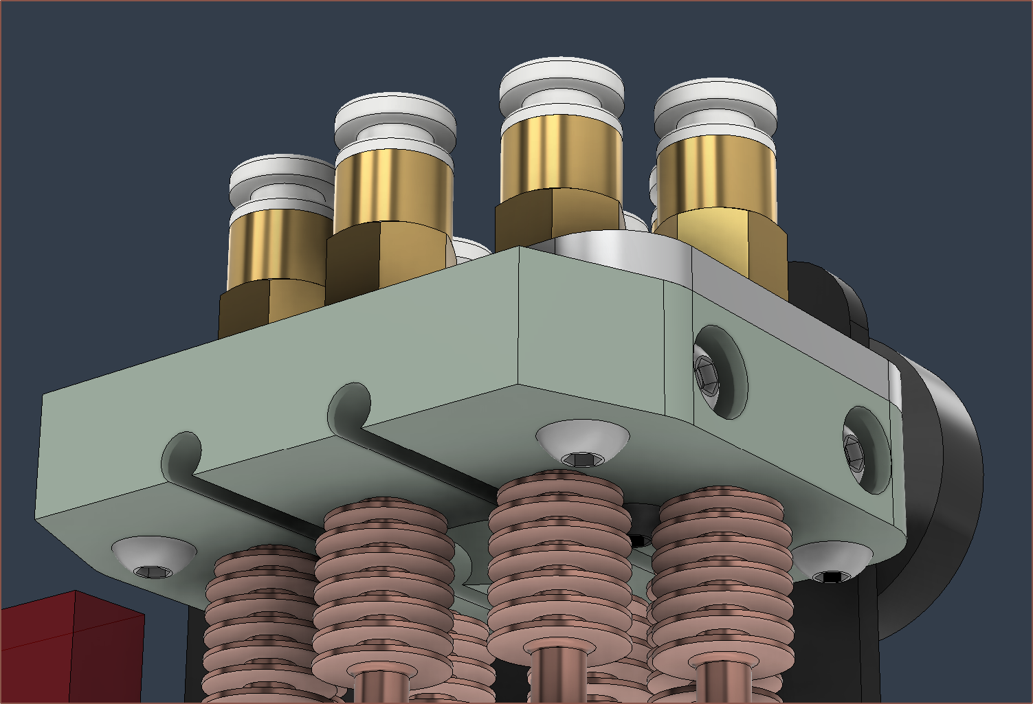
I'm glad I had the foresight to even design the coupler plate instead of trying to make some 3D printed part that either held in M6 nuts or (if they even exist) heat inserts. Like the heatbreaks, there isn't a lot of thread on the PTFE couplers. This way, the end product looks better, the couplers are less likely to bend/break off and-- ohhhh I knew I was forgetting something. I've just realised that Me In The Past also wanted the plate to act as a stiffener for the printed holder.
[18:50] Modelled some M3s in:
The top looks less sleek, but in practice you'd likely never see it:
-
[E1][T] Directional fan and new filament strategy
02/12/2024 at 09:59 • 0 commentsPart cooling
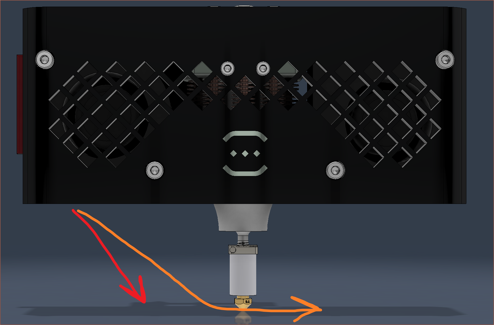
I'm hoping that I can actually just further direct the fan air so that I can have an open, ductless hotend. The red arrow is the expected current air direction (from feeling the output air stream) and the orange is the ideal air flow with a duct similar to a tower fan or car AC.
Filament Strategy
The Aesthetic Series
I've also considered a new solution of filaments and their order:
- White
- Also used for cleaning/purging since it's readily available and white PETG/PLA/ABS is less flexible than cleaning filament thus easier to extrude.
- Silver / Stone
- Silver: A bright silver material for creating silky or metallic-looking materials like copper, gold or car paint.
- Stone: A white, mortar-looking material for creating rocky materials like brick, sandstone or concrete. This may need the fuzzy-skin slicer feature to make it really look like stone.
- Black
- Moved to before the CMY colours so that it effects subsequent colours less during changes.
- Yellow
- Magenta
- Cyan
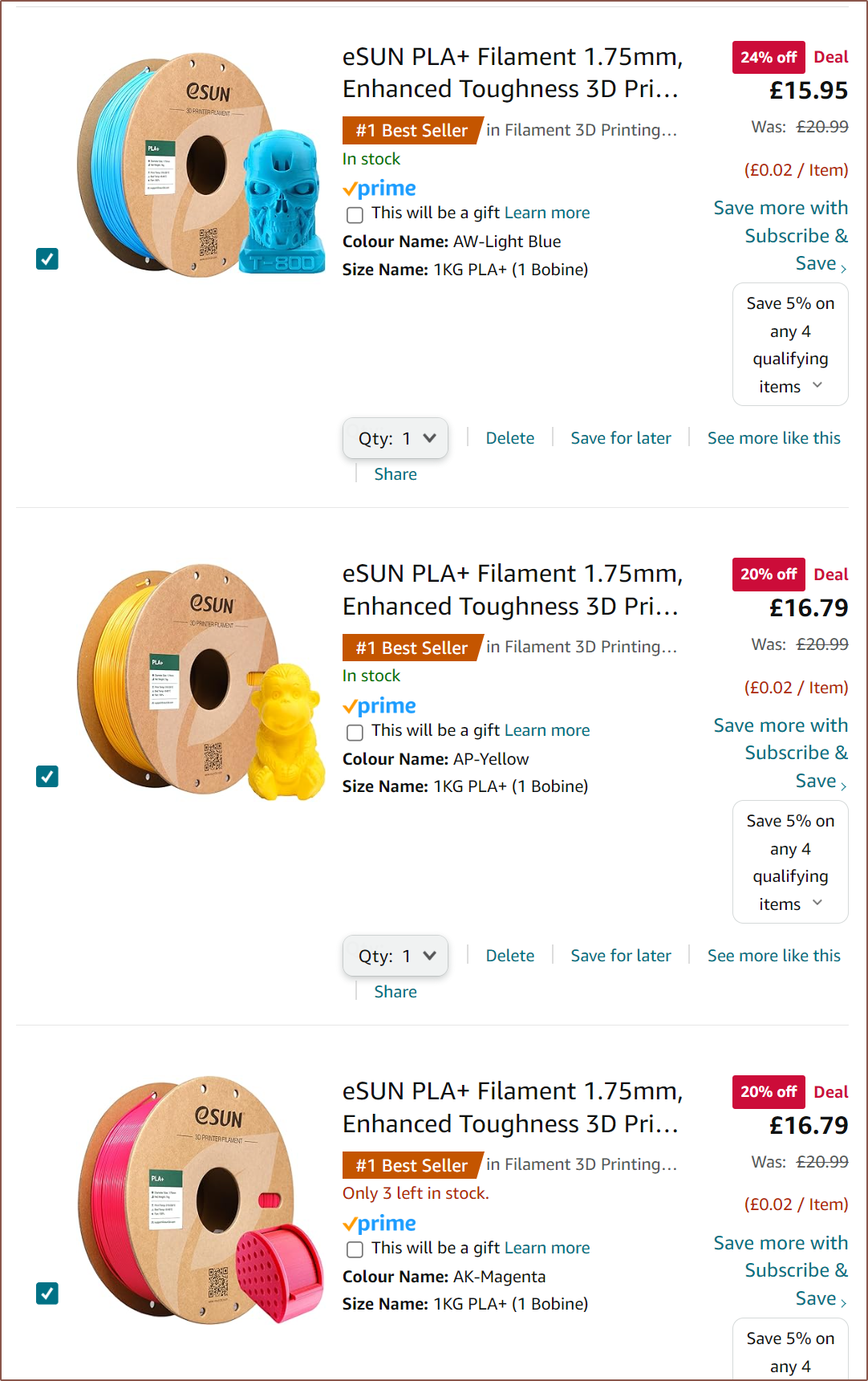
- Potential CMY filaments from eSun:
- Transparent
- This is also so matte or glossy materials can be created. If the other materials are glossy, this would ideally make the final filament look matte.
- [Edit 1 - Feb 22] However, for an alpha channel, this will have to be the first material input into the system.
- I have higher expectations that this would work compared to the gloss/transparency strategy.
- TPU Glue
- Ideally, this is a material that usually won't stick to the previous materials so that its absence can act as a support interface.
- May conflict with the glossy/matte strategy (if it's even possible), which is probably fine because any print that needs that feature is likely to be more aesthetic in nature anyway. It is a better strategy to load in both silver and stone.
Other materials not considered in the above strategy:
- Wood - would go between Silver and Black so that different grains could be printed
- Marble - between Silver and Black, or replaces Stone
- Glow-In-The-Dark - between Cyan and Transparent
- both as only the surface will emit light and so that the transparent material can both protect the nozzle and make ghostly filament.
- CF-PETG/CF-PLA - replaces Black but would likely be in the "engineering series"
- Soluble - replaces TPU Glue
- Rainbow - it'll be a disappointment if such a filament is needed on a hotend like this
- Toothpaste
- probably depends on the print and the colours, but I don't even know if the toothpaste effect would even be preserved
- Foam - Like CF filaments, it's probably something for the "engineering series"
The Engineering Series
It's understandable that an engineer won't spend £300 to mod their printer just so that they don't need a massive filament rack (likely also valued at £300+). This is why I've also thought of the engineering series strategy, which is properties based:
- The cheap all-rounder (PLA/PETG/ASA)
- The high temp (PBT/PC/PPS?)
- placed after the cheap all-rounder so that there is a chance of purging it out
- The (very) flexible
- So that the flexible-to-rigid range is as wide as possible.
- Conductive
- Chopped fibre / stiff
- Most of the stiff material should be formed in a tube-like extrusion as that's where most of the stress will be concentrated.
- High inter-layer bonding, low stiffness and UV resistant.
- AKA TPU Glue
- Foam / expanding
- Ideally, this would actually go before most of the other materials to emulate AMTEx, but I don't think reality will be so idealistic.
- Soluble
- White
Coaxial8or [gd0144]
Full-colour FFF? Multi-materials with unparalleled interlayer bond strength? Abrasives without abrasion?
 kelvinA







 The lowest I've found at the time of writing is about £32 for 8 motors (before VAT). The reason for this change is because I still haven't gotten a response for the seller of the other motor and, while waiting around for one, I noticed that the connection socket looked longer than usual. That's because it actually is:


 It did feel a little rushed when I actually bought the thing, which I'd describe as a similar feeling to wondering if the door was locked when leaving one's location of residence. I had to keep reminding myself that I spent at least an hour yesterday and at least another hour today combing through to find any last minute bugs / mistakes in the CAD.