-
[A] Details page before 11 Jan 2024
01/11/2024 at 10:36 • 0 commentsI'm finally starting to revamp and equalize all my details pages so that the projects can be better understood and information hidden in the depths of the project itself can be more easily found. The below is the old Details page.
Part of the reason I'm doing this because I currently don't have a multi-material printer, and quite a few of my designs (such as #Teti [gd0022]) are dual colour prints. Conveniently, I bought loads of white filament, and it would be great to just buy 3 more spools to get any specific hue I want, such as the elusive milky green (#b7c1b0).
I want to allow for feature expansion should I need it, but FFF 3D printing in general is looking like it's near the feature ceiling. I've got the #SecSavr Suspense [gd0105] to bring into reality, thus I'd rather just focus on the main aim: finish what I started over 5 years ago (I bought a diamond hotend for my CR-10 and never installed it).
-
[E1][T] Next steps
01/07/2024 at 06:51 • 0 commentsSince I have a budget priority (e.g. spend money on Project A, then B, etc) and the 8-in-1-out Coaxial Hotend --- the variant I'm most excited for -- is looking to be £200+, it gets hard to justify over spending on #SecSavr Suspense [gd0105] instead.
At the same time, it's not like the 4-in-1-out has gone anywhere. It still exists and should have enough inputs for "most-colour" (almost full-colour, but subpar blacks) or multi-material and/or abrasives with glue, but not both at the same time. It should also be possible to enlarge the M6 into an M7 (or reduce the M7 to an M6 on the coaxial-to-nozzle heatblock-break) to test out such a configuration, adding some M2 threads to hold the nozzle block in place. I'd likely need to use PTFE tape to seal the heatbreaks, and from the thermal simulation, it looks like I could also use PTFE to seal the heatblock-break. This is the cheapest solution in both money and time, and it's probably best to find if there are any more hurdles with a 4-in-1-out coaxial hotend before I double the amount of inputs.
Another option is to turn the unibody hotend into a printed heatblock, aimed at using as little material as possible (whilst not drastically increasing convectionable surface area). I'd imagine that this would be less than £100.
The last option is to design some jigs and manually lathe out the 8-in-1-out hotend. The main concern is milling out flat faces to be able to drill into the stock without the drill bit moving. Costs for the tools and materials should be rather low, but I'd have to hope that the machines I need are available at the university. If I go down this route, I'd likely make multiple as I'd imagine it'll be trivial, since everything would already be set up.
The aforementioned 2 options still have somewhat unsolved problems, such as mounting to the gantry and the design of the 8 extruders.
[13 Jan] I've found out about xyzdims' parametric printed mixing hotend, which has some nice insights on what characteristics a unibody hotend could have.
-
[M] Thermal comparison between machined and unibody
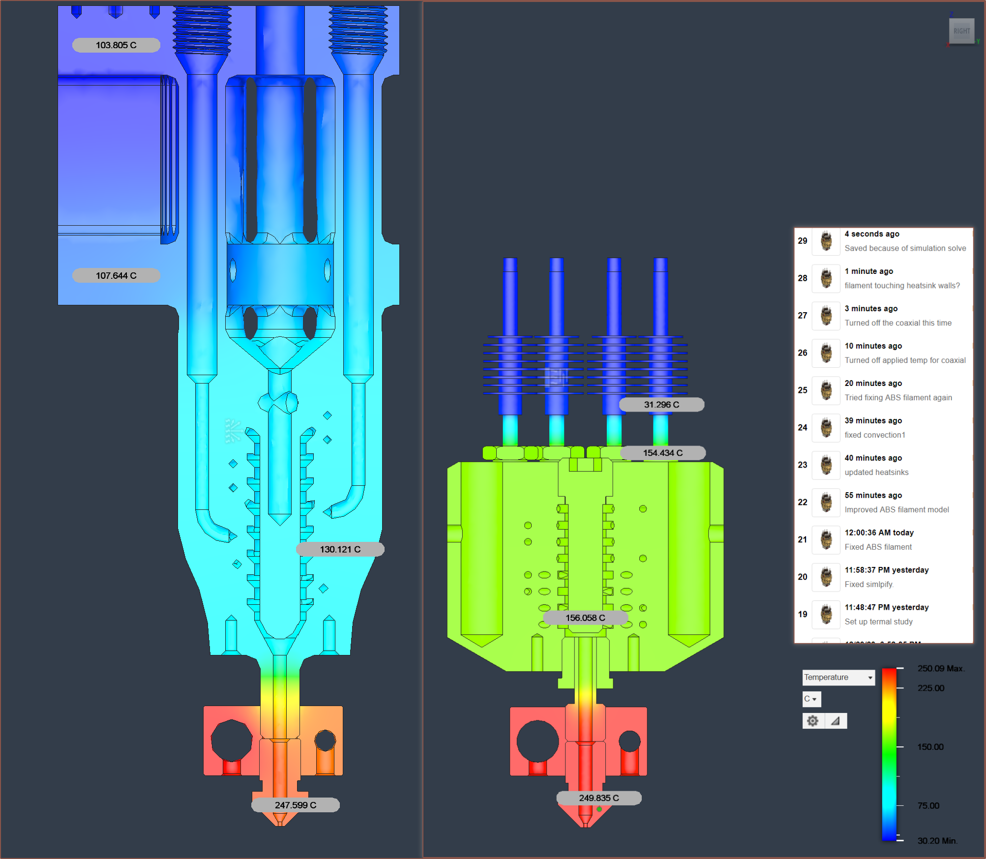
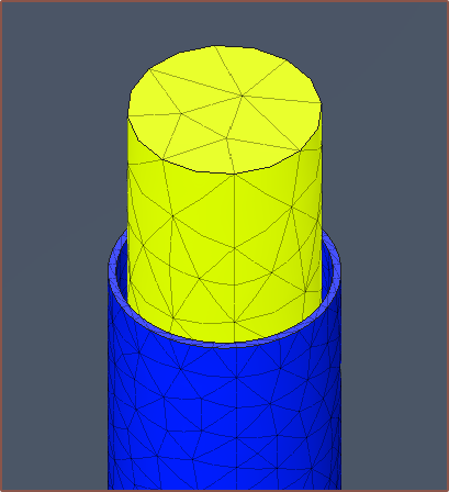
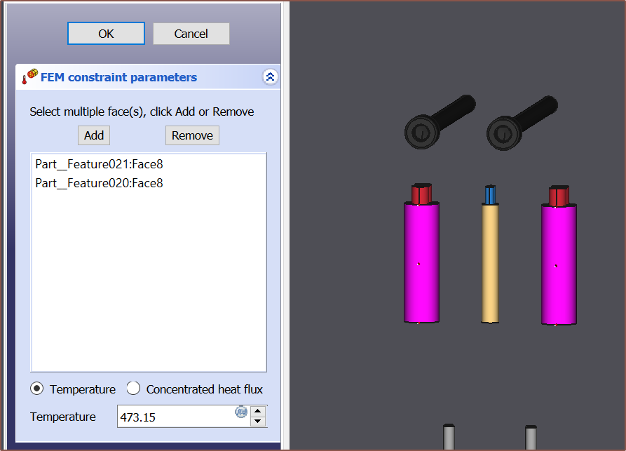
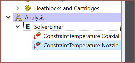
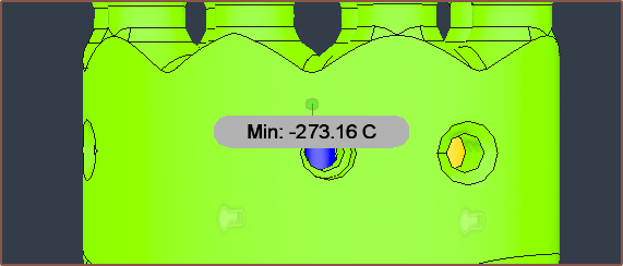
01/06/2024 at 01:49 • 0 commentsAs you can see by the save log on the right, it took a bit of effort to get the simulation of the machined coaxial hotend to generate believable results. I was having ABS filament that seemed to be uncooled, even though the contacts seemed to be set up correctly:
As you can see, the cooling performance difference is drastic.
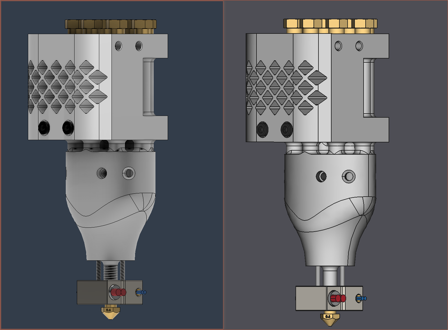
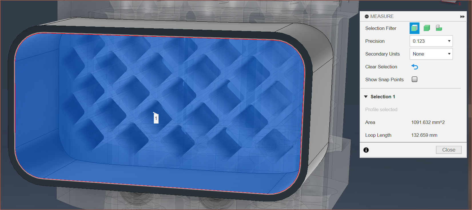
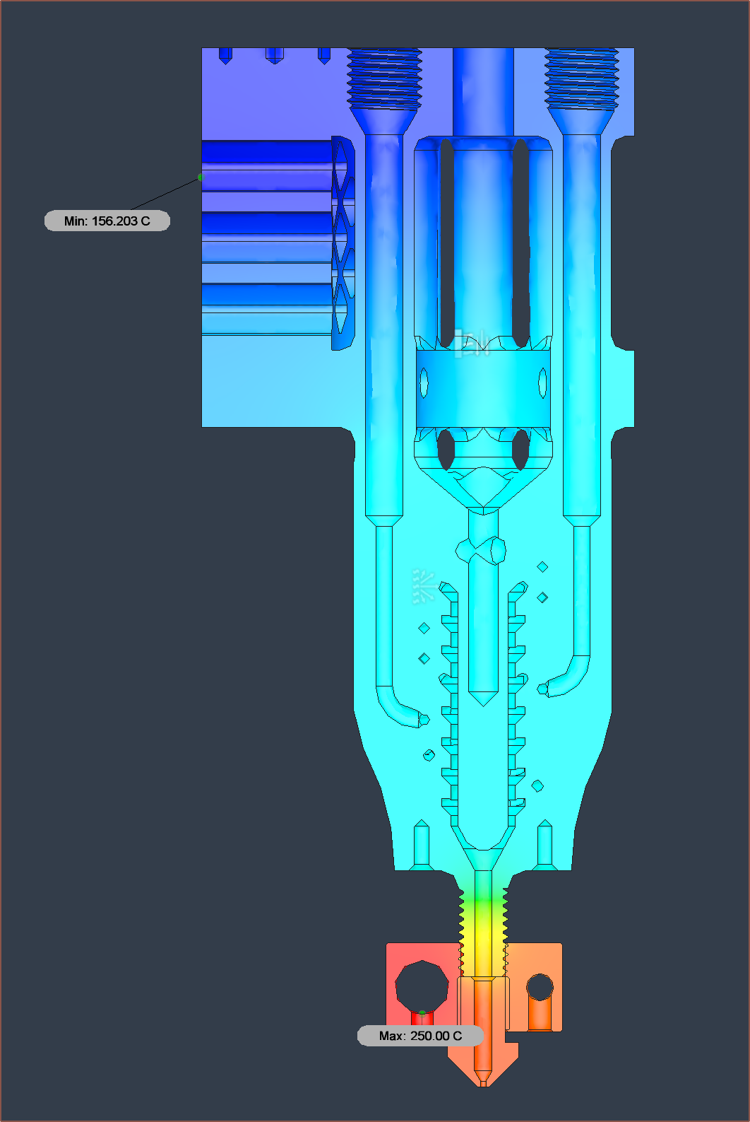
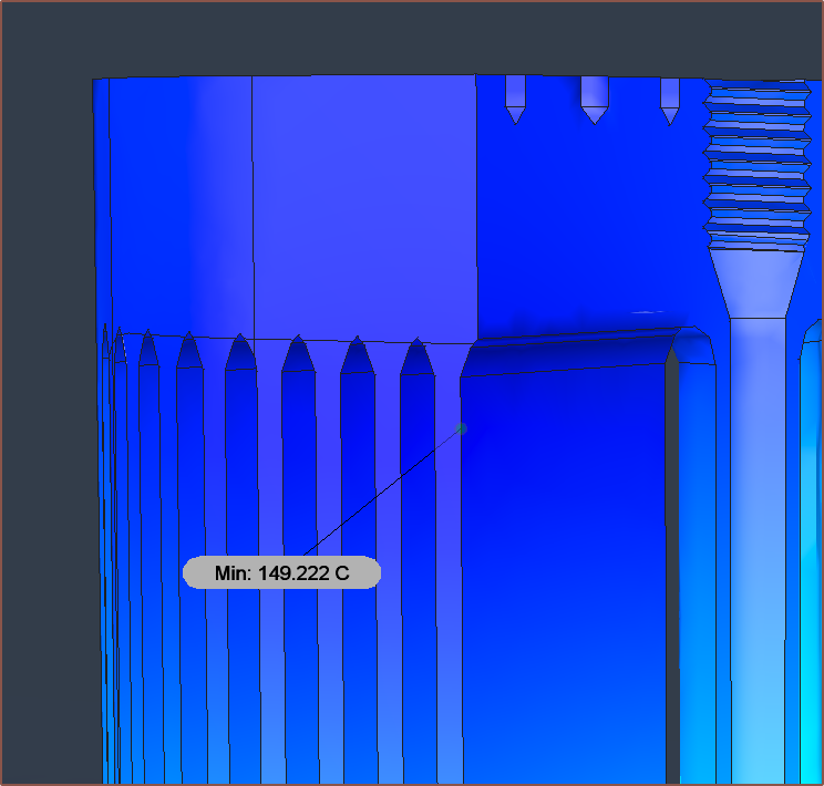
For the machined coaxial hotend, assuming that the 6028 blows over a CSA of 36mm x 15mm, I got a coefficient of convection to be 32.3W/(m^2 K) from a wind speed of 10m/s, implying that I could run the fan at half-speed and still have adequate cooling. I used 0.03 to be the emmisivity of radiation. However, the conduction through the heatbreaks in the unibody is much too high and thus the entire part is still over 100C.
Going from the simulation, it seems that for a nozzle temperature of 250C, the lowest I'd be able to run the coaxial block is 160C (which is also the temp at which PLA starts to melt). Additionally, not much heat is lost from the nozzle block, unlike the unibody hotend.
-
[E1][M][R] Simulation software and model optimisations
01/04/2024 at 06:49 • 0 commentsSo it started when I replied to a comment (that itself replies to me talking about this project):
Trying to set up a simulation
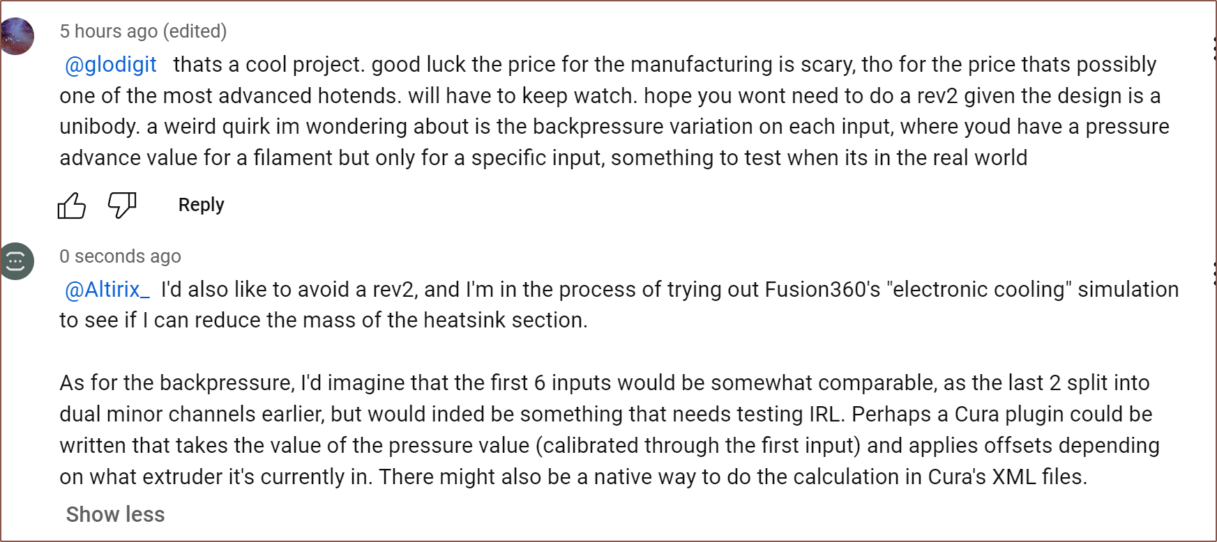
I was thinking that it would be as simple as setting up an electronic cooling simulation in Fusion360:
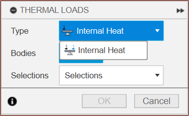
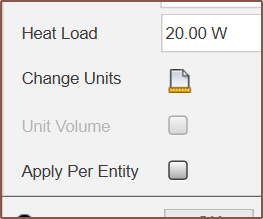
It only does internal heat? I assume that unticking "Apply Per Entity" means "Apply 20W across both bodies" Fusion360 suggested I added something. But then I go to solve and:
Thus, I started looking around for another solution.
Trimming down the mass of the hotend
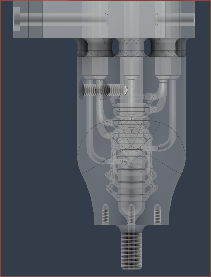
I realised that I could use a smaller elipse for the body of the hot section. I also tweaked the thermistor cartridge so that less of the hole depth needed to be tapped:
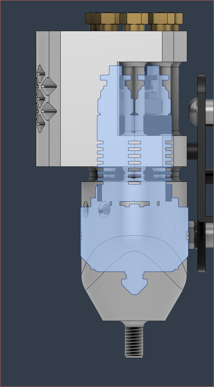
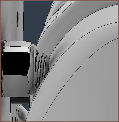
I extended the cut past the hole so that the M4 tap has space. This got the mass down to 220g. It also means that the bolt on the X-gantry no longer is a problem:Trying ElmerSolver in FreeCAD
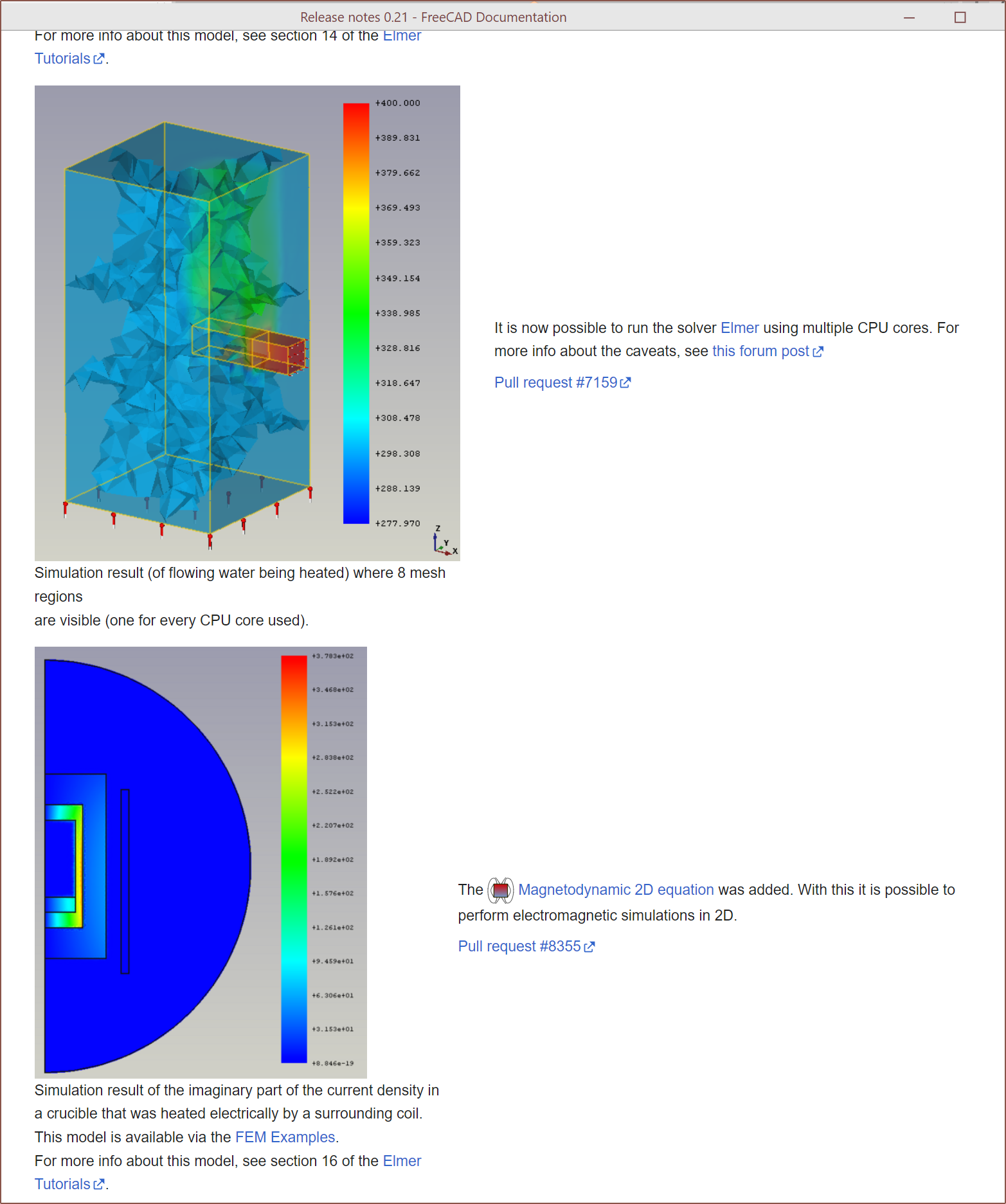
The main one I stumbled on was ElmerSolver in FreeCAD:
Me: Wait hold up. It does both thermals and magnetics? Where do I sign the download dotted line? I soon realised that Elmer was the software I was looking into for Tetrinsic too. Anyway, I imported the .step into FreeCAD and noticed that it looked slightly longer:
I decided to move on from that mildly interesting observation and start messing around with features until something exploded:
I just followed the wiki, such as downloading and installing the mpi version of Elmer. Since I was using FreeCAD, I assumed to download the nogui version. I was able to drag the constraints into the solver, so I assume that's what I'm supposed to do. I gave up around about here when I got tired of having to select each face manually and couldn't (get BingChat to) figure out how to select all faces through the python console. Looking for other solutions
- There's Simscale but it seems that the free teir only gets 10 solves and there was no mention that they reset after a certain amount of time.
- There's OpenFOAM and I'll have to look into that, since FreeCAD supports that too.
- There is Simflow that is based on OpenFOAM that seems to have a very nice-sounding free tier
Further design optimisations
I asked Elelven about any price reduction strategies and she, once again, suggested to skip on the tapped threads:
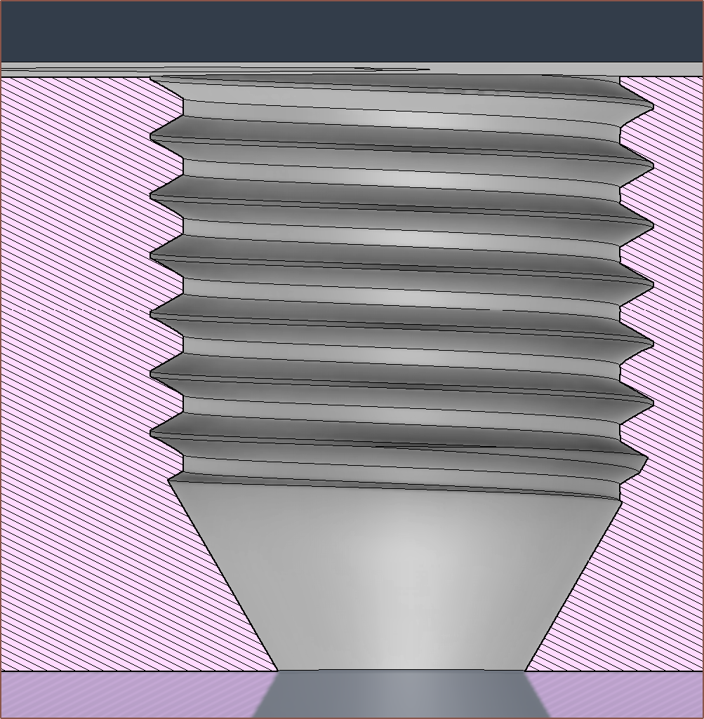
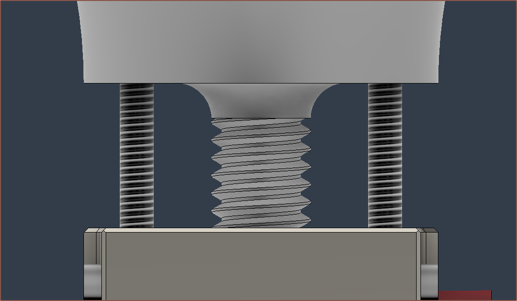
I thought that it would be a good idea to actually modell the important threads into the part, which are all the M8x1 threads and the M6x1 thread at the bottom. I watched the first strategy in the below video and looked at comments, and decided to offset the faces by the equations below the video.
tol = 0.3mm
Angled Faces Offset:   -tol / 4
Vertical Faces Offset: -tol / 2
Lastly, I deleted the bottom-most face so that there wouldn't be a 90 degree overhang where the thread meets the internal chamfer:
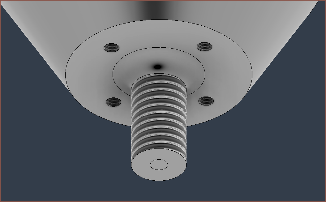
Then I did the M6:
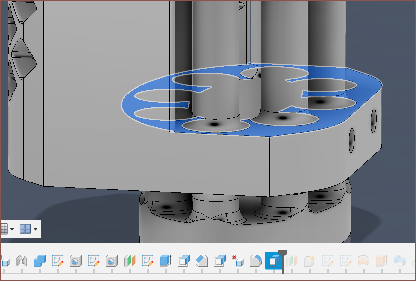
The next thing to do was to remove the flat face that would require the printer to bridge 90-degree overhangs and replace them with 50 degree overhangs. To get the starting chamfer to work, I first had to offset the eliptical face:
Then I could do some more DeleteFaces magic to obtain this:
Lastly, I pushed the below face down to save around another 3 grams. The result is that the autoquote is now $167.17, over $20 lower than the first version I sent to PCBway.
The end result looks a bit more interesting now:
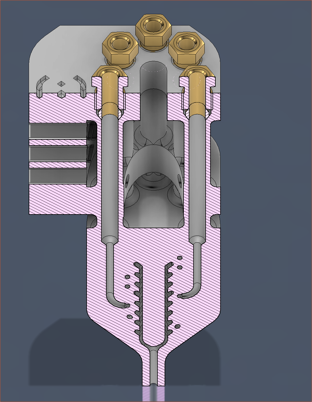
The bounding box (compression fittings to nozzle tip) is 49 x 49 x 124mm and the printed mass is 212g (down from 241g from the first version I sent to PCBway), which is in the same ballpark as 10W+ (output) laser diode module sizes. Unfortunately, it seems this hotend is going to be in the same ballpark in terms of price too.
[08:40] I just got the price and it's a whole $194.00, so the additional cost for tapped threads is likely the similar $30-ish that I experienced back when I designed and submitted the printed coaxial heatblock.
[20:40] I also looked at the additional fees involved. Fedex is suprisingly the cheapest option, even lower than others like China Post or PostNL. At an optimistic best, the entire cost is £182, but could be as much as £182 + 20% duty + £12 Fedex fee = £230.
[Jan 05] I found the issue with Fusion360; I needed to change the cloud credic preferences.
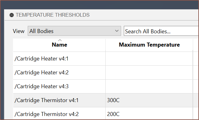
I then proceeded to try and set up a thermal study, trying to get over the hurdles along the way:
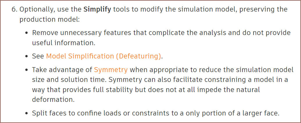
This was the most common issue. I followed the suggestion of symmetry, as per the Fusion360 docs:Then alculated the convection coefficient:
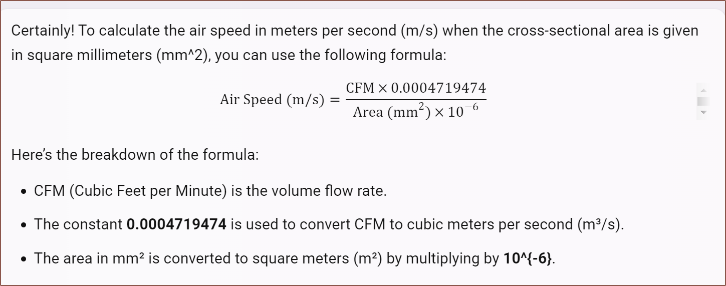
(11.89 * 0.0004719474) / (1092 * 10 ^ -6) = 5.1386946758 m/s
10.45 - 5.13 + 10*sqrt(5.13) = 27.96950330581225 W/m^2-K
And this is the result for a nozzle-cartridge temperature of 250C and coaxial-cartridge temperature of 180C:
As you can see, the heatsink is mostly ineffective.
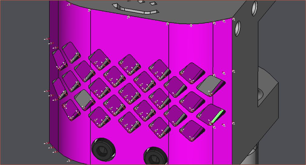
I tried a fin-based design and it slightly improved things, but still nowhere near good enough. It seems that "it's over.", with the only mitigation strategy I can think of being to reduce the amount of material that makes up the vertical tubes by modelling a mesh design.
-
[T] Abrasive filament to smooth internal channels?
01/01/2024 at 23:47 • 0 commentsSo I saw this video of Construct3D's experimental 6-in-1-out hotend that aims to get 200 cu mm^3 per second:
They got the part tested to see how much the actual part deviated from the CAD file, and they were "only 50 microns out in some places". One of the issues that they want to look into solving is the surface texture. 2 commentors I saw suggested "extrusion honing", which puts abrasive paste through a pressurised channel to smoothen the walls.
This suggests that something similar could be done with abrasive filament. I believe glow-in-the-dark is one of the more abrasive filaments commercially available whilst also being relatively affordable.
-
[E1][M] Finished modelling the Unibody 8-in-1-out hotend
01/01/2024 at 06:20 • 0 commentsI like how the general design is perfectly themed to my logo. There's not many logos that can do that. Only the PearPhone (Victorious / iCarly) comes to mind. So this took 6 hours to do. A long time, yes, but something I wanted to get done since the start of October. At least it's a nice way to start off the year of 2024.
First, I had to figure out how I was actually going to join up the internal channels, and was thinking of things like this:
Then I said "Why am I making things difficult for myself?" and just did this:
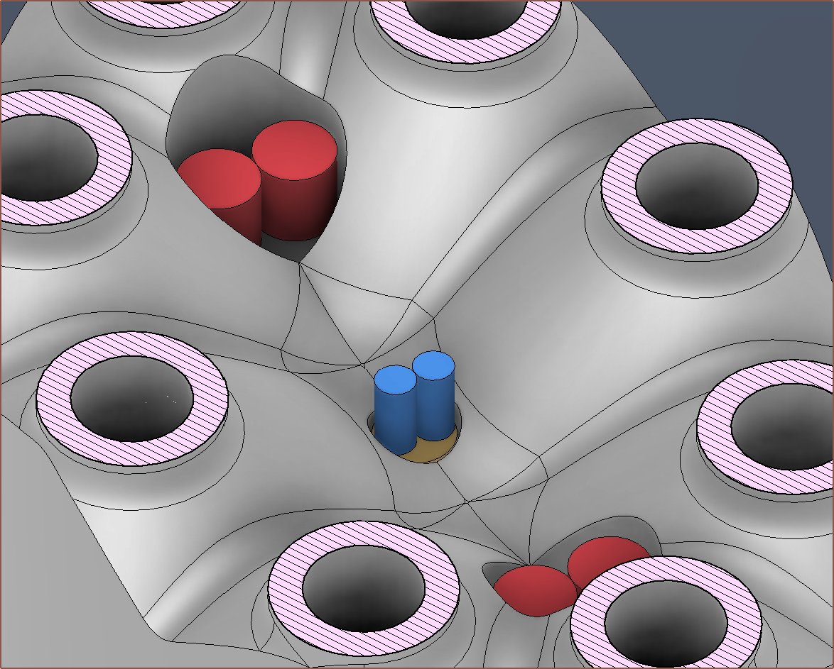
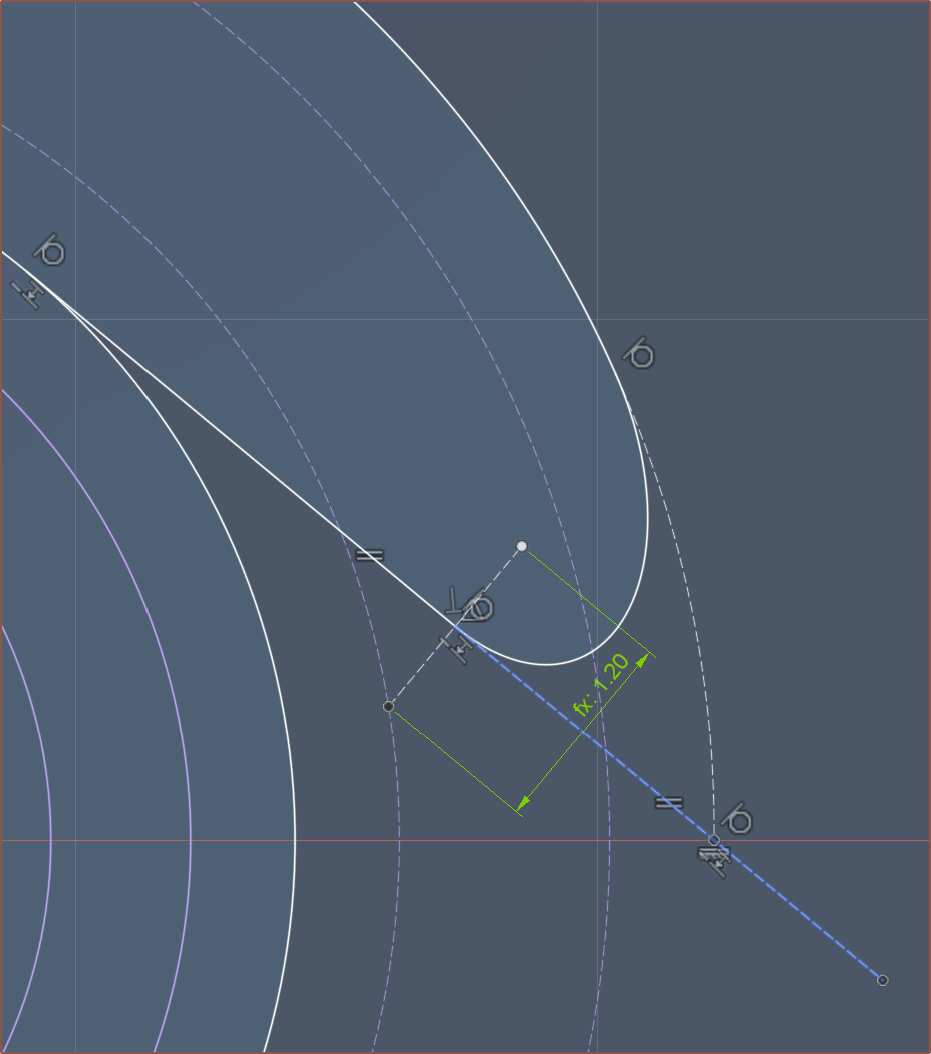
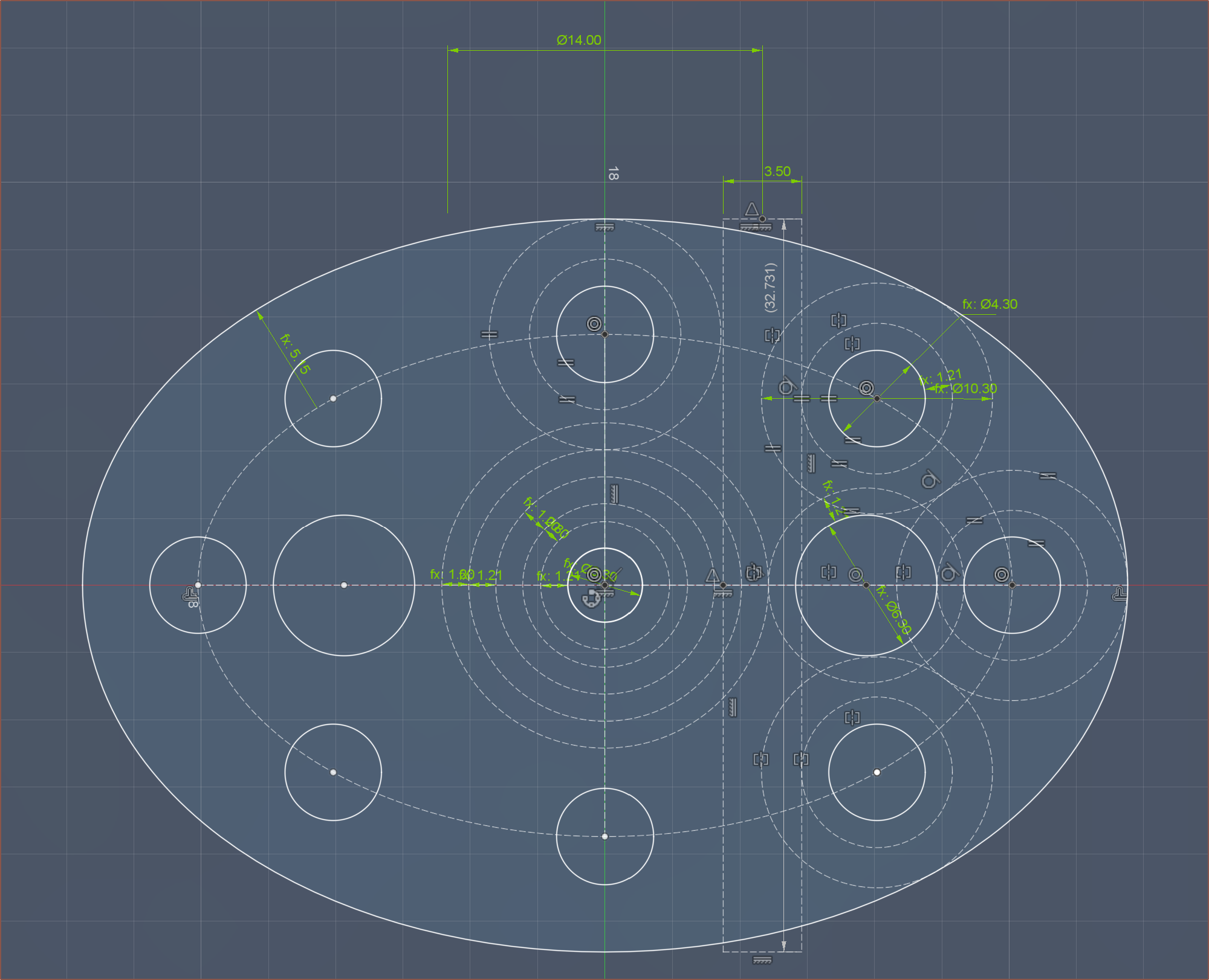
Next, I took advantage of the new Fusion360 feature to use driven dimensions anywhere in the file to make sure all of these 8 bodies were seperated by at least 1.2mm:
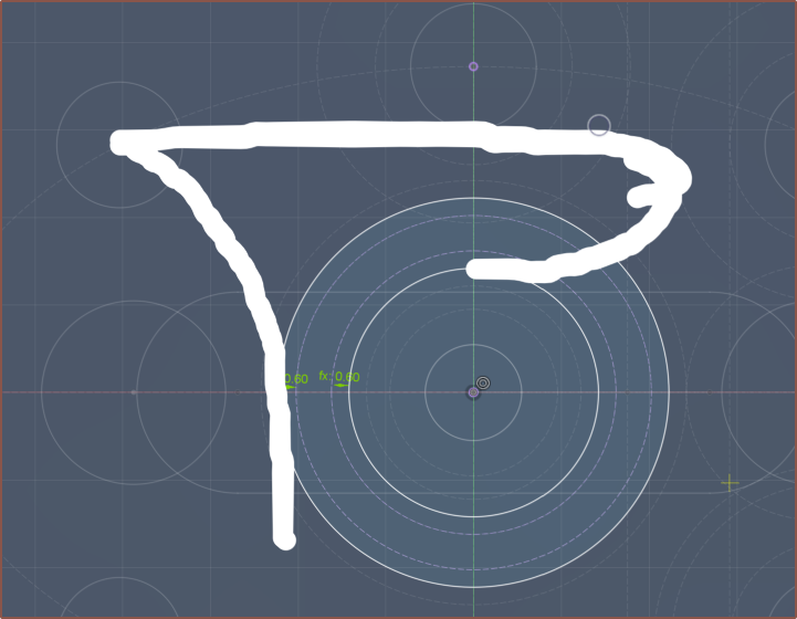
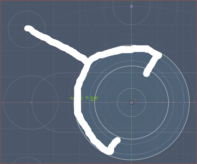
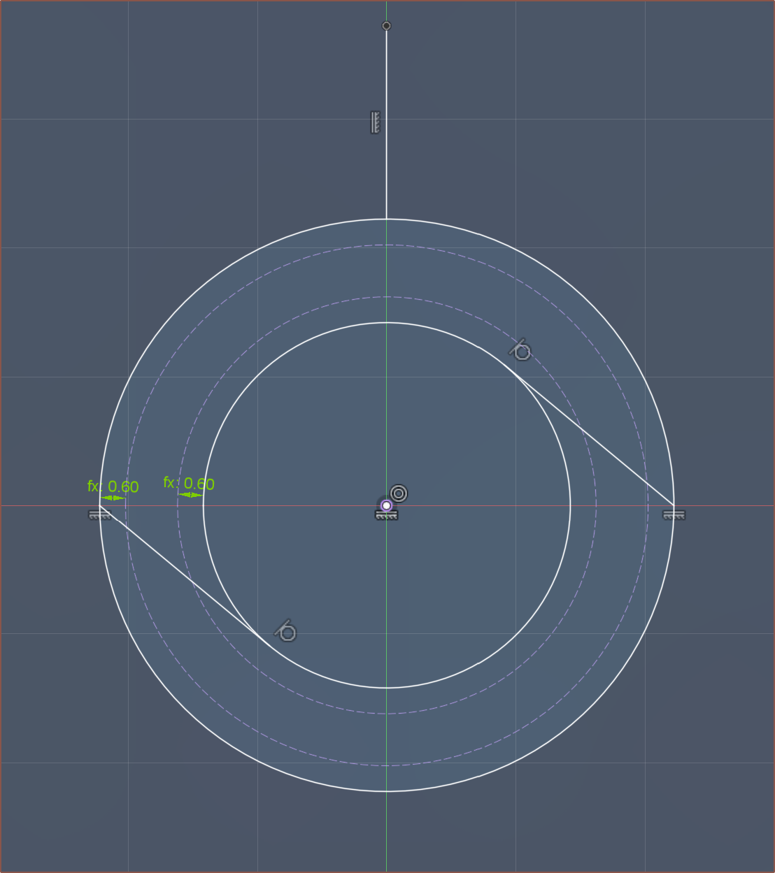
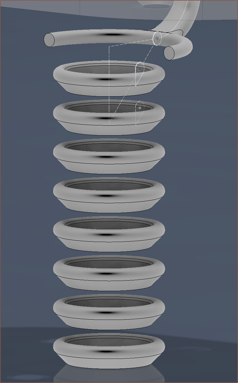
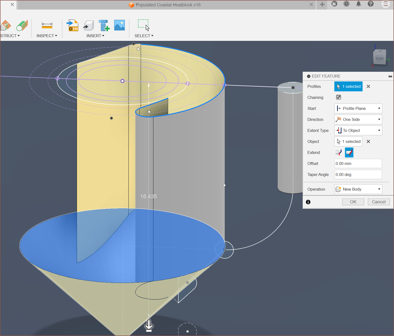
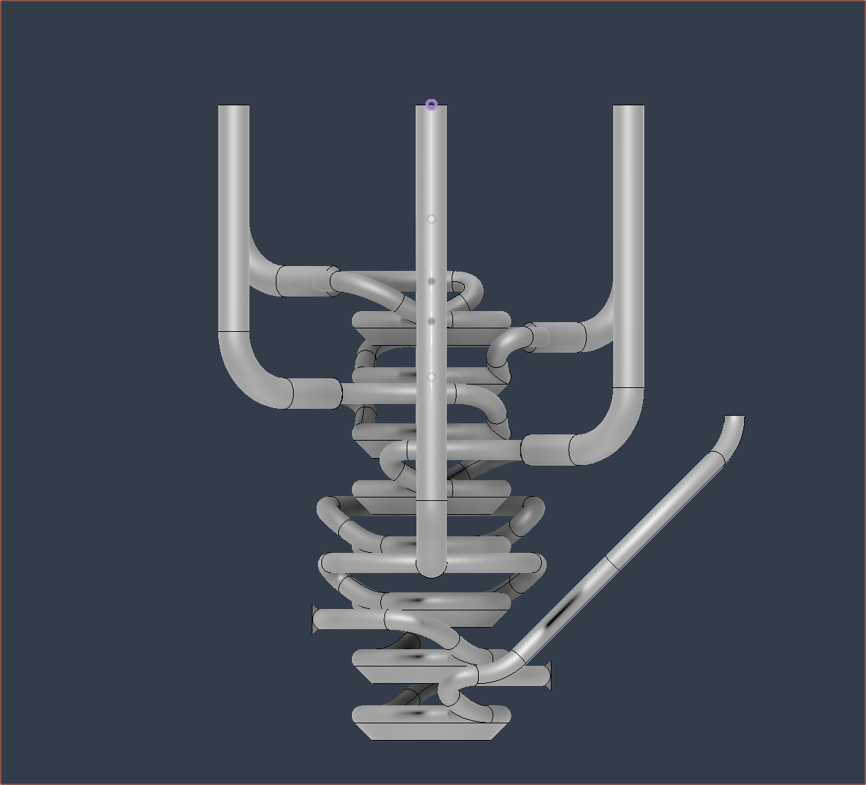
Next, I did the main thing I've been planning to do for weeks, which is a cone-derived path:
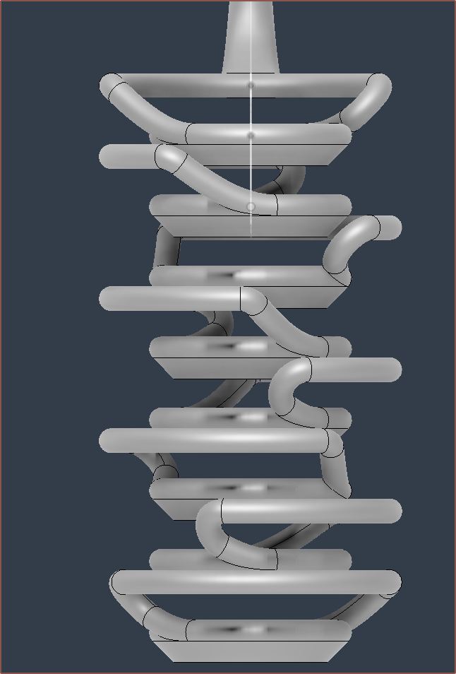
I decided to just have all of them going counterclockwise. Suprisingly, it actually worked. If you're wondering why I've done this, it's so that there are no internal overhangs to keep print surface quality optimal. Since everything seemed as expected, I went back and replaced the arc with a "conic curve" so that a better 3D bend could be generated:
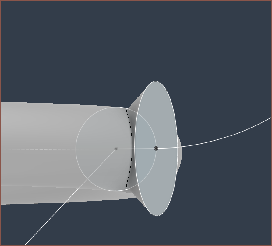
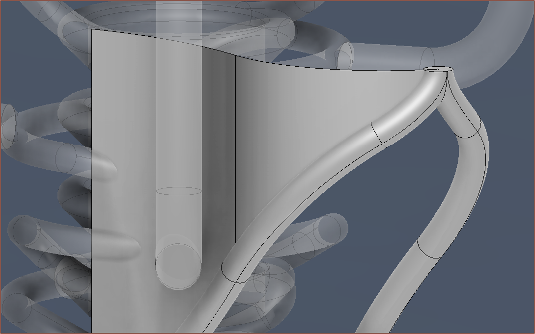
The resultant 3D curve is also much shallower a bend than if I had tried to keep this kind of acute turn in the same 2D plane. After that, I added some ports for the "MajorChannels" to tap into:
I kept on adding channels and then I got to the side-most ones and I was so close yet so far:
I need to maintain a wall thickness of 1.2mm, and this channel was 0.5mm away from the vertical one. The solution? I reordered them. I believe it's better now as it's the optimal order for me to model in a large 45 chamfer and allows the filaments on the surface of the extrusion to be thoroughly melted.
I used the magic of "Delete Faces" to cutt off the excess. Now it was time to combine cut the internal channels from the main body, and it looked good in the Section View:
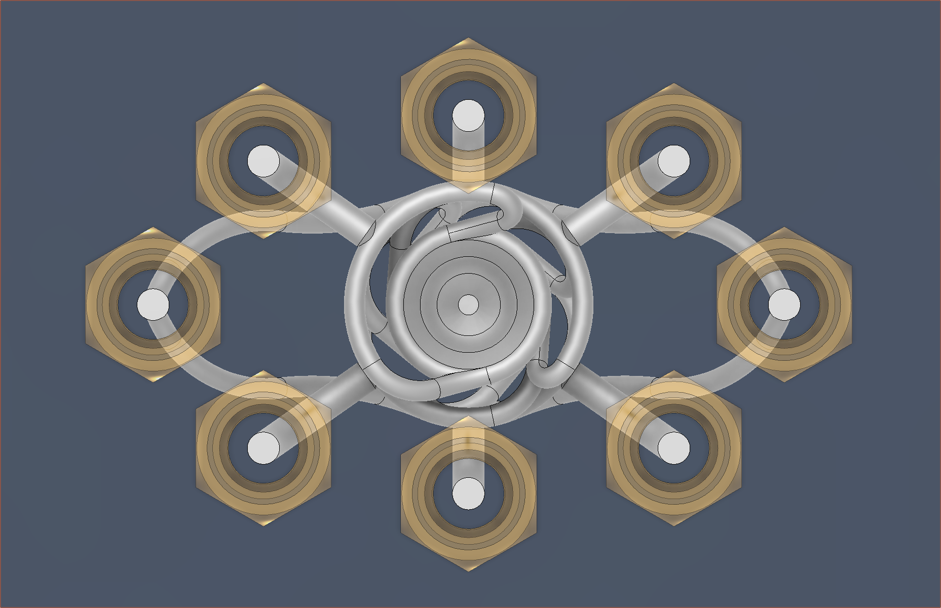
It also looks cool from this top-view:
Then remembered that I need the M2 threads so that I can still do 1-handed nozzle changes:
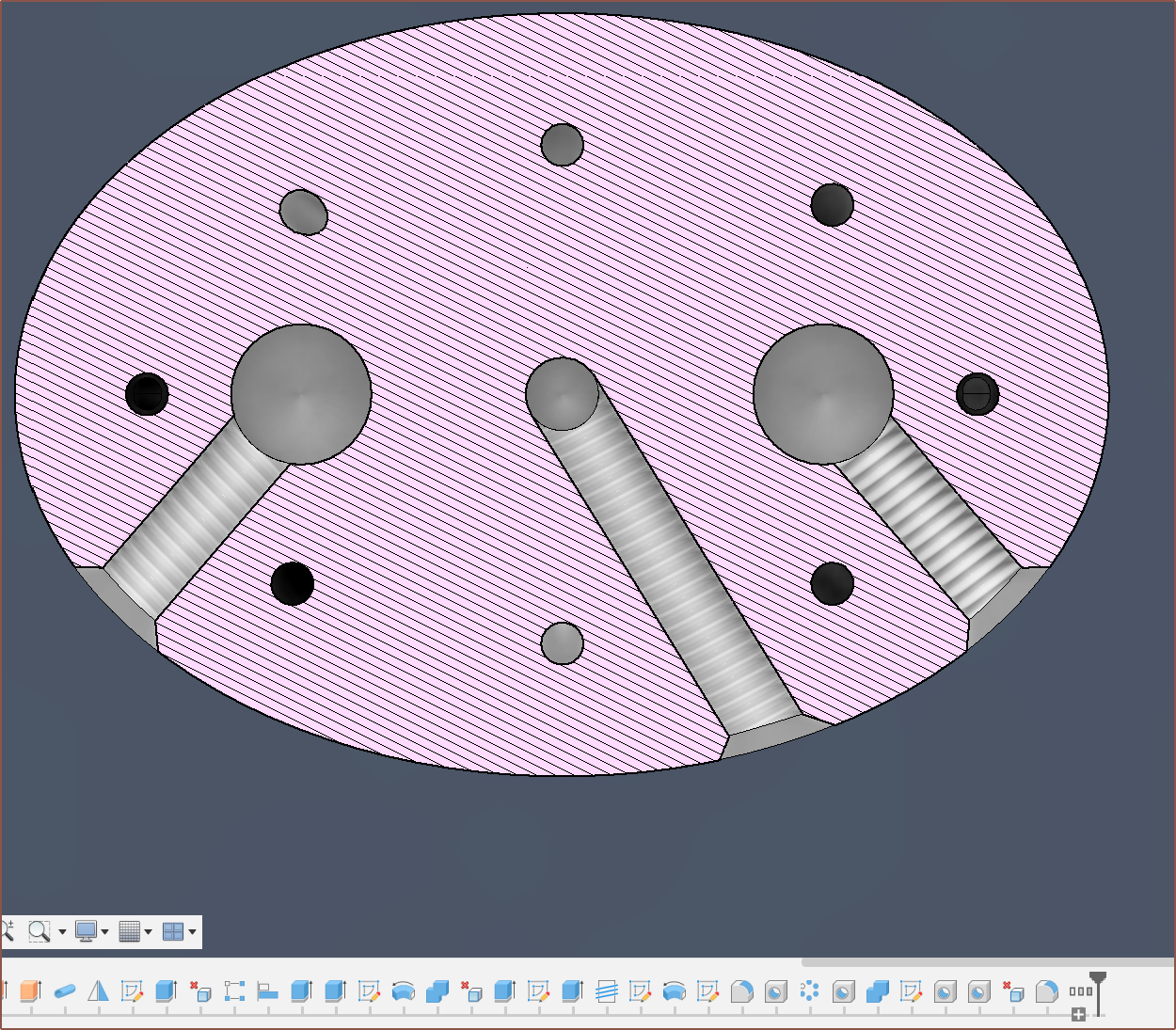
Added the cartridge holes and thread holes, making sure that the thread paths were equidistance from the input channels:
So the design was mostly done and I decided to import it into the larger assembly to compare:
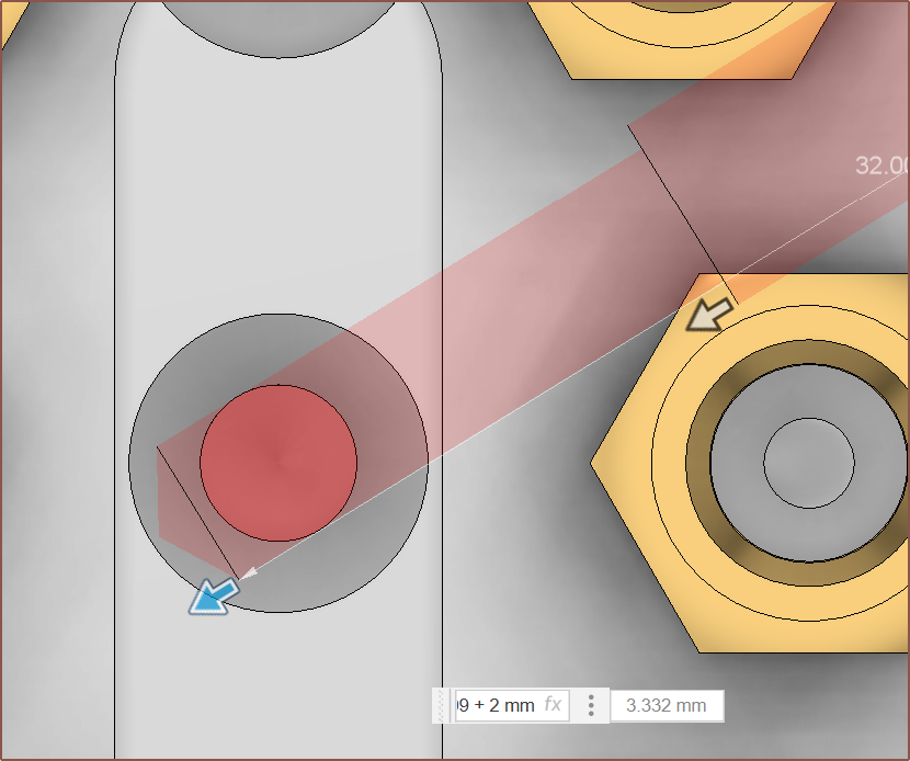
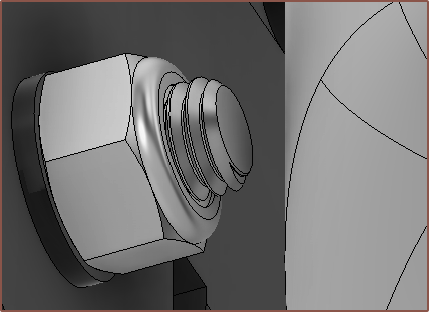
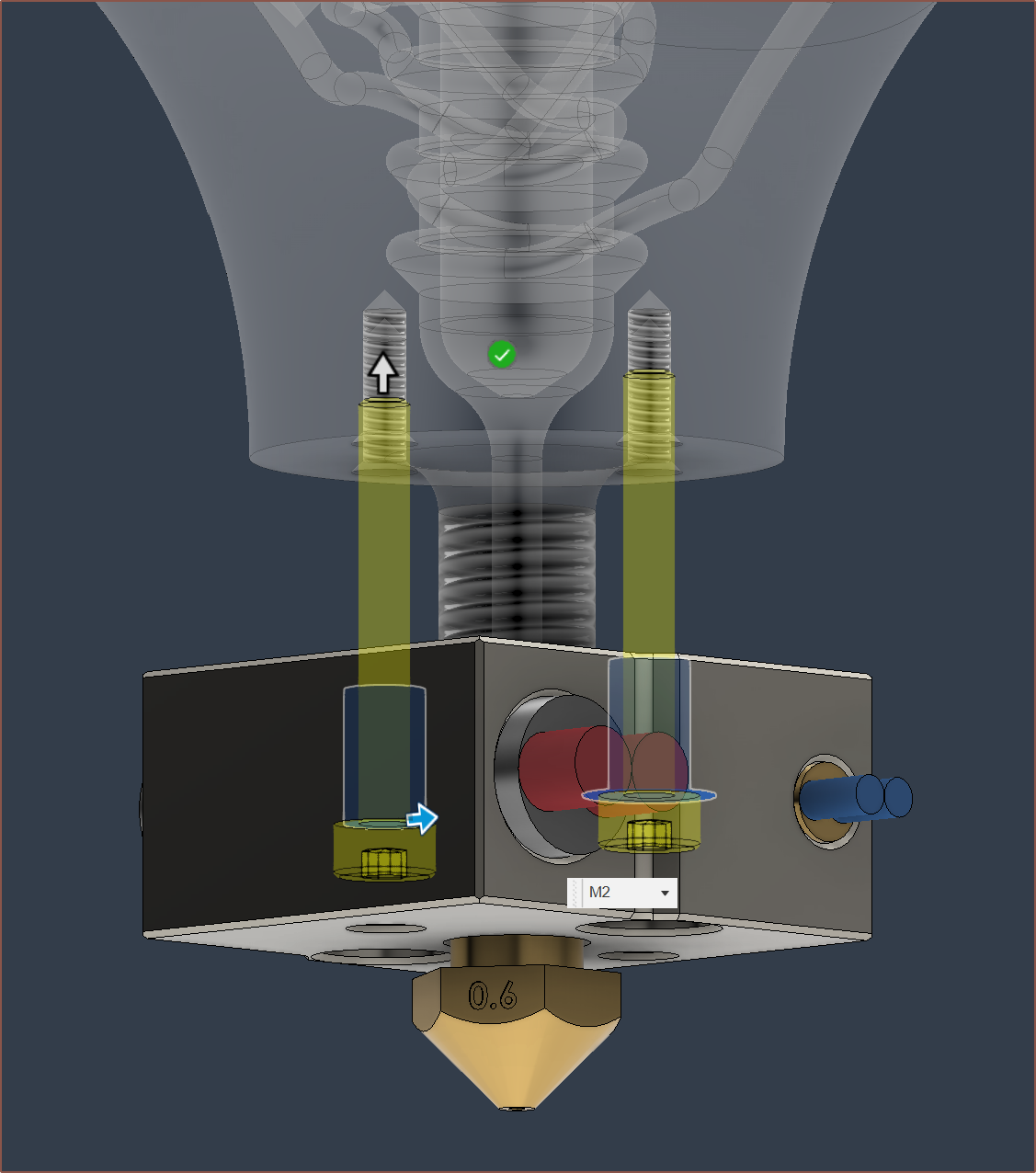
Not too bad considering it has to handle double the inputs. I've got to do something about this bolt. I'm not about to start changing the model to avoid this thing. I tried the brand new to Fusion360 feature which brings in fasteners. Allegedly, having to Partpicker everything will be a thing of the past:
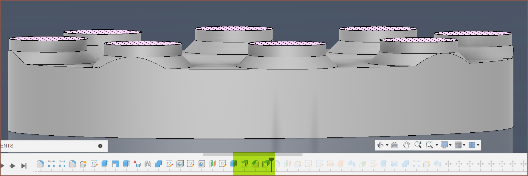
However, I'm not so keen on the timeline noise (see below) nor the fact that only things that are in the active component can be fastened (though this is mitigated for the most part as all fasteners go into their own folder).
Lastly, I added some M4 threads so that other things, such as the 3D printed cover holding the fans, can be mounted:
Before today, I worried that the thermistor wouldn't be able to get an accurate reading of the cartridges due to a layer of molten plastic inbetween, but I think there's plenty of direct-metal between the two:
And there you have it:
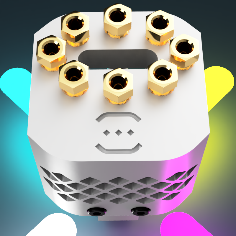
This hotend has been designed specifically to be mounted onto CR-10 / Ender3 esque gantries (like the TronXY X5), as the M3 by 14mm spacing seems to be quite popular these days. Fusion360 says that all of this is 392g. The brass compression fittings on the top contribute 100g alone. The machined model, without these fittings, was 306g, so the mass is comparable between them.
Now to see how much it costs...
*VERY AUDIABLE INTERNAL GHASP* At that price, I'm not risking a bent thread. I'll as for that too:
[2 Jan] That increases the price by another $46 and the build time by 6 days:
It's certainly more expensive than I would've liked, but many other strategies for multicolour/multimaterial are around about the same ballpark or higher. I was hoping for sub £100 ideally, but the mass of this hotend was also more than expected.
-
[M] Heatsink for Unibody Coaxial Hotend
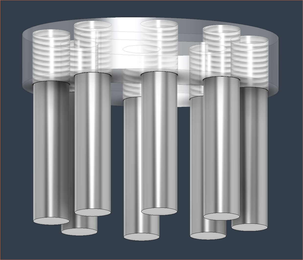
12/30/2023 at 06:36 • 0 commentsFront Back So I've been thinking of how I was going to do this for a while, such as the geometry and feature order. The first thing I did was research how heatsinks have been designed by others, and what I could gather is that they a) make sure that it's printable geometry, b) they usually use lattices and c) add fillets to prevent sharp edges.
Part a sounds obvious, but it means that I'm unlikely to be able to use a standard hotend design (see below) considering that I intend for PCBway to print upside-down.
Just like with an FDM printer, those overhangs wouldn't print. If anything, DMLS is even less tolerant of overhangs than FDM.
But other than that limitation, it doesn't seem like there's any general best-practice for this kind of thing short of CFD so I had to come up with my own solution. Well, I finally looked into designing something after days occasionally thinking about it and the idea I had come up with was reduced to atoms when I got here:
Turns out that these tubes for the PTFE are so wide that the idea I had would mean that there would be almost no fin surface area.
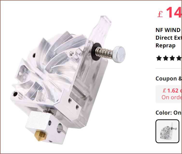
The solution? Designing the heatsink infront of the tubes, similar to the metal part of this BMG extruder:
For the most part, if I remember correctly, air goes around cylinders relatively uninterrupted, so hopefully the airflow is decent.
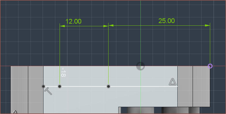
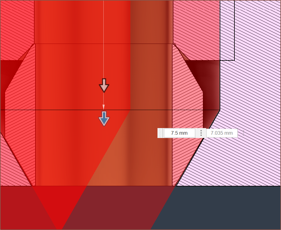
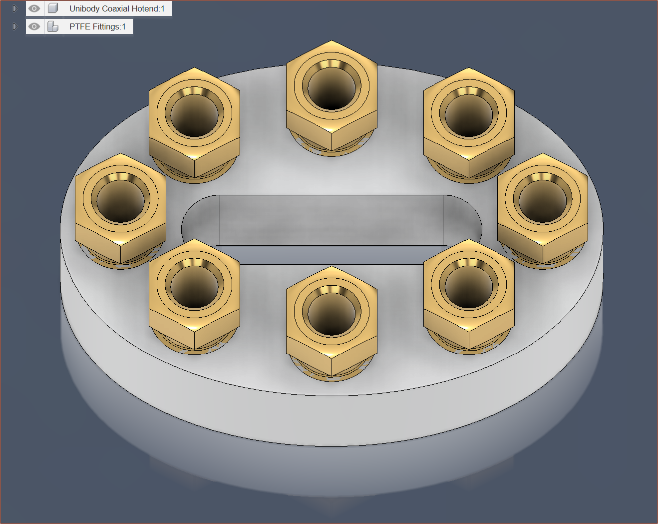
For the PTFE compression fittings, I've used the Fusion360 hole feature, with a bottom angle of 60 degrees, thread depth of 6.5mm, total depth of 7.5mm and thread of 8x1.
I also increased the walls around the threads to follow this recommendation:
-
[T] Print abrasive filament without abrasion?
12/19/2023 at 13:55 • 0 commentsSo I've finally had some non-allocated time and I've used it to research what's new/changed recently. There's a high viscousity, open material jetting 3D printer called NovaJet OPEN now, the Cetus2's near-instant changing, mulitcolour hotend is now on AliExpress for like £100 incl shipping, LulzBot actually came out with a new printer with an approx 28cm * 58cm * 28cm build volume (which I don't know if it's going to survive with a $8K asking price) and I was scrolling through Raise3D's new RMF500 industrial printer website and saw this:
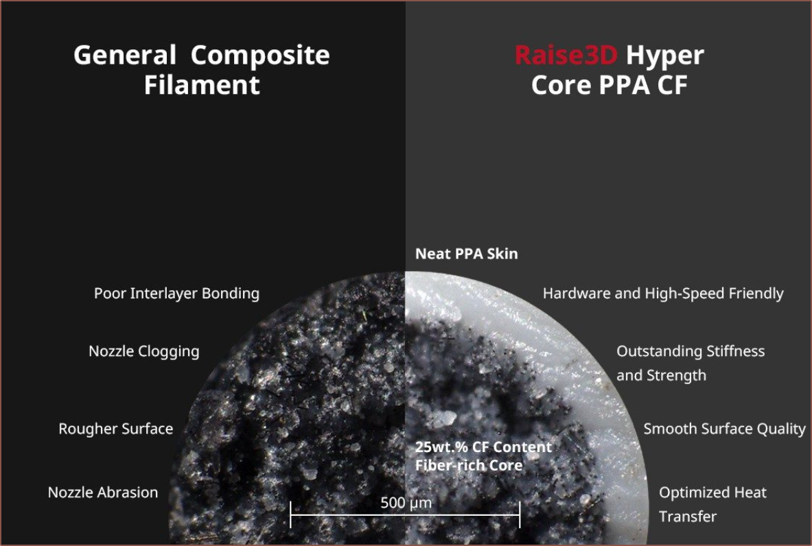
Something I didn't quite realise when thinking of the coaxial capabilities is that abrasion of the nozzle should only happen at the surface of the filament material, and if that material is encased in a non-abrasive material like transparent TPU, hypothetically I could be printing in carbon fibre (CF) and glow filament with a standard brass nozzle. Raise3D also lists poor interlayer bonding as a drawback to composite filaments, adding a bit of credibility to my idea of having the outermost material be a "glue" material.
In other news, the last time I worked on the Coaxial Hotend was November 20th and this is where I left off:
-
[R] Bowden couplings, collets and compression fittings
10/25/2023 at 18:07 • 0 commentsSo I've had the main sketch ready to go for a few days now, which has unexpectedly become an eliptical shape when trying to minimise the size whilst still taking constraints into account. The main constraint is that I want this hotend to be able to mount directly to printers that use 2x M3 bolts spaced 14mm apart and popularized by Creality.
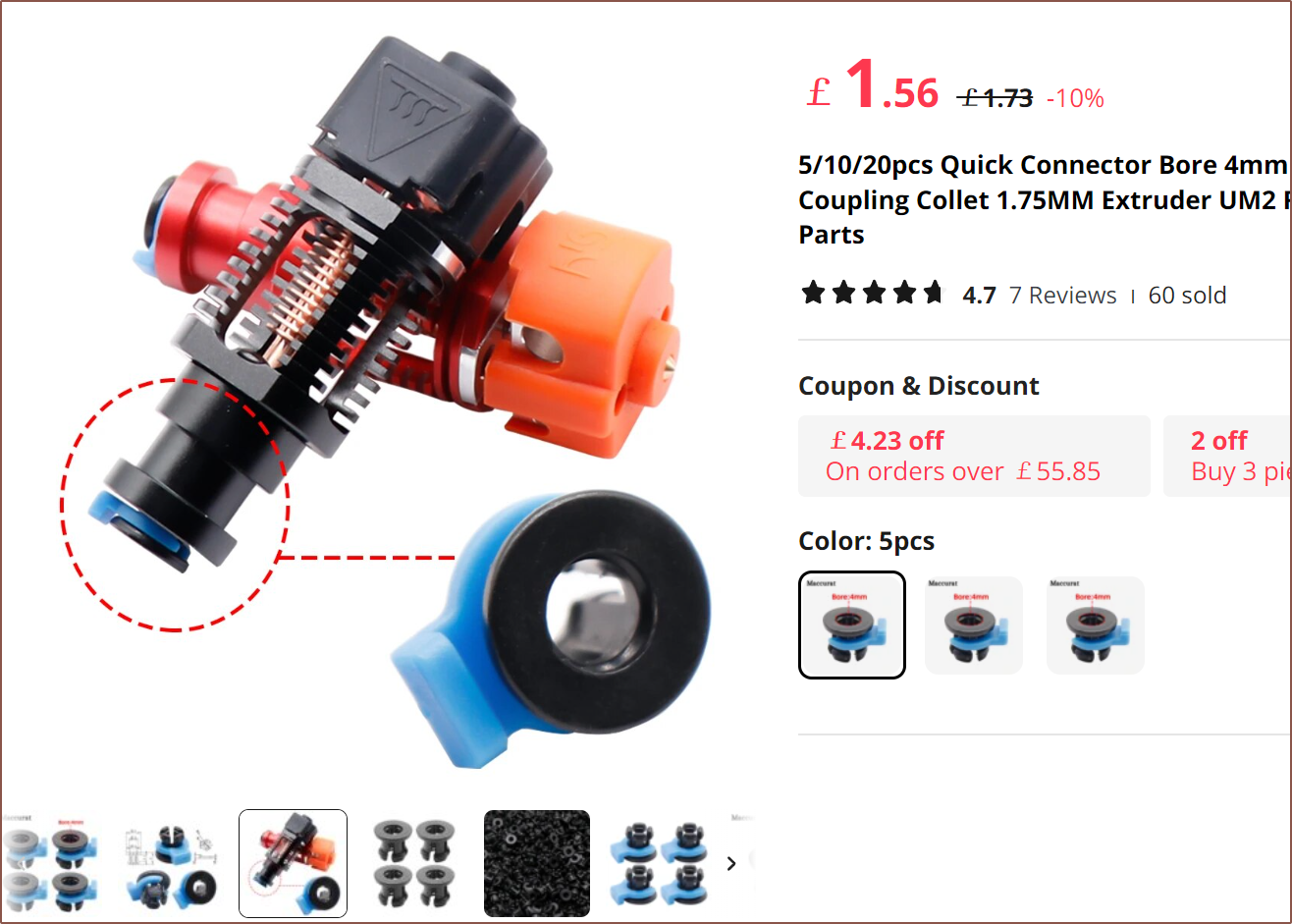
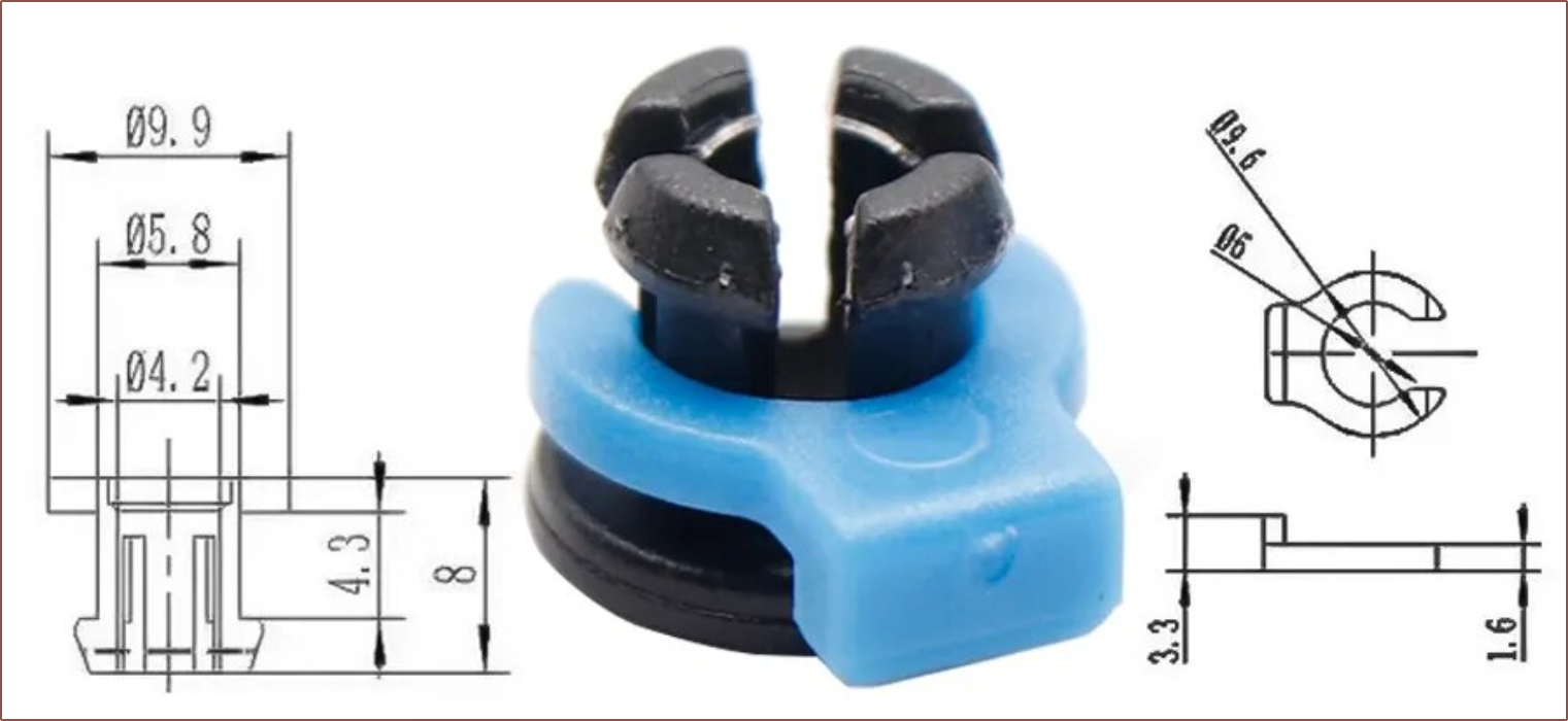
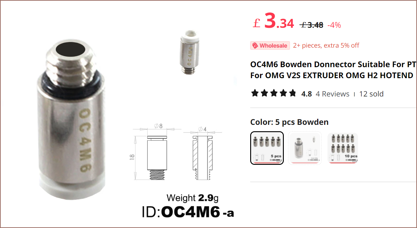
Now, other than that mounting constraint and the constraint from PCBWay that recommends that walls are at least 1.2mm, the method of holding the bowden tube in place dictates how compact I can make the unibody coaxial hotend. Until I looked into it further, I was planning to use something I believe are called "bowden collets":
I tried and failed to find out what internal geometry I should use on for the metal print, but looking at the drawings of the collet and plastic clip, I was thinking that I could model a good guess.
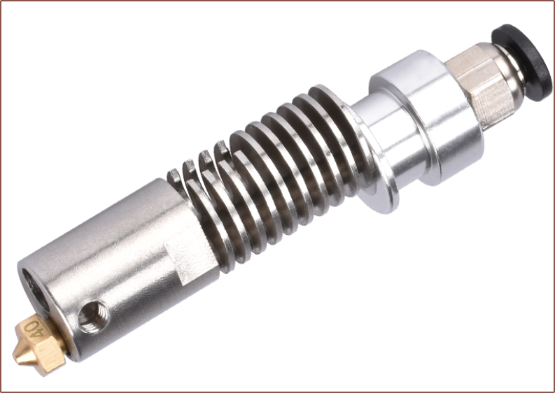
The thing was that I was also considering this coupling as it only has a max diameter of 8mm instead of 10mm for the collet:
Unsure, I started researching since the bowden holder determines how large or small the hotend can be. I then found this video:
This is when I remembered all the ways a print could have reduced quality or fail because of something to do with the bowden tube. It's already bad enough with 1 input, but my decimal odds of a problem are much higher when there's 8 inputs that all need to work together. I looked onto Reddit and the comments in this post seem to echo that a compression fitting is the best option for this application.
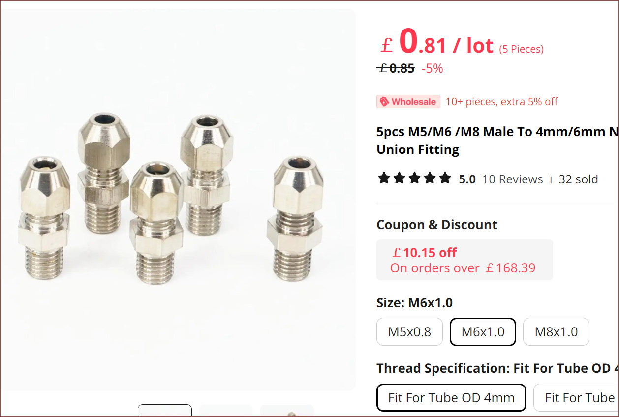
The first potential option I found was this:
Looking at the below video, it seems that there is a version that uses 1/8 BSP threads that are usually used with Creality heatsinks, and the hex doesn't look like it passes over the edge of the heatblock so I can probably assume that a spacing of 12mm between inputs would be required for this fitting. Additionally, some light drilling is required to allow the PTFE to pass through the fitting.
Now that still sounds like there could be a more efficient way in there -- one that doesn't require drilling and screwing the threaded part and then screwing another part ontop, and perhaps requires less spacing between input channels.
Such a solution actually may exist.
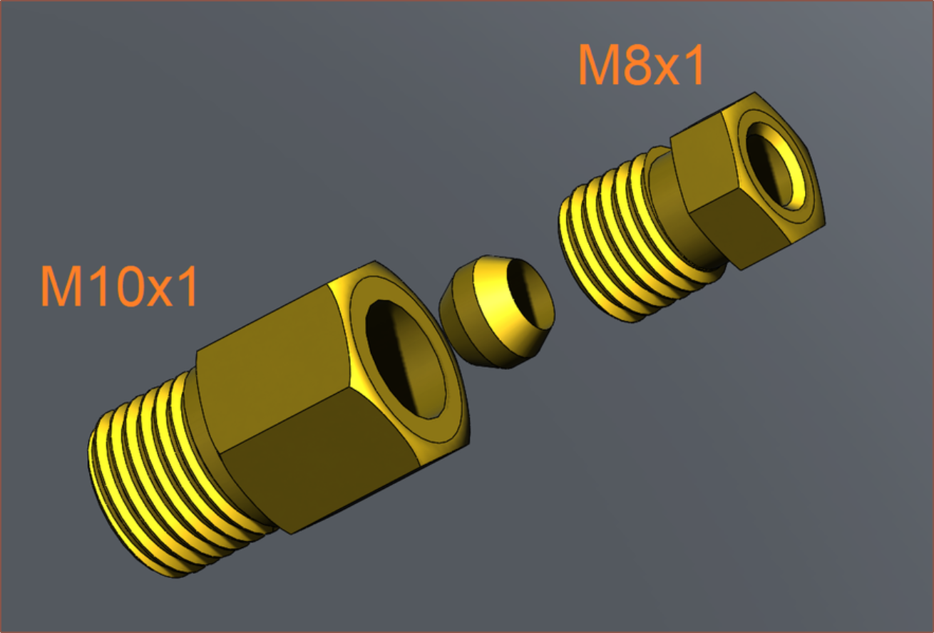
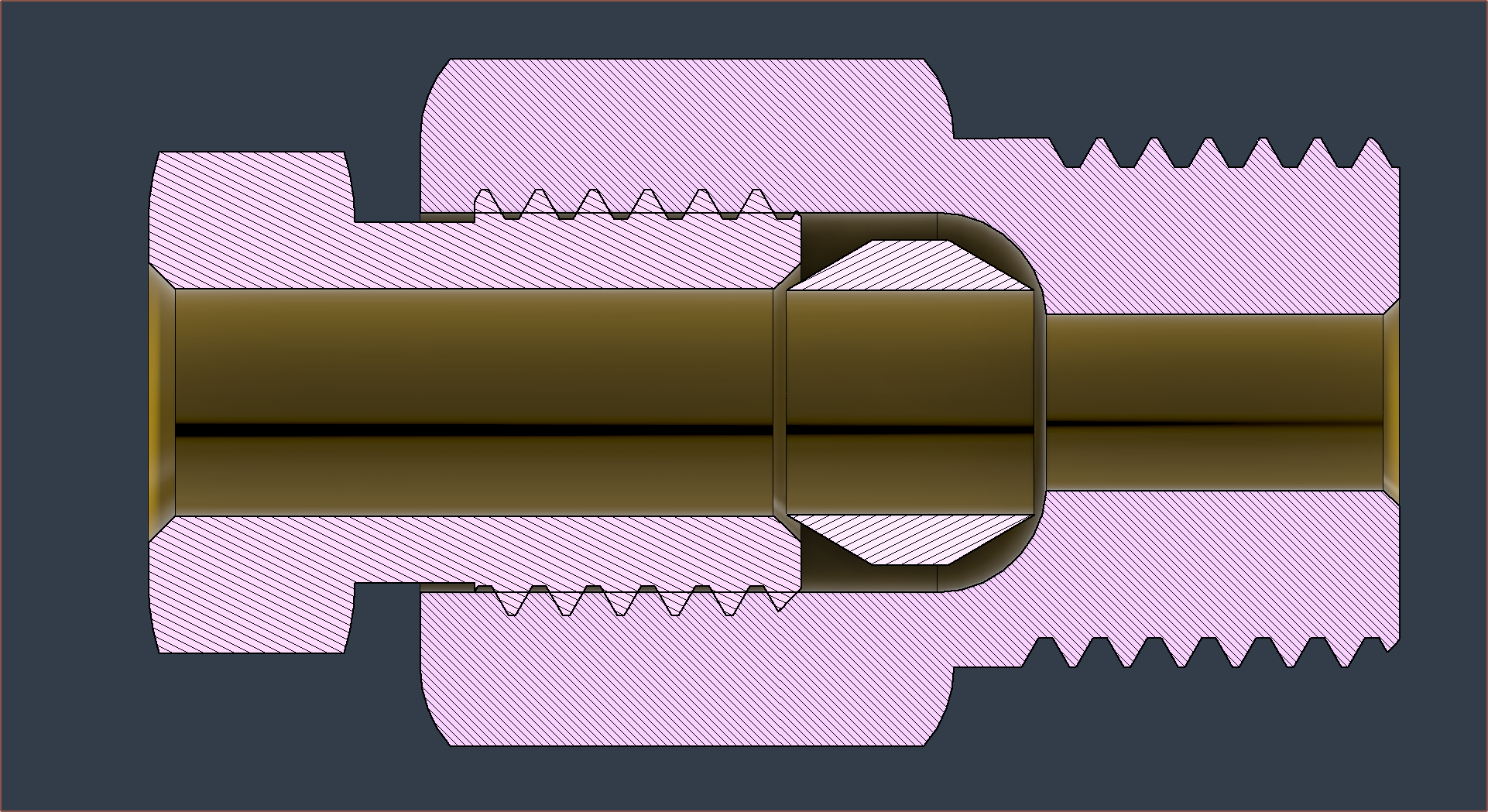
I found this fitting and then was able to find a very similar 3D model on GrabCAD (click the image to go to the source):
This allowed me to be able to see inside. I lowkey pine for the day when AliExpress, some day in the future, is some VR digital marketplace and most products have 3D models instead of today's task of looking at 2D images and hoping for the best.
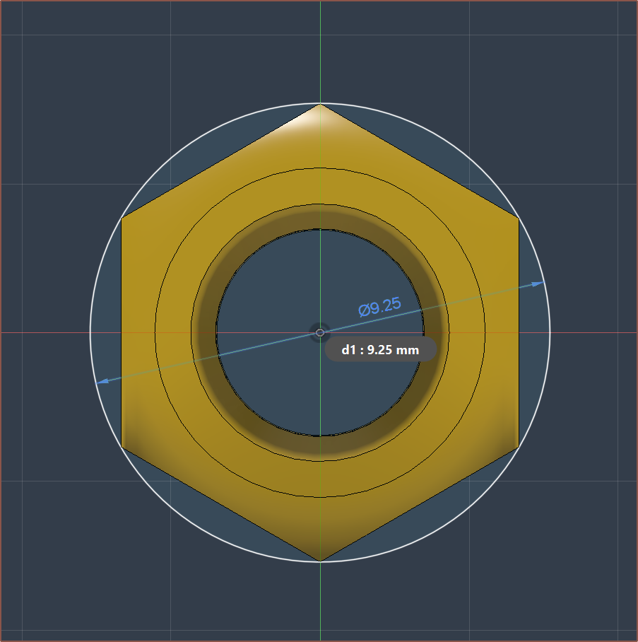
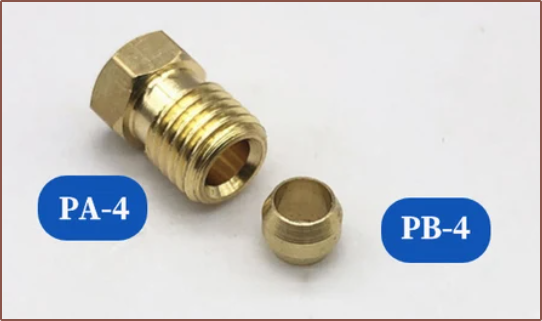
Looking at the internals, I think PCBWay could metal-3D print the internal geometry of the large threaded part, meaning that I only have to consider the space required by the small threaded part, which is only a diameter of 9.25mm or so:
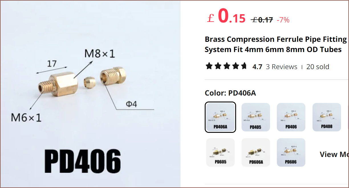
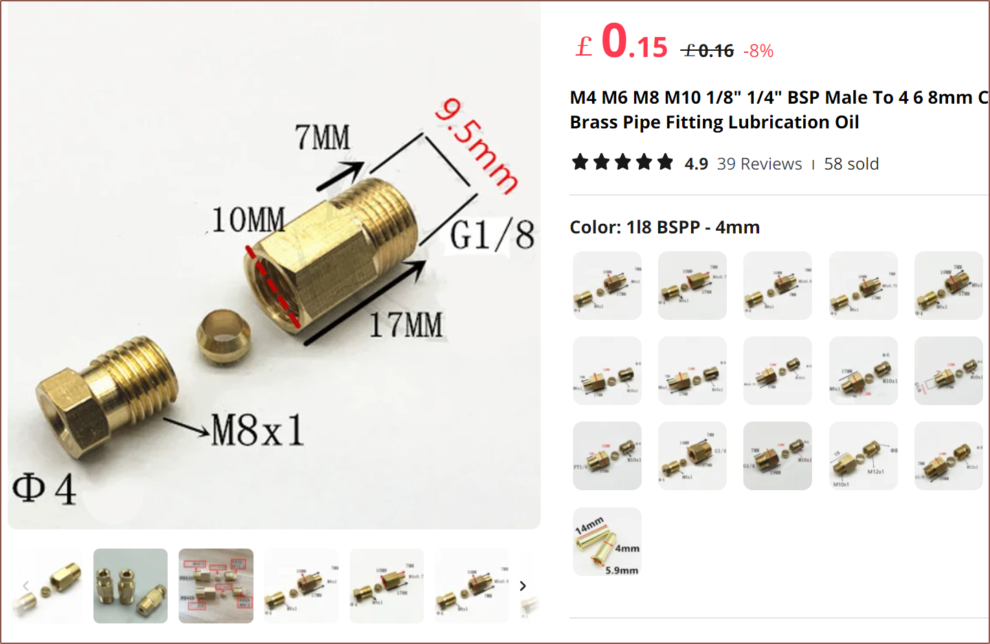
There's actually a few listings that are only the 2 parts I need (on the hotend side):
For the extruder side, I'm thinking of this:
I'm thinking of just getting 20pcs of these because cheaper shipping makes the overal order cheaper.
-
[A] PCBWay CNC fabrication costs USD$257 - $334
10/14/2023 at 12:35 • 0 commentsSo I asked a few questions about PCBWay's CNC assembly service to see if I could get them to basically make an entire heatblock fresh out of the oven and the response sounded positive enough for me to try it.
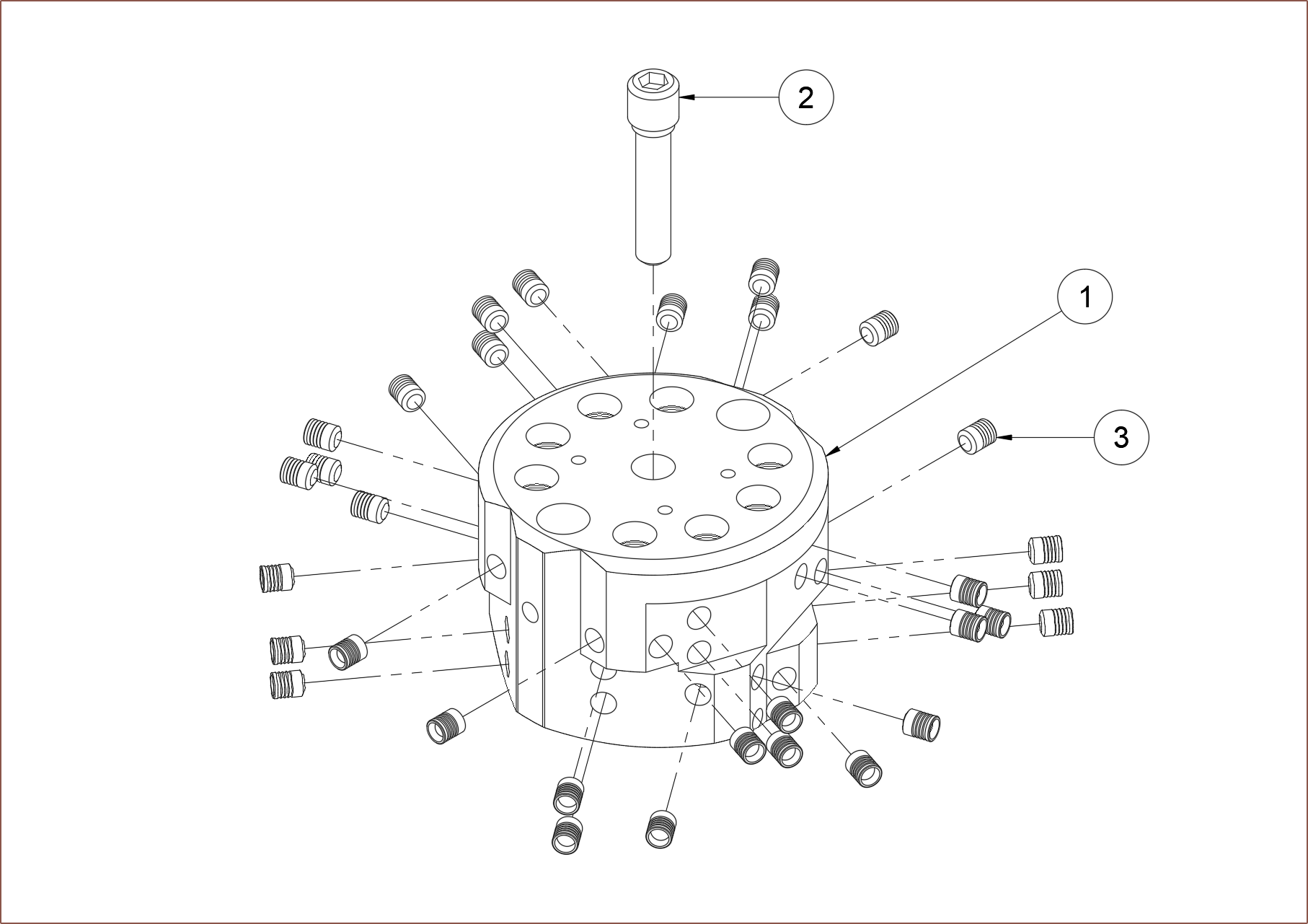
The first thing was to make an exploded view of the assembly, and in Fusion360 this is done though the "Animation" workspace.
I used the transform command to manually move out all the parts so that they're hopefully all visible from this angle and then turned it into a drawing:
From a top-down view, I kept plugs on the same face on the same plane when moved out so that it was more obvious which of them goes where. PCBWay got back to me and quoted $334.08.
I then tried a few different things to see what the lowest was without assembly, such as increasing the center bore from 5 to 6mm (limited by the M7 on the bottom) and deleting the flat faces, but just the main block was quoted $277.52. An aluminium version was $257.69.
Even if I could justify the price and assembled myself, the additional components is at least £70 ($85) ontop of that, and leaks would still be of a concern. Thus, I'm going to take a page out of Apple's book and look into 3D printing a "unibody" coaxial hotend. I'll say more in the next log, but the idea is similar to the B3 hotend:
I've also been reading the research paper by this redditor and it sounds like continuous fiber support (carbon / basalt / copper) is an entire project in of itself; I'd rather put that time towards #SecSavr Suspense [gd0105]. Thus, I'm likely to omit the centre expansion port.
Coaxial8or [gd0144]
Full-colour FFF? Multi-materials with unparalleled interlayer bond strength? Abrasives without abrasion?
 kelvinA


 I realised that I could use a smaller elipse for the body of the hot section. I also tweaked the thermistor cartridge so that less of the hole depth needed to be tapped:


 The next thing to do was to remove the flat face that would require the printer to bridge 90-degree overhangs and replace them with 50 degree overhangs. To get the starting chamfer to work, I first had to offset the eliptical face:
 The end result looks a bit more interesting now:
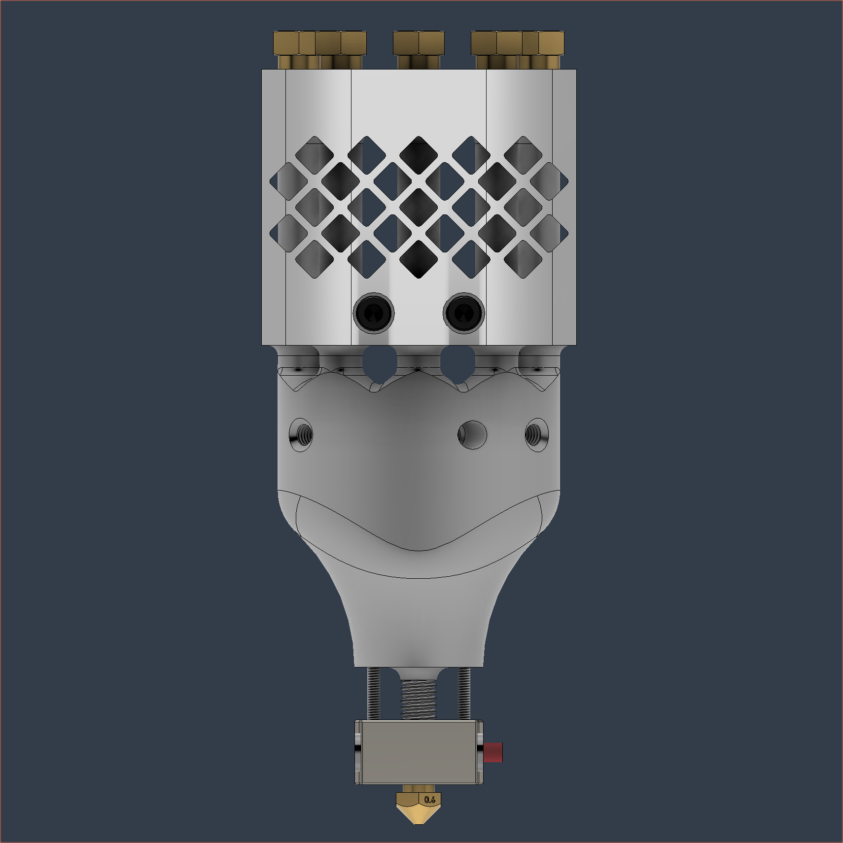 The bounding box (compression fittings to nozzle tip) is 49 x 49 x 124mm and the printed mass is 212g (down from 241g from the first version I sent to PCBway), which is in the same ballpark as 10W+ (output) laser diode module sizes. Unfortunately, it seems this hotend is going to be in the same ballpark in terms of price too.

 I tried a fin-based design and it slightly improved things, but still nowhere near good enough. It seems that "it's over.", with the only mitigation strategy I can think of being to reduce the amount of material that makes up the vertical tubes by modelling a mesh design.
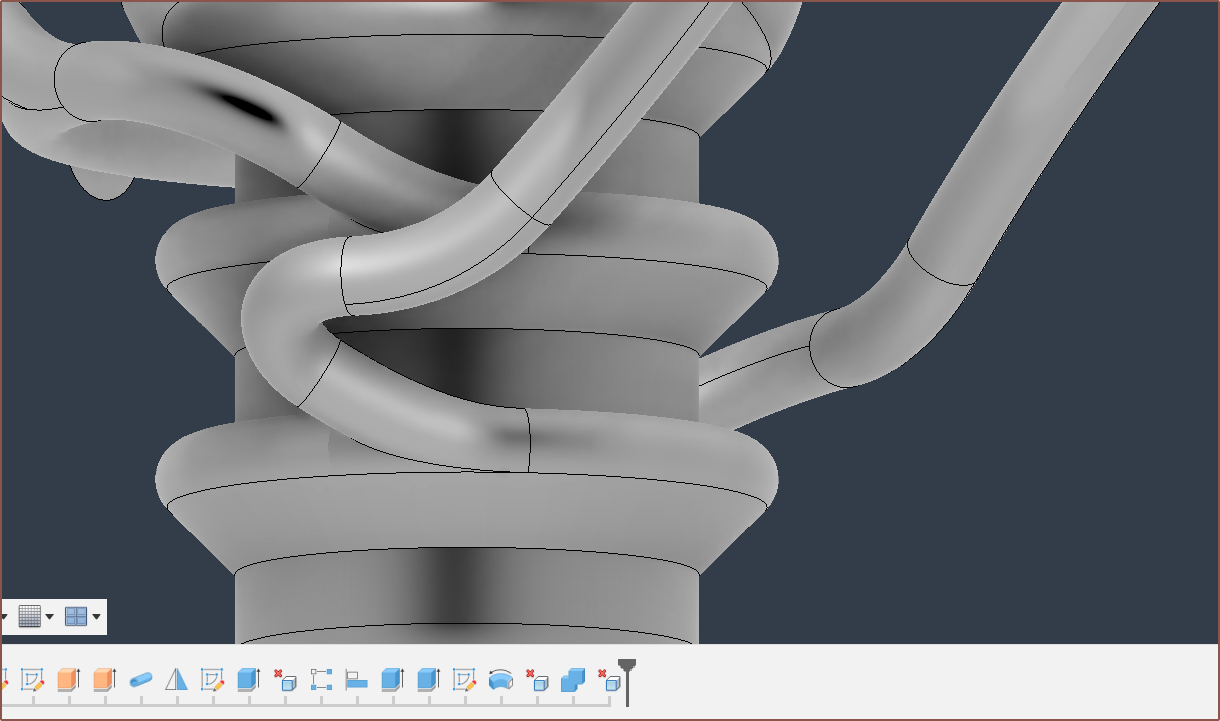
 However, I'm not so keen on the timeline noise (see below) nor the fact that only things that are in the active component can be fastened (though this is mitigated for the most part as all fasteners go into their own folder).

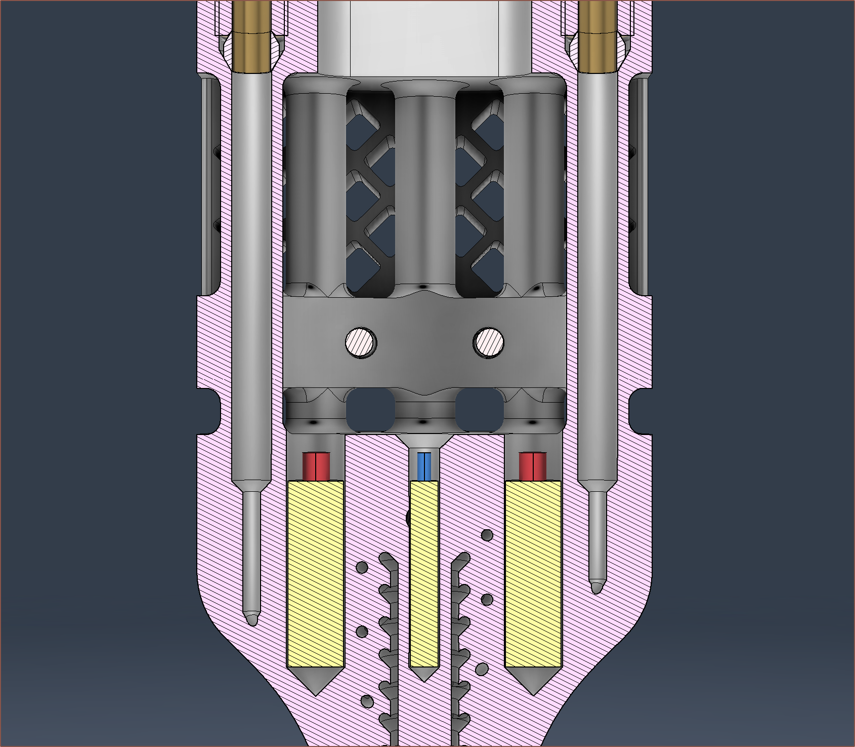
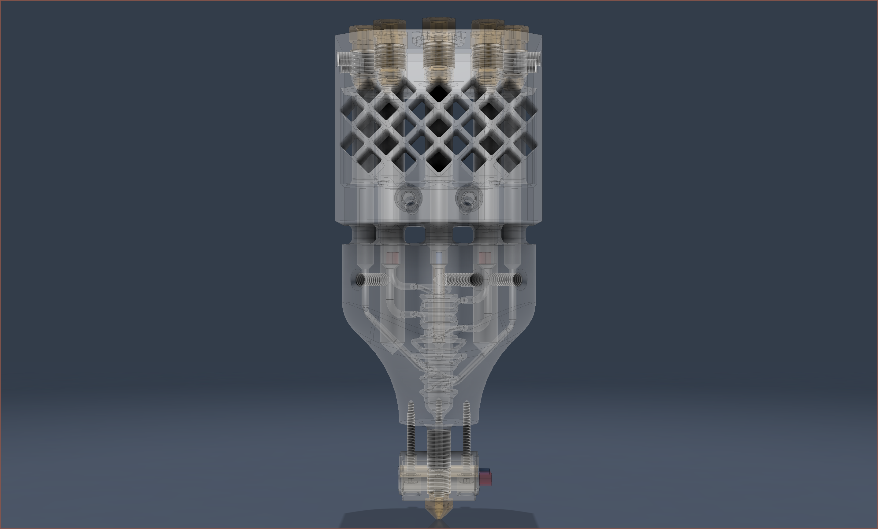
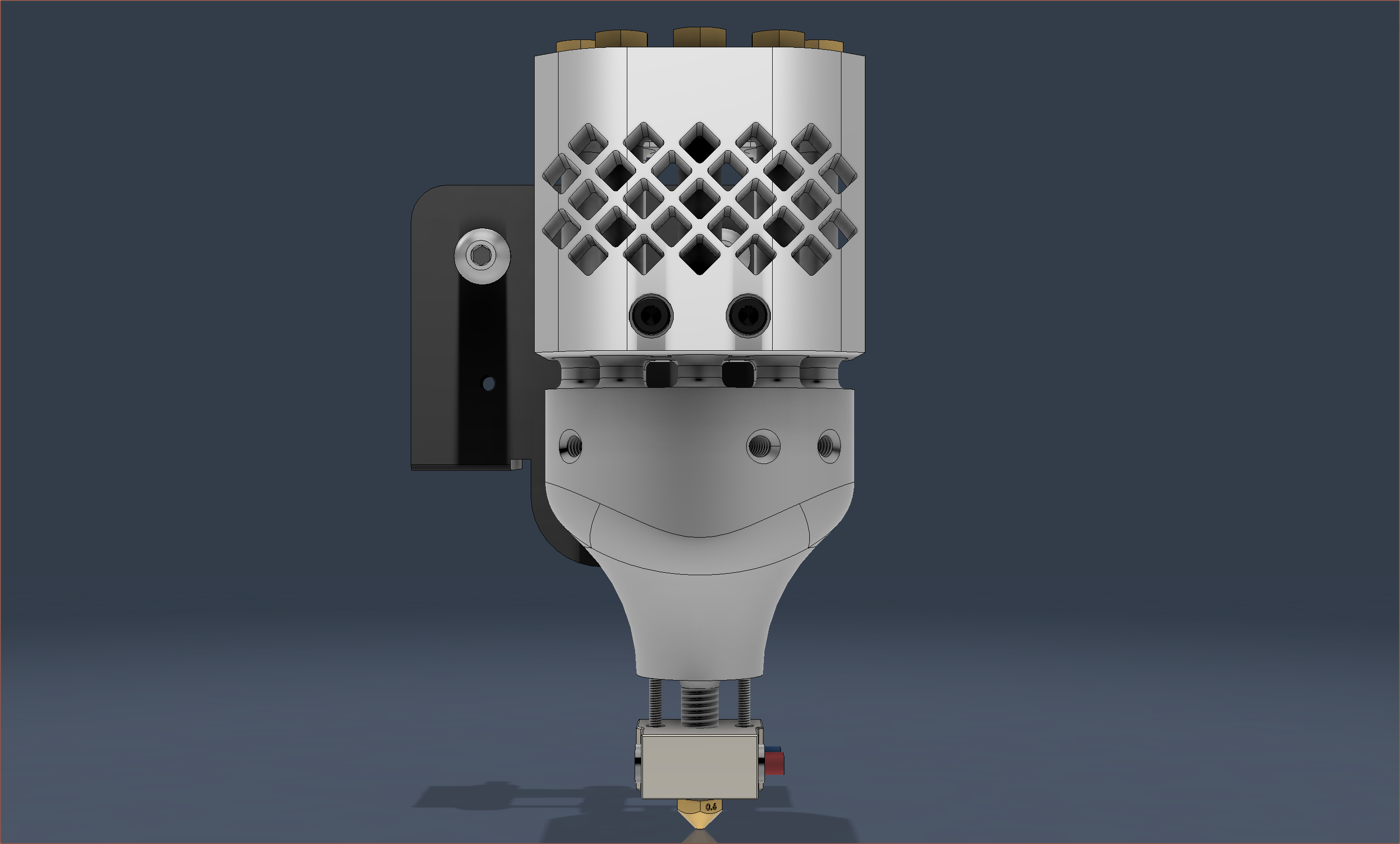


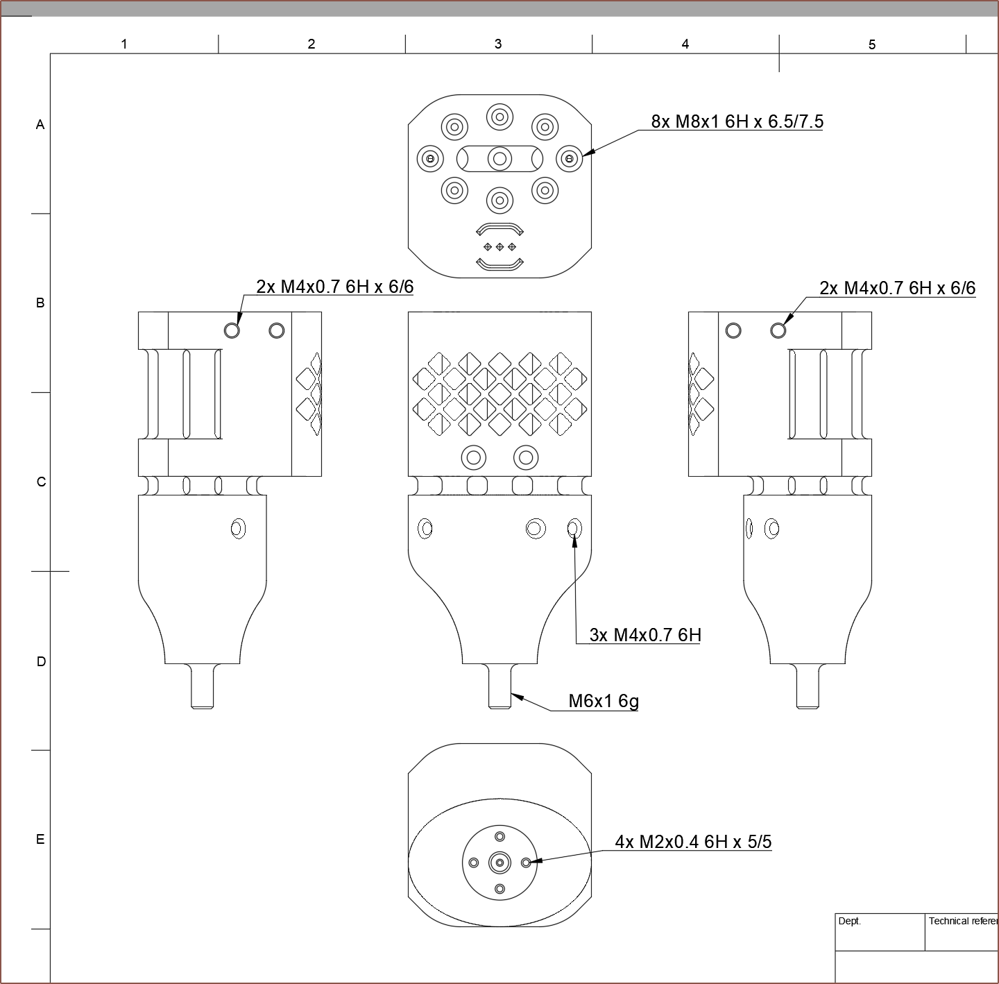

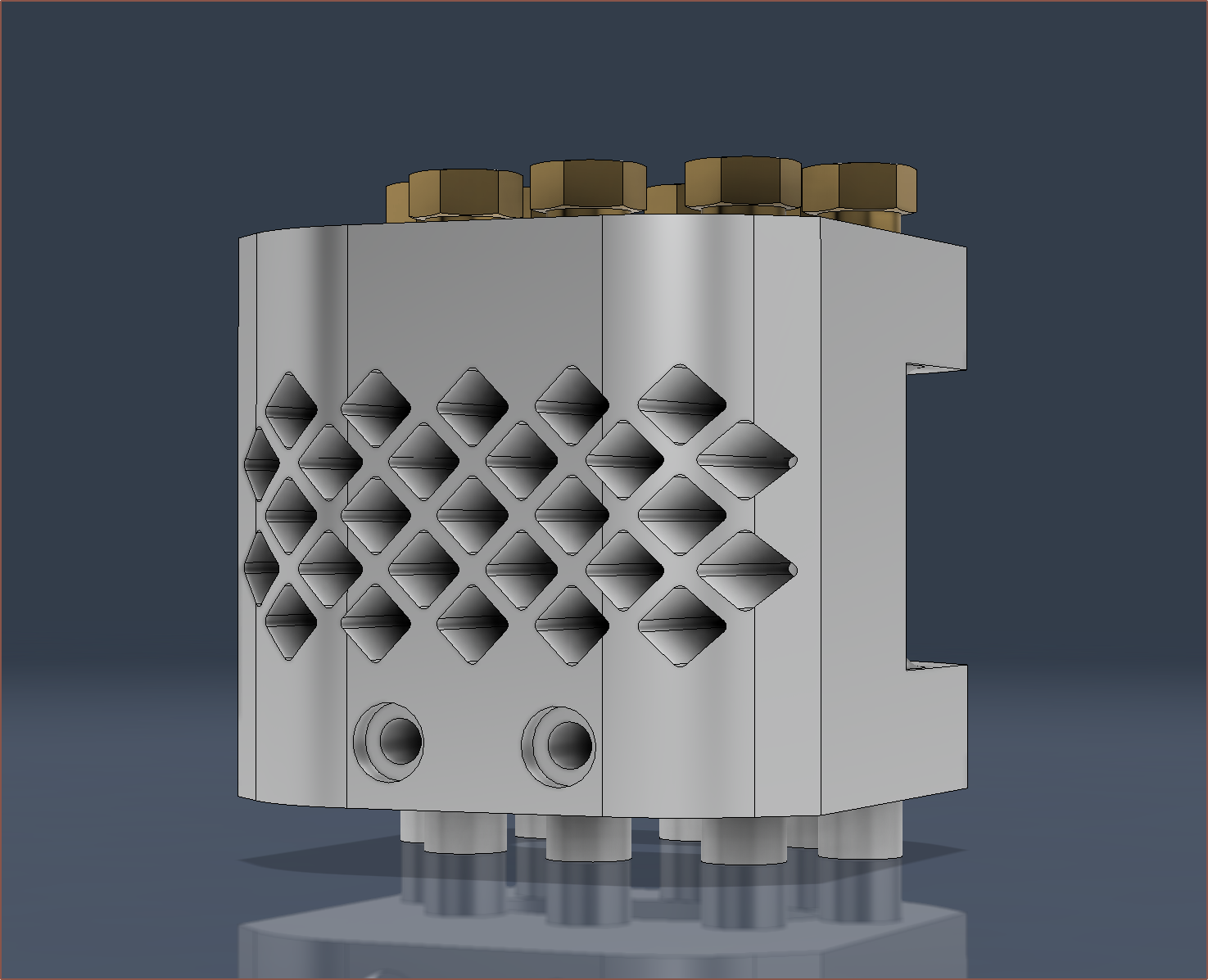
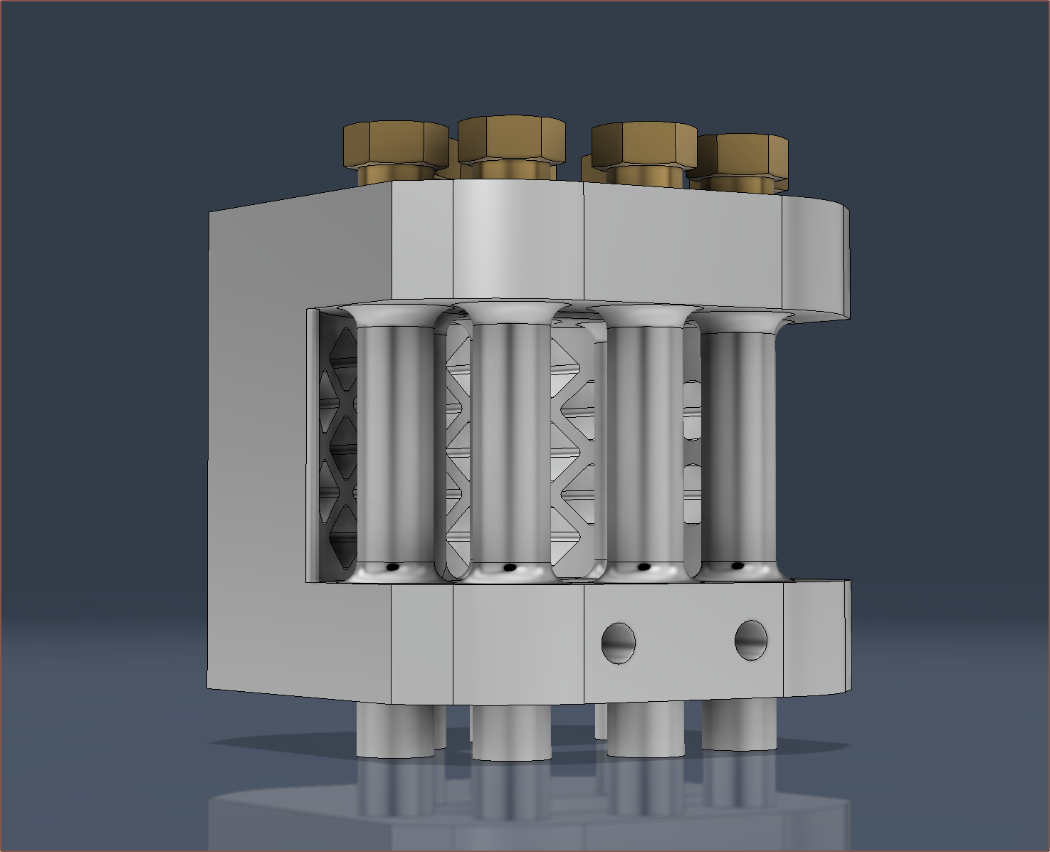
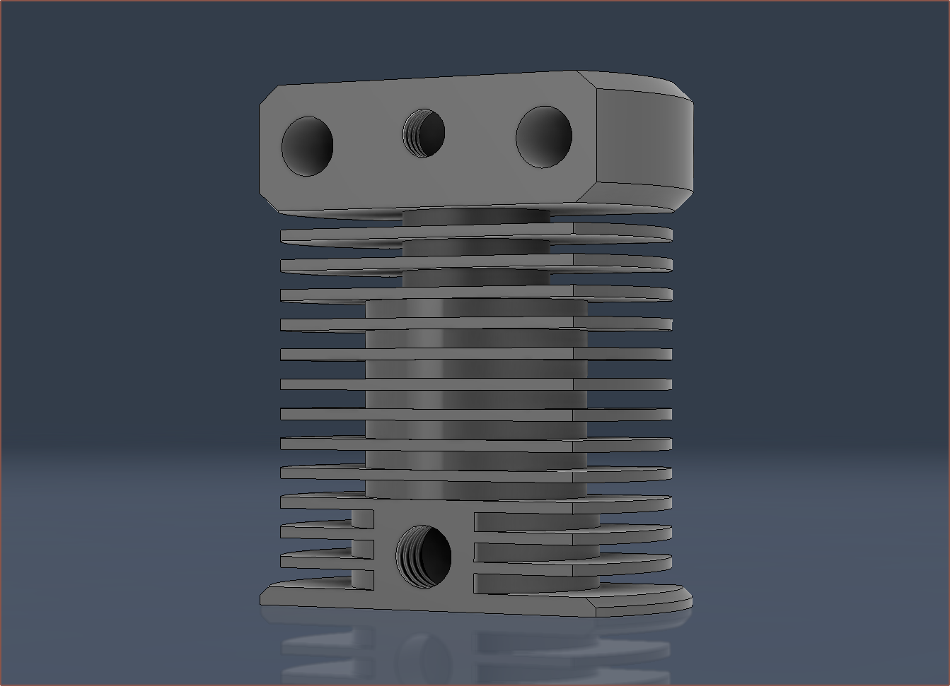
 For the PTFE compression fittings, I've used the Fusion360 hole feature, with a bottom angle of 60 degrees, thread depth of 6.5mm, total depth of 7.5mm and thread of 8x1.

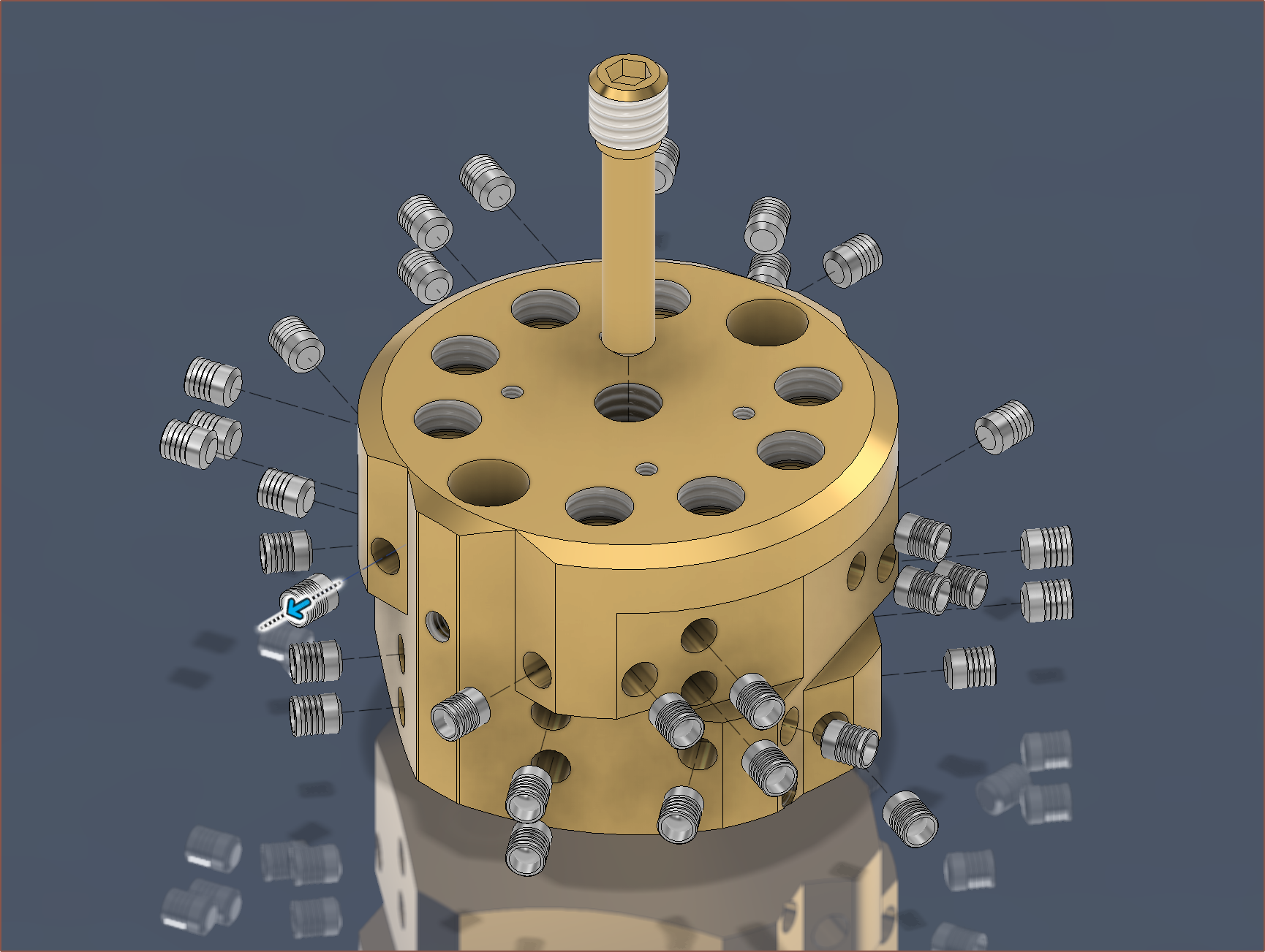 I used the transform command to manually move out all the parts so that they're hopefully all visible from this angle and then turned it into a drawing: