Close
0%
0%

The Circuit Graver

Carve PCBs at home using a machine you build!

Similar projects worth following
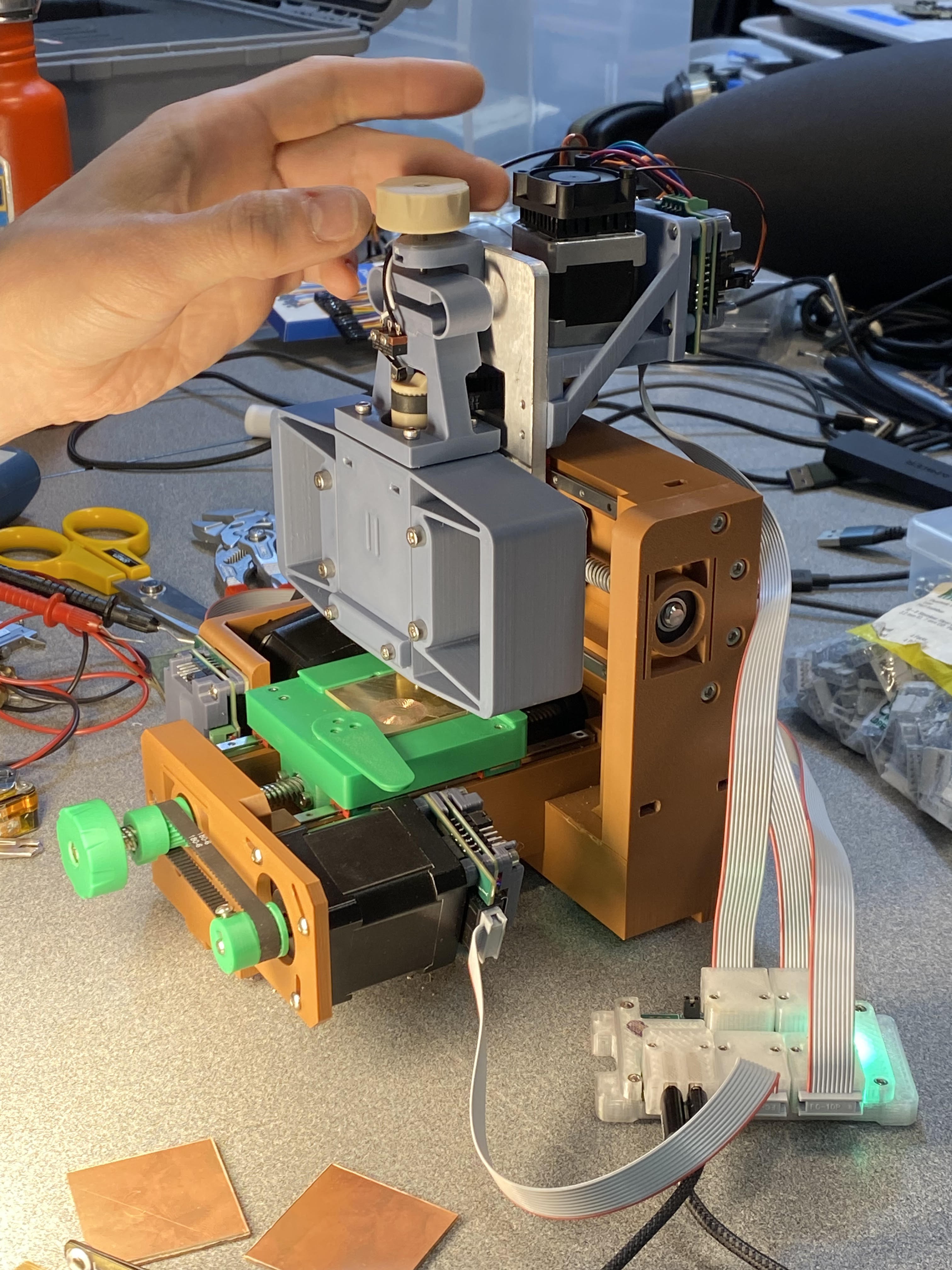
A small 3D-printed 4-axis machine I designed and fabricated to carve circuit boards at home! The Circuit Graver is very much a work-in-progress / proof-of-concept, but it's made a few functional boards and can achieve finer feature sizes than a desktop mill in much less time.

The Circuit Graver is a small four-axis CNC machine which quickly and precisely carves single-sided circuit boards. The unique cutter design uses a repurposed carbide turning tool to gently create trenches in a 40x40 mm piece of FR4, isolating adjacent conductive nets much like a circuit board mill. Using this method has a few key advantages over milling: it's faster, operating at 20-30 mm/s rather than 2-3 mm/s; it's quiet, since there isn't a high-speed rotating spindle; and it can achieve smaller feature sizes, comfortably 8/8 mil design rules (0.20 mm spaces and traces) and marginally 6/6 (0.15 mm). That means the machine can be used for same-day prototyping of simple circuits using modern 0.5 and 0.4 mm pitch components, like fine-pitch QFPs, QFNs, DFNs, and 0402 discrete parts.
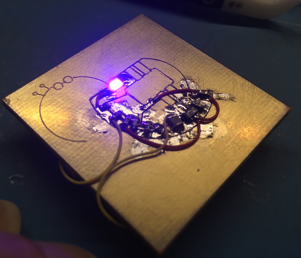
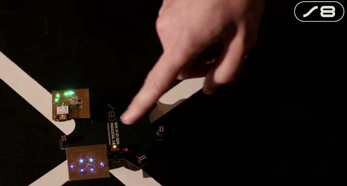
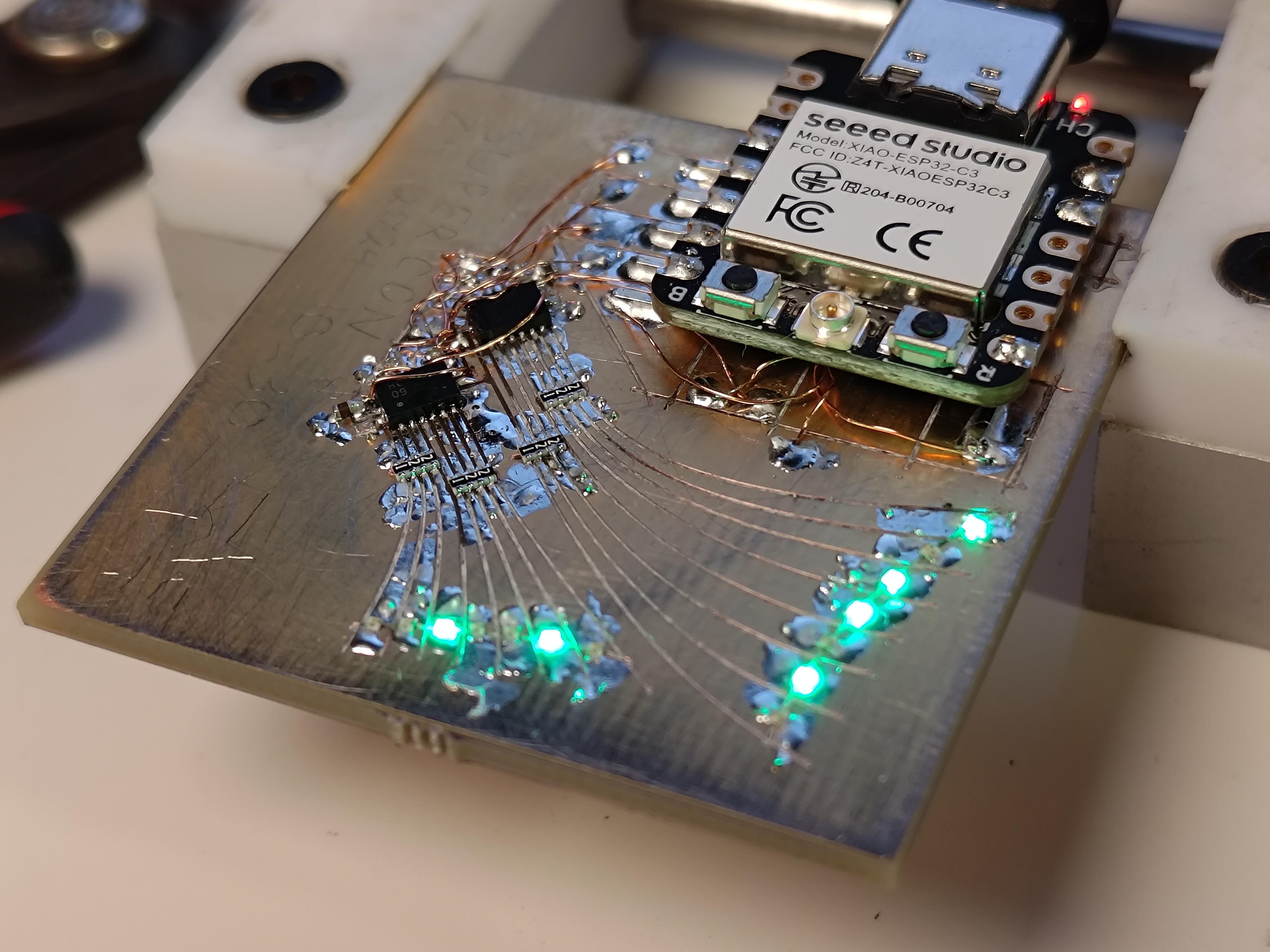
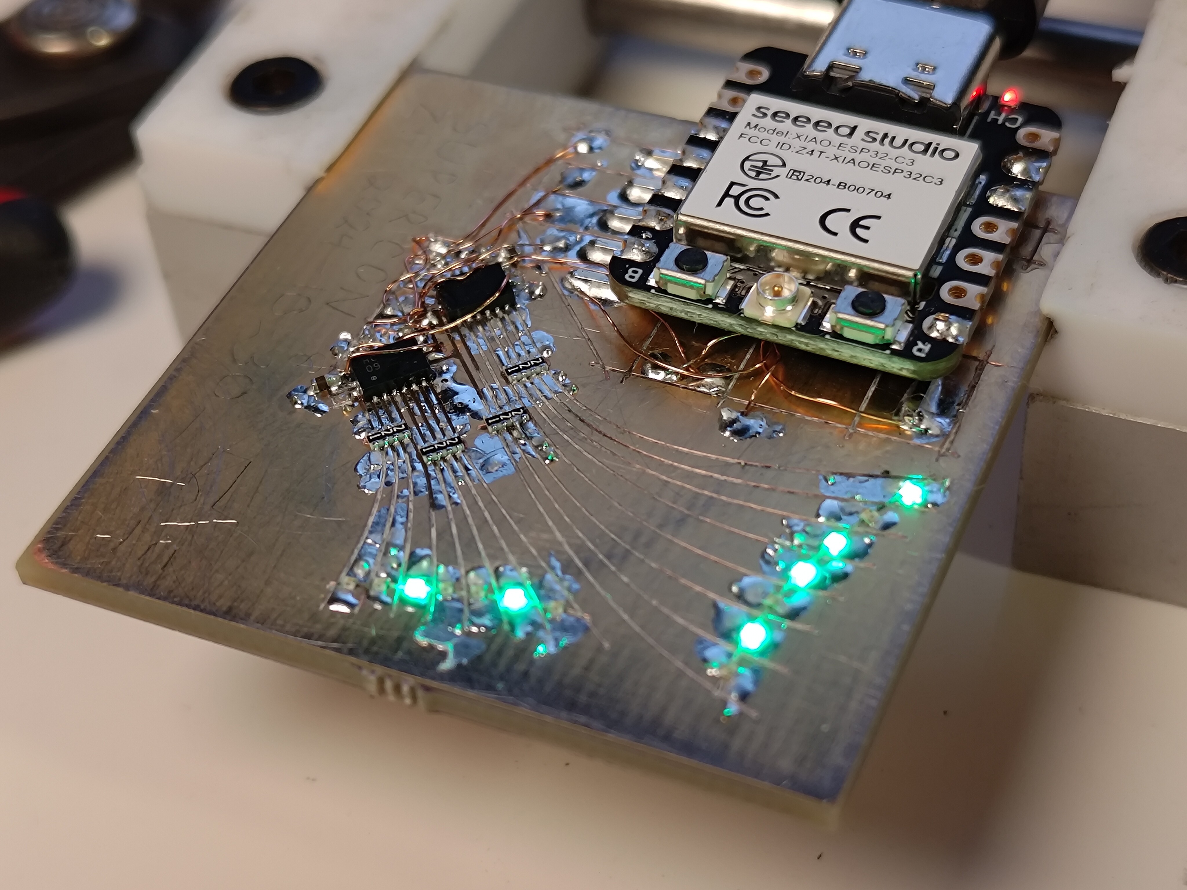
As of 2024's Supercon 8, the machine has been operational for around two weeks and I have used it to produce a few dozen test boards, and three working circuits, one of which came together the night before leaving for Pasadena and one of which I designed and fabricated at the conference. The first two circuits are the most interesting, and use tiny DFN 74HC595 shift registers driven by ESP32C3 XIAO boards running Micropython to blink a bunch of 0402 LEDs. Board One uses yellow LEDs and a single shift register:

... while Board Two uses green LEDs in a more interesting pattern and two shift registers:
And an update, from Pasadena on the morning of my talk! I also used it to design and fabricate Board Three, a simple add-on with a Supercon8 theme, which I'll add a photo of here at some point. Perhaps the first custom machine-fabricated circuit board to be made at the conference? I can't imagine no one brought a desktop mill at some point, so I won't claim that yet.

Here is a video clip of the mounting pads for the XIAO getting carved into the first board. Keen observers will note that I did this after assembling the delicate shift register bits, a dicey proposition for the only working artifact produced at that point by a machine I wanted to show off in a few weeks:

As seen above, there are still fundamental limitations to the process which are shared with other home-gamer techniques: no vias, no solder mask, and in this case, no singulation. Carving circuits also needs a thorough trip through optimization-land; the whole process is quite finicky, requiring careful pressure adjustment and minor razor-blade fixes on perhaps 10% of traces. The concept would also benefit from more specialized toolpathing to reduce the chance of tearing up the corners of traces at right angles (among many other minor tweaks). Think of this as super-duper-early-stage research that just had completed its first spiral; the field is pockmarked with hastily covered rabbit holes, some of which may be filled with gold (or gremlins, to be fair).

But all faults can be forgiven when one sees the adorable and satisfying tiny chips getting produced during operation (okay, technically this is a shot from the manual test jig, but you get the idea):

I designed and fabricated The Circuit Graver in my tiny Cambridge apartment in 3 months during the fall of 2024, using primarily 3D printed parts and linear motion components acquired from eBay. This nights-and-weekends project received major a kick of extrinsic motivation when my proof-of-concept manual test machine got me a speaking slot at Supercon 8, and it really did come together at the last moment. A huge thanks goes out to Jake Read, my friend and colleague who offered up his distributed machine controllers and associated control software and allowed me to focus on mechanical design and cutter testing. You should check out his work here, and his current / my former lab here, where I learned how (and why) to build machines. The Circuit Graver's controls are built on the next generation of modularthings; once Jake has published and shared his work I'll update this project to include software source files....

Read more »

the-circuit-graver-ii v42.f3z

Fusion360 model of the mechanical bits, so you can see all of my CAD crimes. Some minor hardware (like bolts and nuts) is missing, and the assembly isn't joined, just aligned.

f3z - 13.49 MB - 11/02/2024 at 13:15

Download

LICENSE.txt

Open-source license for the mechanical parts of the project! CC-BY-SA 4.0: https://creativecommons.org/licenses/by-sa/4.0/deed.en

plain - 19.71 kB - 11/02/2024 at 13:14

Download

circuit-graver-3dp.zip

Print with PLA, 15% infill, 5 perimeters, flexures flat to bed, with supports. Fits are tight so prepare for some sanding!

x-zip-compressed - 1.08 MB - 10/31/2024 at 00:31

Download

circuit-graver-cut.zip

Cut this file out of 1/4" (6.35 mm) aluminum plate, and tap the requisite holes with M3/M4 taps. See the CAD model.

x-zip-compressed - 1.53 kB - 10/31/2024 at 00:33

Download

  • 28 × 3D printed parts 28 in all! See instructions.
  • 1 × aluminum plate with tapped holes, see instructions.
  • 4 × MGN5 rails 115 mm length, tapped
  • 8 × MGN5 carriages
  • 3 × GT2 belts I will double-check lengths and update, haha

View all 16 components

  • an article is live. and another data point appears in the comments!

    zakqwy11/07/2024 at 14:48 0 comments

    Dave Rowntree and I chatted a bit at Supercon and he ended up writing a nice article for Hackaday on the machine. Thanks Dave!

    https://hackaday.com/2024/11/06/rapid-prototyping-pcbs-with-the-circuit-graver/

    One of the great things about seeing your project get a bit of press is that it can get enough coverage that interesting people with relevant experience chime in. That seems to have happened here! A commenter named Shara linked to a few pictures which used a used drag knife to carve up a bit of copper-clad substrate, and it looks like they got great results: 

    https://imgur.com/a/RwRdv00

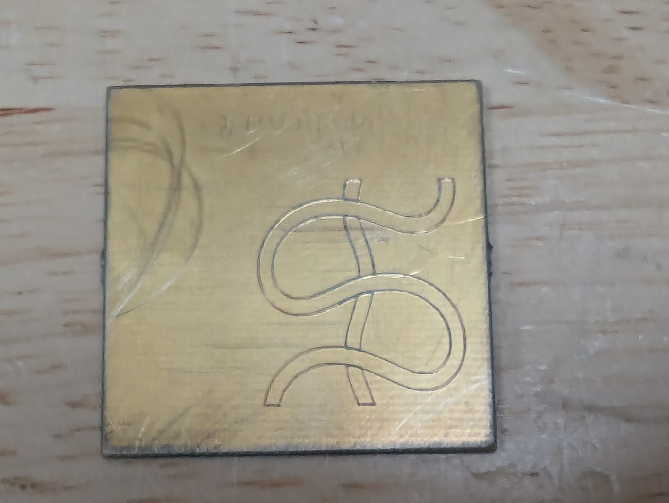
    Copying the photos here in case the imgur link dies; as suggested above, these aren't my photos:

    Shara! Whoever you are, please send a link to your project so I can include it here. These tests look like thin FR1; it seems you might have had the same challenges I had with entry/exit points shorting, but got it to work in the end with hand touch-ups or maybe toolpathing improvements. I'd love to learn more about your setup and see a video of it in action! What feature size can you hit? How fast? Does the cutter get dull quickly? What kind of machine is it driven by?
  • in pasadena!

    zakqwy11/02/2024 at 13:12 0 comments

    I finished the SAO at the eleventh hour, the day before getting on a plane. It works! Well, one LED has some challenges, but we're counting this as a win. It's also a great example of why vias are important; driving two shift registers means they share a lot of pins and need a lot of tedious (but delightful, of course) magnet wire work.

    At some point I'll post more pictures, maybe installed on the badge. But for now:

    The machine made it to LAX without much trouble, and I managed to spot it getting unloaded from my (well, Delta's) 757-200:

    I got to Supplyframe HQ around 4 PM and set up on a table with friends, and spent a few hours showing folks how the machine works and making sample boards. And soliciting designs from conference attendees! I brought ~30ish blanks and it would be great to go home with none.

  • soldered the fussy(est) bits!

    zakqwy10/31/2024 at 12:12 0 comments

    I got up early and soldered the DFN HC595s and 0804 resistor packs before heading to work:

    I used braid to clear a few obvious bridges and checked resistance pad-to-pad across the resistor networks. They were a bit fussy to solder because of the aforementioned circuit carving gore; I had to reflow a few of the pads and one of them ended up needing a tiny length of bodge wire to bridge a gap in the copper. But after not too much work each trace beeps out as it should and I didn't detect any bridges between adjacent nets! The other stuff (LEDs, a few bypass caps, the ESP32, and the SAO header on the back) is pretty low-risk, so I don't anticipate any issues with getting this woken up this evening with a few hours to spare. Huzzah, etc

  • curvy leds + fab

    zakqwy10/30/2024 at 22:00 0 comments

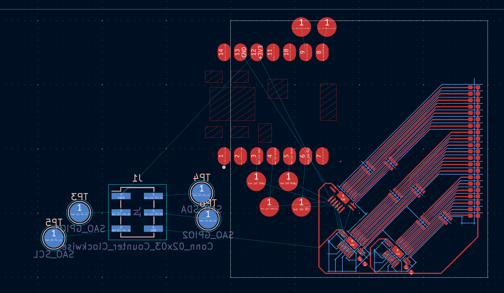
    I used Inkscape to make the LEDs a bit more interesting:

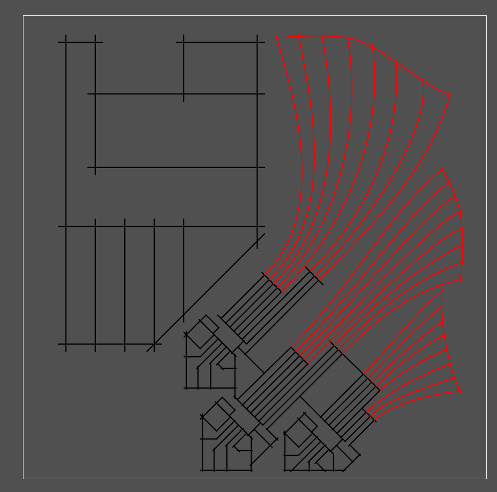
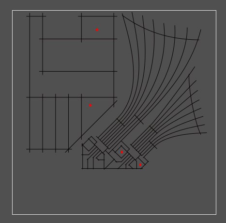
    After a quick air-cutting fab test, I de-escalated the LED count to save Y-axis travel:

    [yup, screenshots of inkscape]

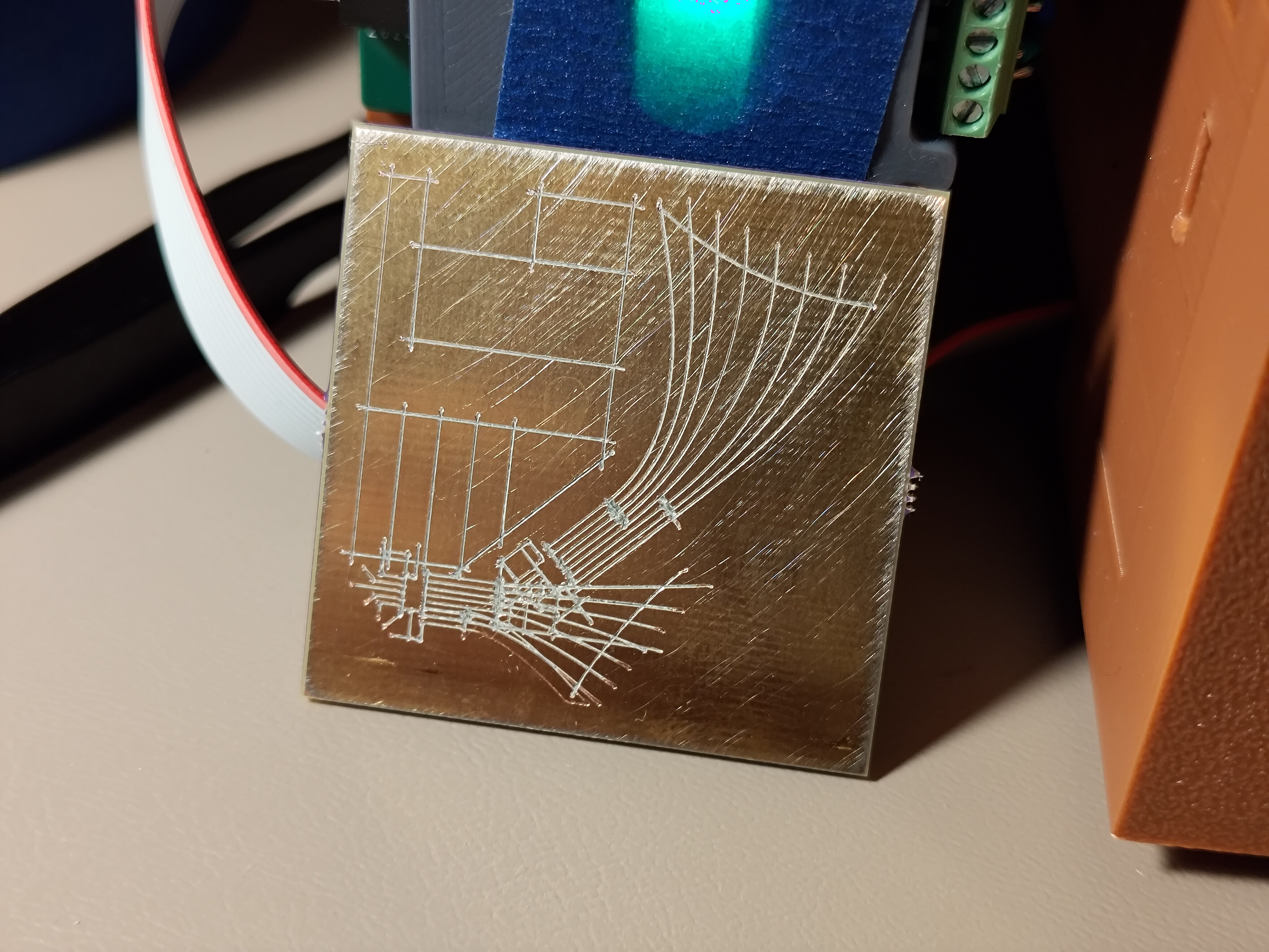
    The red dots are shorts to ground or adjacent pads after fab. Not bad! The first round was weird, though; I kept the lower LED cluster grouped and saved as an Inkscape SVG (as opposed to "plain"), and the grouped bits didn't rotate properly:

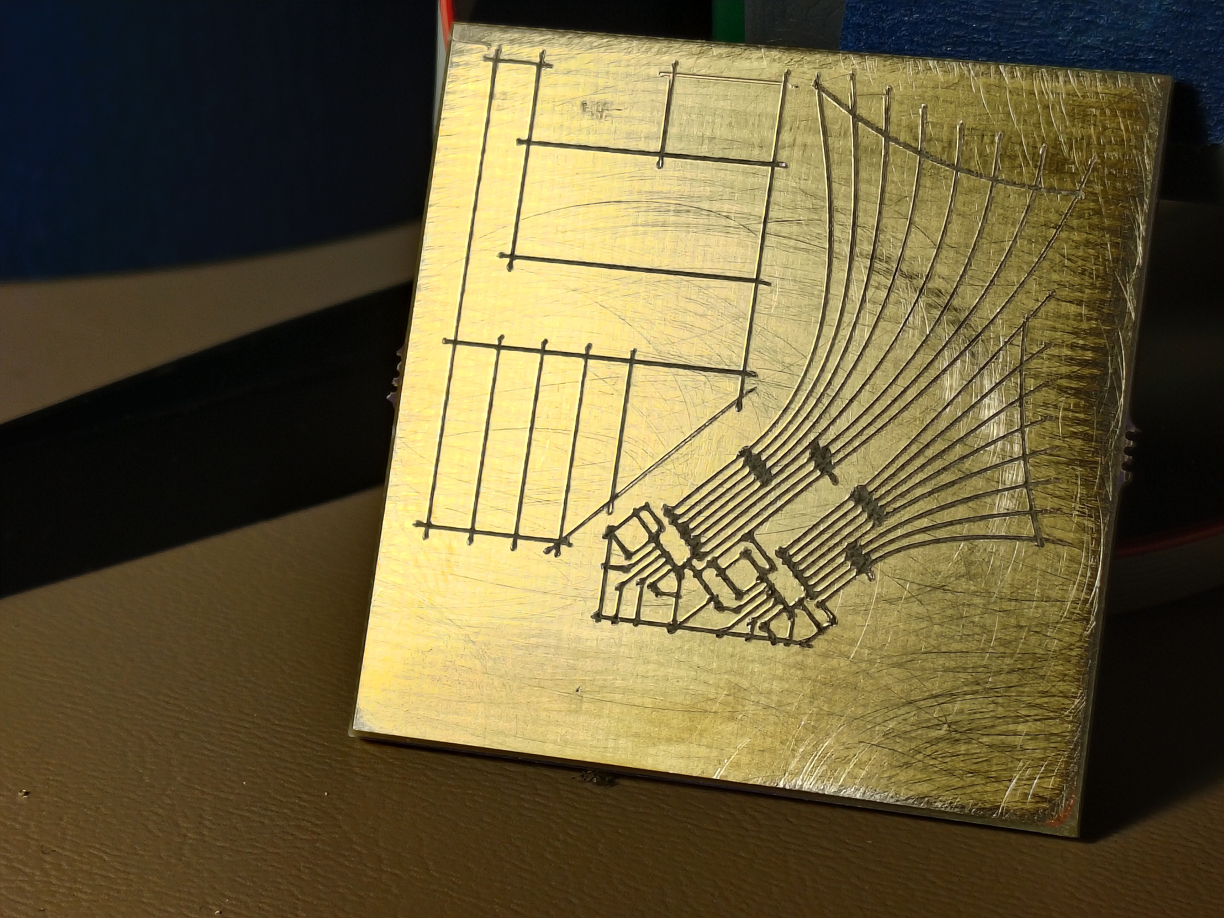
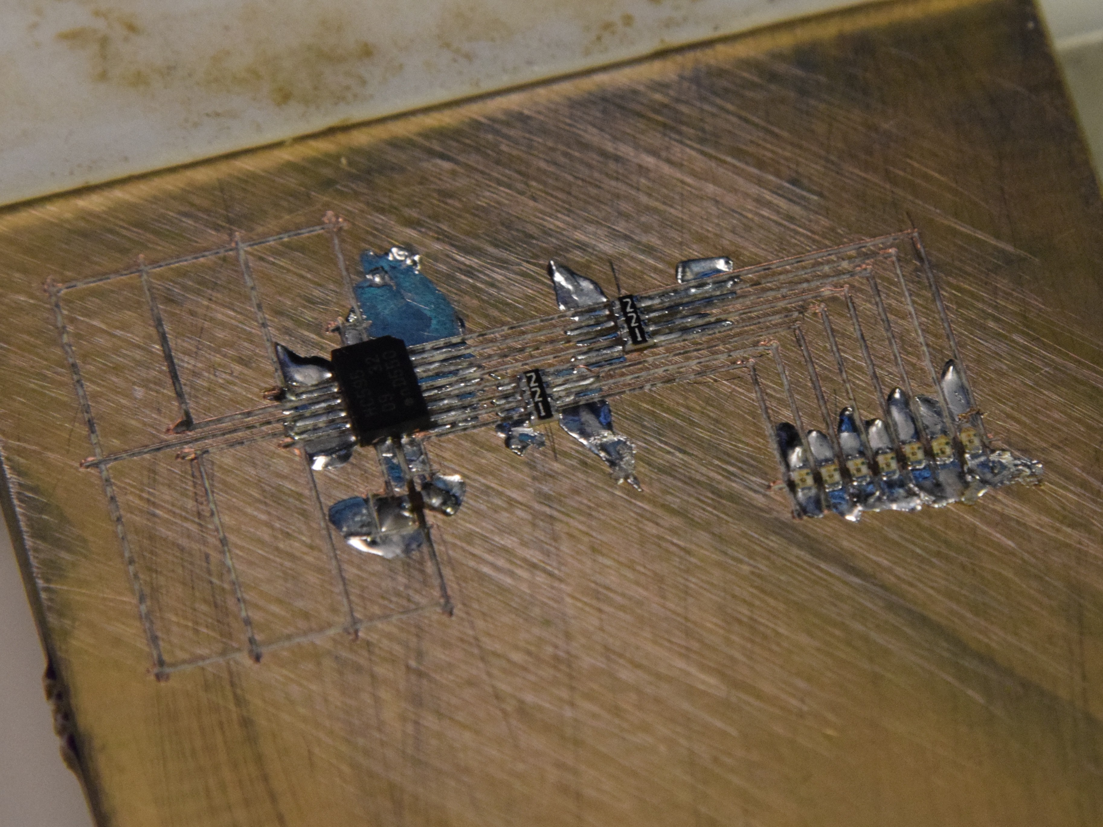
    Mmm such fascinating gremlins. I un-grouped and re-saved and ended up with a good board which beeped out after fixing the aforementioned shorts (fewer than last time!):Oof, the resistor packs are particularly gruesome. 4-way crosses aren't great. Some toolpathing cleverness for narrow trace areas is really going to be necessary at some point; crossing trenches can pull pretty severe chunks out around narrow feature areas. I think this is solvable but will take a bit of experimentation.
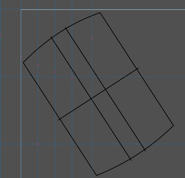
    Now for the header pads on the reverse side! Since the badge design is released, I was able to adjust the angle so in the upper left plug the square would sit upright (roughly 33 degrees):

    Fab was perfect, beeped out on the first try! I wasn't shy with the pressure wheel since this is such a simple design, but it was nice to have one require no work either way. I might be able to back off the overcut a bit, in fact:
  • slides and a sao sprint

    zakqwy10/29/2024 at 02:56 0 comments

    Slides are turned in! Sent yesterday evening, a day ahead of the double-extended deadline. Tonight, I decided to make a badge add-on, now that we know the conference badge is a carrier. Nothing crazy! An extension of the first test circuit, again using tiny but easy to use parts I have on hand: three shift registers, 21 LEDs (since the 8th digit is hard to route without vias), six resistor packs, the same ESP32C3 XIAO board, and a 6-pin add-on header on the back. I have enough blue, green, and yellow 0402 LEDs, and will likely go green this time. Would be great to have orange, but time is short.

  • the circuit works!!

    zakqwy10/23/2024 at 03:50 0 comments

    Reckless! I re-fixtured my lovely circuit (the only complete circuit I've made so far) and carved in another set of pads to suit an ESP32C3 XIAO module from Seeed Studio. I flashed a fresh Micropython bootloader and wrote a few lines to fill the shift register with 1s and 0s with 0.5 s delays.

    It works!

    For now, sleep; but to come, more images, some notes on the design workflow, a video of fabrication (carving on the same board as a bunch of soldered parts, ack!), a bit of code, a discussion on the various repairs and bodges it took to get here, a love letter to 34 AWG polyurethane-insulated magnet wire, etc.

  • a circuit!

    zakqwy10/22/2024 at 01:59 0 comments

    Oof, behind on updates; I spent a great Saturday back at the CBA where Jake helped me wake up the rotary axis. We carved a lot of bad circuits and a few good ones; after a few manual touch-ups, one beeped out so I soldered on the appropriate components:

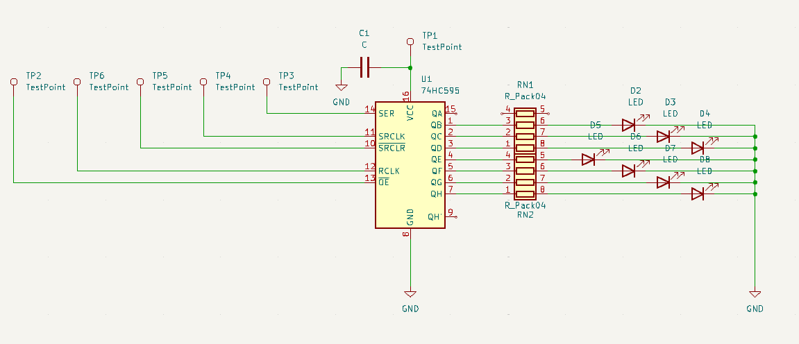
    It's not a complicated circuit, just an HC595, a pair of 220-ohm resistor packs, and a handful of yellow 0402 LEDs:

    Not yet tested, but no shorts! Tomorrow(ish), I'll drop some wires on the six driver pads and see if I can make some blinkies happen with an external driver IC of some kind.

    And more to come! Lots to show: pictures and videos and failures and heatsinks and limit switches and the rest. Slides are now due in a week, but I'd rather not push that, so I may prioritize the talk over updates here for the time being.

  • time for some circuit carving!

    zakqwy10/13/2024 at 20:34 0 comments

    Okay, a good bit to catch up on here! First, some early results, featuring a 0.5 mm pitch DFN-packaged 74HC595 left over from #blinktronicator builds oh so long ago:

    X/Y/Z axes are working! Everything is working, with a big caveat that I'm not quite getting the result quality I'd like. Of course, I'd really like 150 micron (6 mil) spaces and traces, but that seems to be right about the limit of the technique. I picked up a cheap USB microscope and got some images of carved trenches with 0.3 mm stepover:

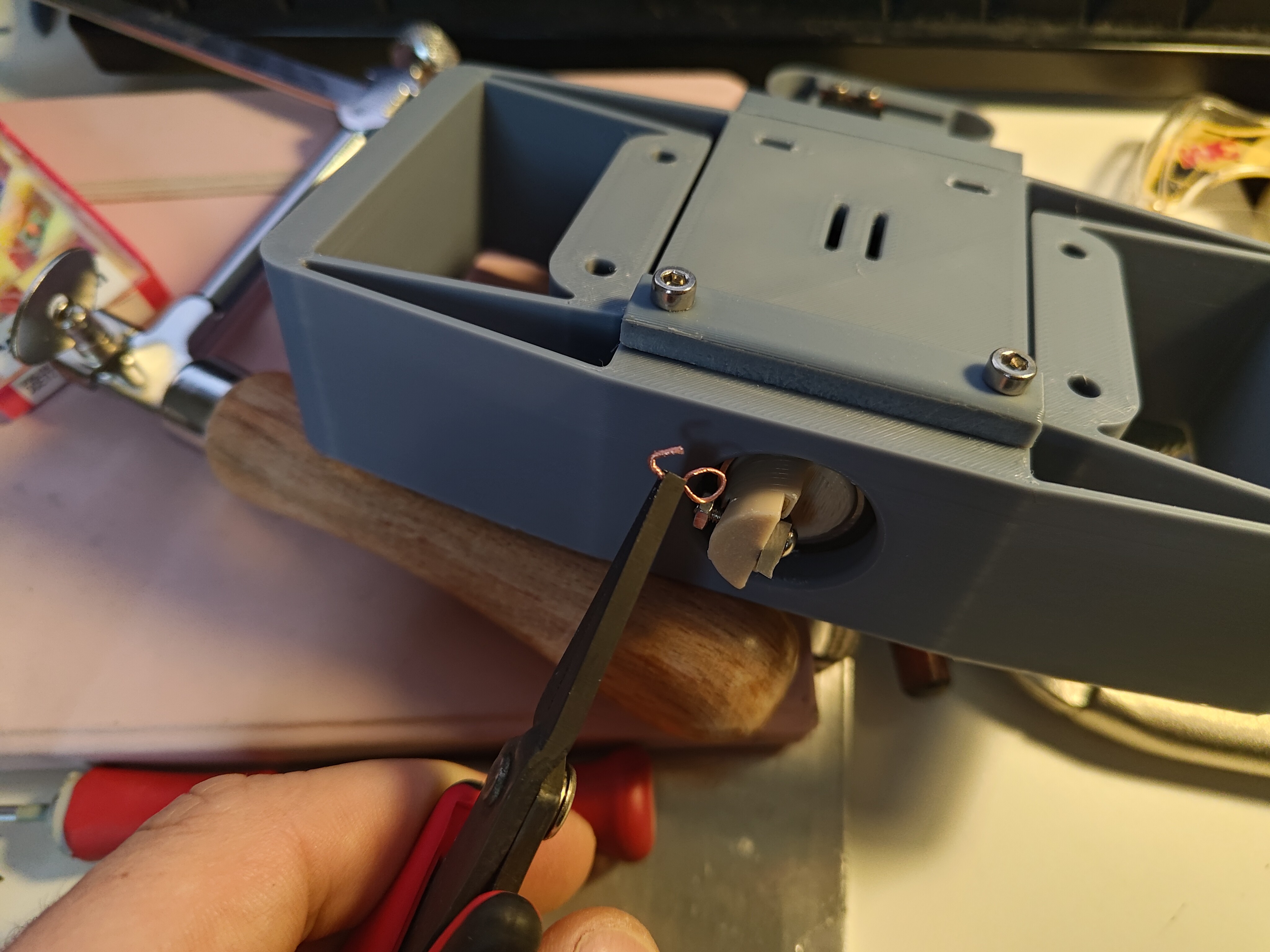
    Many interesting things to note from test 16! First, specs: 20 passes, 0.3 mm spacing, 10 mm long strokes, a thinner 1.2 mm Z-axis flexure, and 1.5 turns of the pressure knob after touching off the material. I started doing this by checking continuity between the cutting tool and the PCB which works well, but is a bit awkward; a loop of wire attached to the tool helps a lot, as it provides a place for one multimeter lead to rest:

    Second, the entrances and exits are dramatically different; you can see how the cutter digs its way down to the right depth, leaving a bit of unusable area at the front of the trace, then stops clean. Note that these photos are after a quick 320-grit deburr, so the curly chips are absent. Before sanding the cuts look something like this:

    That was from a slightly lower pressure run, probably 1.0 or 1.25 turns past touching. Note how much the copper smears down the trench! In one case it completely bridges the gap, but even in the others it looks like there may be some hairs crossing from one side to the other. I think that means, at least for this setup (cutter, flexure, etc), 150 um trenches might be a reasonable minimum.

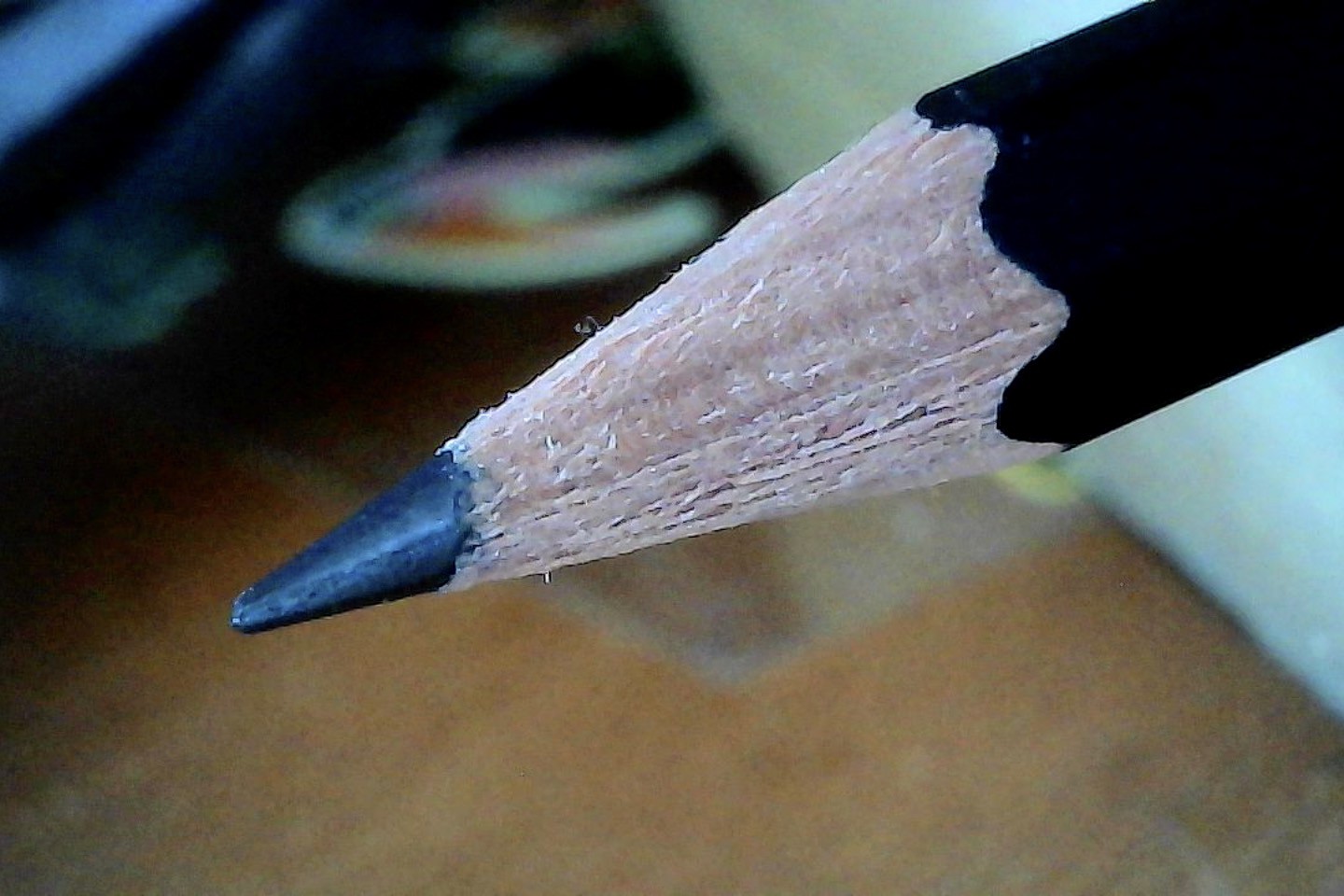
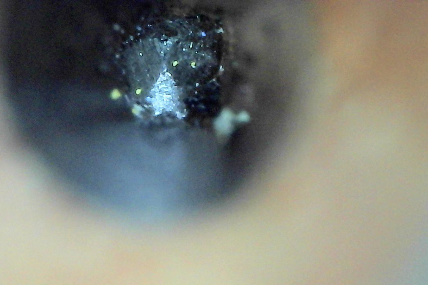
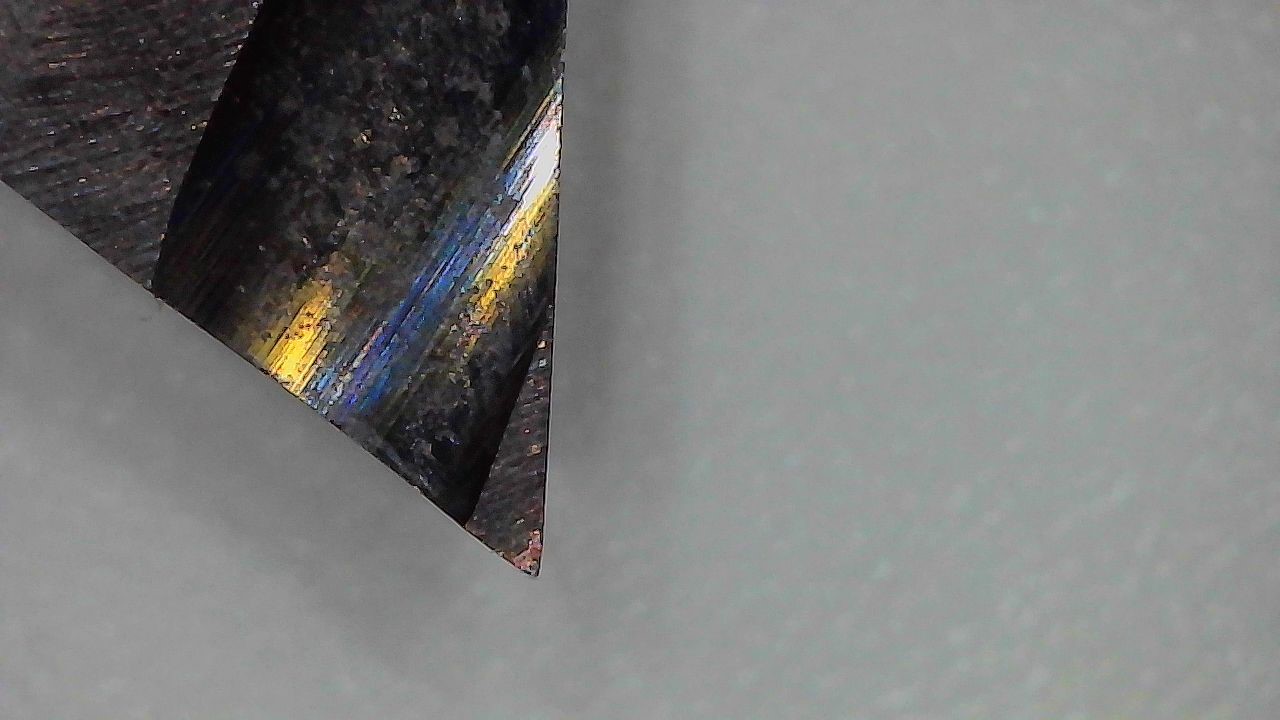
    The tool looks okay under magnification, maybe a bit rounded at the very tip, but still pretty sharp:

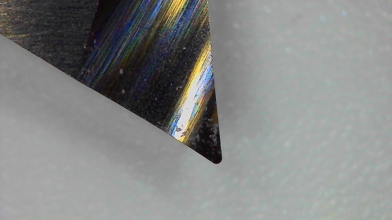
    For comparison's sake, an unsharpened tool shows off its 0.1 mm tip radius:

    Here is the old 1.6 mm Z-axis flexure next to the new 1.2 mm version:

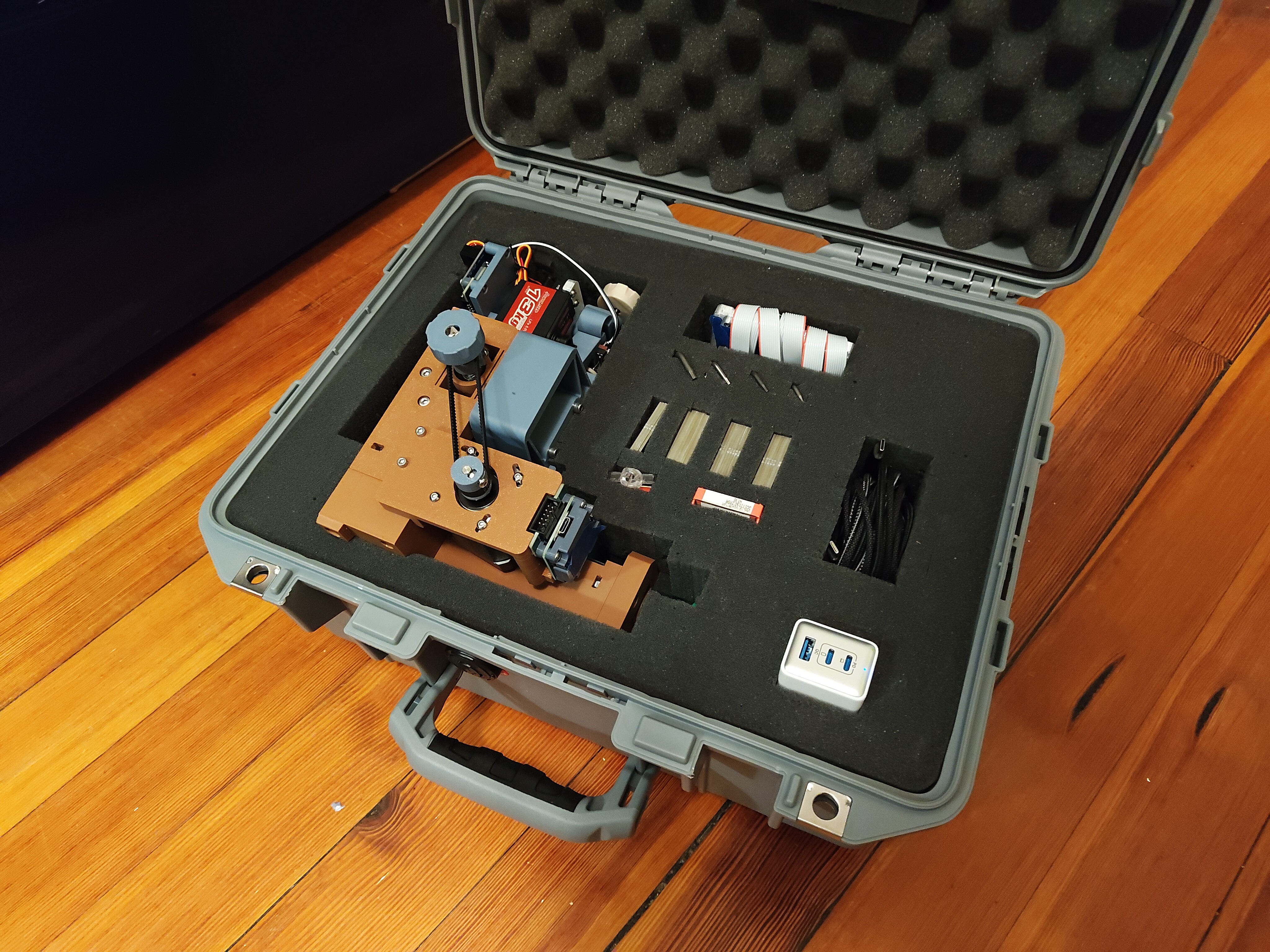
    Other things too: fitting the travel case; generating test patterns using a Python library called drawsvg; Big Wheel Mode to gear down one axes by 4.25 times (since that fit my growing but still sparse belt collection); tests 1-15, some of which looked quite bad; lots of videos of the machine carving FR4; breaking and re-printing a number of parts; and a few new tools, like a diamond scribe and a not great jeweler's saw. But for now, a break.

  • more rhino, the program this time

    zakqwy10/08/2024 at 22:58 0 comments

    I'm feeling progressively better about the mechanical design, and spent some time on a day off piecing it all together in Rhino from the *.stl exports. Here is the machine minus nuts and bolts and belts and controllers, assembled and exploded into the four rigid assemblies:

    Okay, not technically _rigid_ assemblies; what is rigid, after all? There are flexures everywhere, designed in and otherwise! And bearings, and rotating parts, etc. But these four main groups make it easier to discuss machine subsystems.

    In any case, I just bought Rhino for myself and it is fabulous! The program is a different way of thinking about CAD, but after spending a few hours pushing parts around I'm quite happy with its flexibility for creating exploded assembly drawings. And there is so much more! NURBS, and Grasshopper, and all the rest. For now, it's a nice way to compose illustrations; the built-in pen view mode is lovely for complex mechanical things. I've had access to Rhino through various institutions in the past, but only used it sporadically for specific tasks; some recent encouragement pushed me to finally take the plunge and I'm excited to keep playing.

    A few more view captures:
    It might be time to figure out an easy way to add little dashed assembly lines to these exploded views.

  • speed rhino

    zakqwy10/07/2024 at 23:57 0 comments

    Huzzah! I updated two files: circuit_graver_motion.py and run_circuit_graver.py, so that the motion system runs as a simple X/Y Cartesian machine. Relevant parameters:

    actuators = [self._motor_x, self._motor_y, self._servo_z]
    max_accels = [3000, 3000, 1500]
    max_vels = [3000, 3000, 500]
    actuator_currents = [0.5, 0.5, 0.2]
    x_rpu = 1/8
    y_rpu = 1/8
    machine_extents = [30, 30]

    More, probably much more, on controls in the future, I promise. For now, know that I can name and instantiate motors, adjust their maximum rates, and feed them *.svg files. Like this one, the ubiquitous test rhino:

    I used the dial indicator mount and arm to secure a ballpoint gel pen above the stage, and mounted a bit of paper using some tape:

    Rhinos, by and large, turned out quite well at 30 mm horn-to-tail, noting that a pen-up servo would help the render a lot by avoiding the annoying line:

    At quite high accelerations, various rhino parts started to round off, but that isn't an issue; the circuit graver will run far slower than this during carving operations!

    Up next, waking up the Z-axis servo and R-axis stepper! I just ran out of power ribbon cable and IDC connectors, so once I have those I'm hoping for a full 4-axis test, maybe with the Z-axis actually carving a bit of FR4. 

View all 32 project logs

  • 1
    review the CAD design

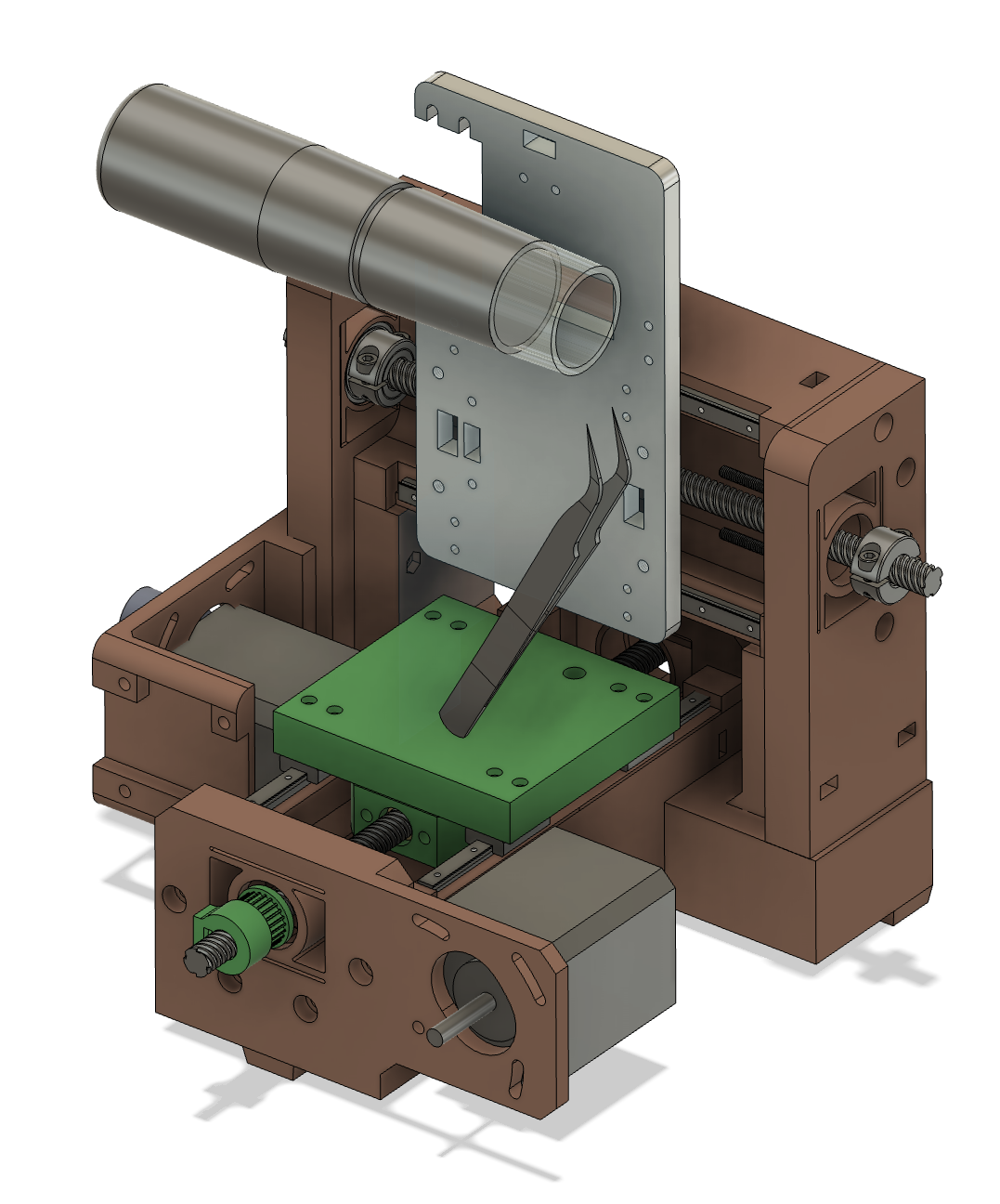
    Download the Fusion360 model and take a bit of time to review the mechanical design of the machine so you can understand how all the parts fit together. The Circuit Graver is color-coded; brown for frame, grey for X/Z axis, ivory for R axis, and green for Y axis. The X and Y axes ride on MGN5 linear guides driven by lead screws and NEMA17 steppers; the Z axis is a flexure, lifted by a servo and pushed down by another flexure; and the R axis is constrained by a pair of 6803 thin-section bearings and driven by a NEMA14 stepper. Most of the parts are held together with M2, M3, and M4 hardware; I tried to keep this to standard assortment sizes (8-20 mm in 4 mm increments), but the machine does require a few longbois.

  • 2
    fabricate the parts

    I printed all of the printable parts in normal PLA at 15% infill and 5 perimeters. Importantly, the print orientation for many things (like the ten flexures used in various parts of the machine) is critical for mechanical performance; this ends up coming at the expense of print production optimization, so get ready for a good amount of support material removal. I ordered the aluminum plate with the requisite tapped holes (see CAD model for which ones) from an online vendor; you could probably mill or waterjet it yourself if you have the fab infrastructure, but some of the locating features are precise enough that I'd avoid bandsawing it.

  • 3
    assembly tests and hand work

    A lot of the parts are tight fits and will need a bit of hand work with a file, sandpaper, and perhaps a deburring tool to fit together well. Go slow and be gentle, and if needed, add offsets to surfaces to suit the quirks of your 3D printer. In particular, the bores for the R-axis bearings need to be cleaned up due to non-optimal print orientation, and the big blind mortise and tenons that fit the frame together needed a bit of work too.

View all 5 instructions

Enjoy this project?

Share

Discussions

100dollarhacker wrote 3 hours ago point

It's nice project. I wonder which maximal resolution you get. In my case it was hard to reach 0.5mm pitch.

Here is my attempt  with more standard tools. https://hackaday.io/project/195654-print-your-own-pcbs-with-lasercncchemicals

  Are you sure? yes | no

Similar Projects

Does this project spark your interest?

Become a member to follow this project and never miss any updates