Close
0%
0%

Not an Ethernet Transceiver

incompatible custom(izable) circuit for sending fast data over twisted pairs

Public Chat
Similar projects worth following
This is not Ethernet, though quite inspired by Fast Ethernet (100Base-TX) and using the same medium (CAT5 or better) and magnetics.
Should provide mostly equivalent performance but does not require all the IEEE 802.xyz hoop-jumping : it could be one-way (just a single pair) and can be implemented in a cheap FPGA or even a Pi pico or something.
Applications are wherever you need to deport devices a few meters or tens of meters with standard cabling, such as sensors, sound, pictures...

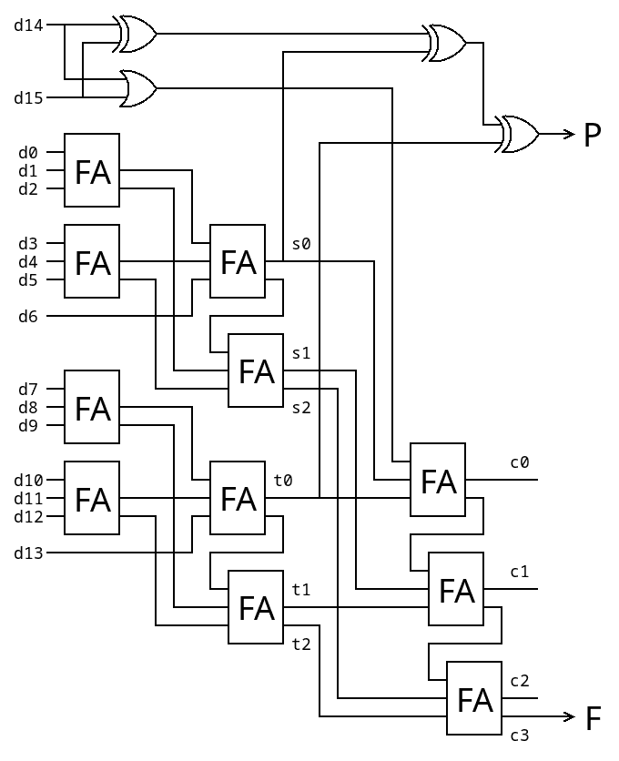
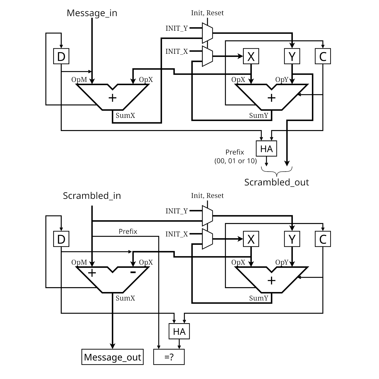
So this is an extension and application of #PEAC Pisano with End-Around Carry algorithm because the PEAC algorithm replaces the scrambler and the 4b/5b table, see

166. Line encoding with PEAC : OK
167. Line encoding with PEAC: it's alive
168. PEACLS error detection (and correction?)
169. TODO: scan

Application is for embedded/custom data transfers over RJ45/Cat5 UTP/STP where the whole TCP/IP stack is not required and a simple FPGA/microcontroller are more than enough.

.

.

 
-o-O-0-O-o-
 

Logs:
1. Let's start.
2. Tinkering with CircuitJS
3. AGC
4. Serial vs Parallel
.
.
.
.

PEACLS_20241025.tgz

16-bit scrambler/descrambler v0

x-compressed-tar - 20.96 kB - 10/26/2024 at 12:35

Download

  • Sender-side droop/wander prevention with MLT-3

    Yann Guidon / YGDES10/29/2024 at 17:14 0 comments

    The MLT-3 encoding has some interesting properties. In particular, it "works" in modulo 4: if the word to be sent has a number of 1s that is 0 mod 4 then we know that the output has gone through a multiple of a full cycle.

    Similarly, if you take the parity of a given word, when it is even, then the output has done a full cycle or a half cycle. This has 2 combined effects :

    1. The parity bit is the least efficient error detection measure, but it is still good to have one.
    2. This parity can be chosen (even) to help reduce droop by forcing 1/4th turn on MLT3 for the next sub-word. The next bits will then be "dephased" by 0 or 1/2 turn.

    Add to this the PEAC scrambler (with carry out), which ensures there is always at least one bit set (and one bit not set) and the parity becomes a way to force the "output phase" (state of MLT3) to either be

    • inverted (+1 becomes -1 and vice versa)
    • remain neutral (0 -> 0)

    So it can be seen as a way to reduce wander. A bit. But it looks like a very interesting dual-purpose system that can both add protection (error detection) and increase signal integrity.

    100Base-TX uses 4b/5b recoding to enhance integrity (by forcing transitions) with a 25% overhead, though unfortunately it gets wiped by the LFSR scrambler. In my early system, a 16-bit word gets 2 more bits (for check & framing), so it the overhead is 12.5% but if that at least 1 transition overall, it's spread over 18 bits... I'm ready to accept a bit more overhead to prevent baseline wander at the source.

    There is already work (see the last log) to make the receiver droop-proof but it easily gets complex... My system does not have a specification for the maximum length or duration of a stable line level so I was preparing for the worst at first. But if I can significantly reduce this risk at the source, even at the cost of some bandwidth, I can simplify the receiver. It's even better if the extra bits serve as checks as well.

     
    -o-0-O-0-o-
     

    Now, how many bits are required ?

    The (leading) pair of carry bits guarantee that at least one bit in the whole word is set. For 16 bits of data, total is 18 bits. The even parity bit provides "phase inversion", bringing the total to 19 bits.

    If we want to ensure that the whole cycle is completed, we need 2 more bits : we get the "RTN" (Return To Neutral) convention that ensures that each word starts and ends with the neutral level at the start of the cycle. There could be 8 combinations:

    • 000
    • 001 010 100
    • 011 110 101
    • 111

    The middle ones have more potential for reorganising the phases such that they are more balanced. But I have found three problems with this :

    • This brings the total to 21 bits which is more than 25% of overhead
    • 21 is a very inconvenient number, though it could be worse if it was prime. 21=3×7 so there is still some wiggle room but it's certainly not binary, not even even.
    • It is not certain that returning to a given MLT-3 phase is desirable, because this could introduce some "bunching" in the power spectrum, at the packet level.

    OTOH using 3 bits per packet could ease other parts of the circuit's design by processing the 18 bits in smaller subsets : 18=6×3 so there could be 3 identical groups of 6 bits to analyse, and local decisions can be individually taken.

    The current choice is to set the total number of bits to 20, 16 data, 2 frame/carry, 2 parities. 20=2×2×5 which is far easier to process, serialise, deserialise and mentally process, and the overhead is again 25% just like 100Base-TX. So now we only have 2 extra bits to balance the wander. Let's make the best of it.

    The consequence is that a full cycle can't be forced. However, it is necessary to keep the parity even, because the next word should start from 0 (one of the two zeroes). Otherwise it's impossible to know if the balance is good or bad, as a simple 90° shift can change the computations and we suppose it's not possible to know the state of the MLT3 FSM in advance.

    For...

    Read more »

  • Serial vs Parallel

    Yann Guidon / YGDES10/28/2024 at 01:27 0 comments

    Historical Ethernet (10Base-T) and Fast Ethernet (100Base-TX) are traditionally working with a serial datastream.

    In 100Base-TX, the data are brought in 4-bit nibbles (25MHz), transformed to 5-bit groups which are serialised and from there, scrambling, NRZI and MLT-3 are done purely serially. It's simple and easy, first because "it uses few gates" (particularly for a pre-Y2K technology) and there was not much to do anyway. Baseline wander didn't even seem to be a concern after all.

    I could implement the PEAC part with a pair of serial adders and shift registers but this would not bring any advantage, particularly when what people desire is speed. There is a thirst of even higher rates and CRCs keep being used, but how do you run one at 25GHz without crazy silicon technologies? Do you really need to use SiGe, BiCMOS, AsGa, InP ?...

    The solution of course is to do as much as possible in the parallel, slower domain, and relegate the serializer to the very last step.

    One scaled-down example is the old Actel ProASIC3 FPGA that is rated for a maximum clock speed of 350MHz but has pins that can reach 700M baud using DDR/dual edging. So one clock cycle transfers 2 bits. And even then, the FPGA fabric can't work at such a speed: the adder would work at 100MHz at best.

    However if the adder provides the 16+2 bits at once, the frequency is reduced to 39MHz. The high-speed design effort is moved to the high-speed parallel-to-serial circuit. This approach is scalable to other FPGA and even ASIC.

    Hopefully it is even possible to preprocess the data to reduce droops.

  • AGC

    Yann Guidon / YGDES10/23/2024 at 20:51 0 comments

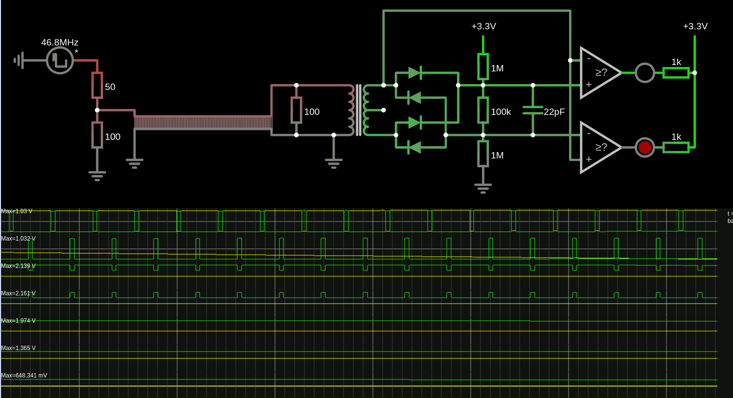
    Trying to adjust the input level... sim here
    As is, it doesn't work as expected yet but it's progressing.

    it's crude but there are some ideas, such as : grounding the center tap capacitively might not be the best solution.

    there are just 2 comparators to detect the +1 and -1 levels, level 0 is in-between.

    The diodes serve 2 purposes : on top of performing envelope detection to set the gain (and charge the capacitor), they also define the margin between the top voltage and the detection level. Since the diode drop increases with current, which also increases with the input signal, the margin is reduced a bit when the signal is low. The diodes are 1N34s (germanium) to lower the drop, yet with some impedance.

    I want to use the transfo in reverse so the line level is 1V and sensed at 2V, giving enough headroom for detection.

    There is a resistive network 1M-100k-1M that "centers" the levels but has enough wiggle room to absorb "droop". The 100k-22pF has a RC time constant for the gain, but the ratio also affects the range of the AGC.

    The topology is not quite right but the main ideas are here : separate the gain from the drift, each has their own time constants.

    • Drift/Droop/wanter has a very short time constant, in the order of the microsecond,
    • gain works on a much longer scale, milliseconds or seconds.

    So 2 capacitors are required...

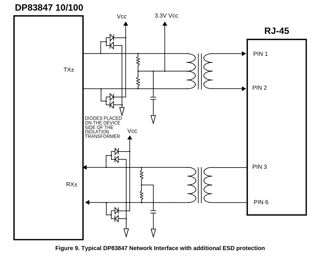
    This is quite different from https://www.ti.com/lit/ds/symlink/dp83847.pdf

    The TX' center tap is directly tied to 3.3V, which is extra weird because the transfo will trigger the ESD protection diodes if one side pulls down... Or you need Vcc = (2×3.3)-0.7=6V ?? Or the swing is shorter: high-side switching gives 5V-3.3V=1.7V but this creates a 3.4V peak-to-peak signal on the line, which is out of spec for Ethernet.

    ... and the RX secondary is somehow floating.

  • Tinkering with CircuitJS

    Yann Guidon / YGDES10/21/2024 at 18:53 0 comments

    Here is the link. I have learned a few important things so far.

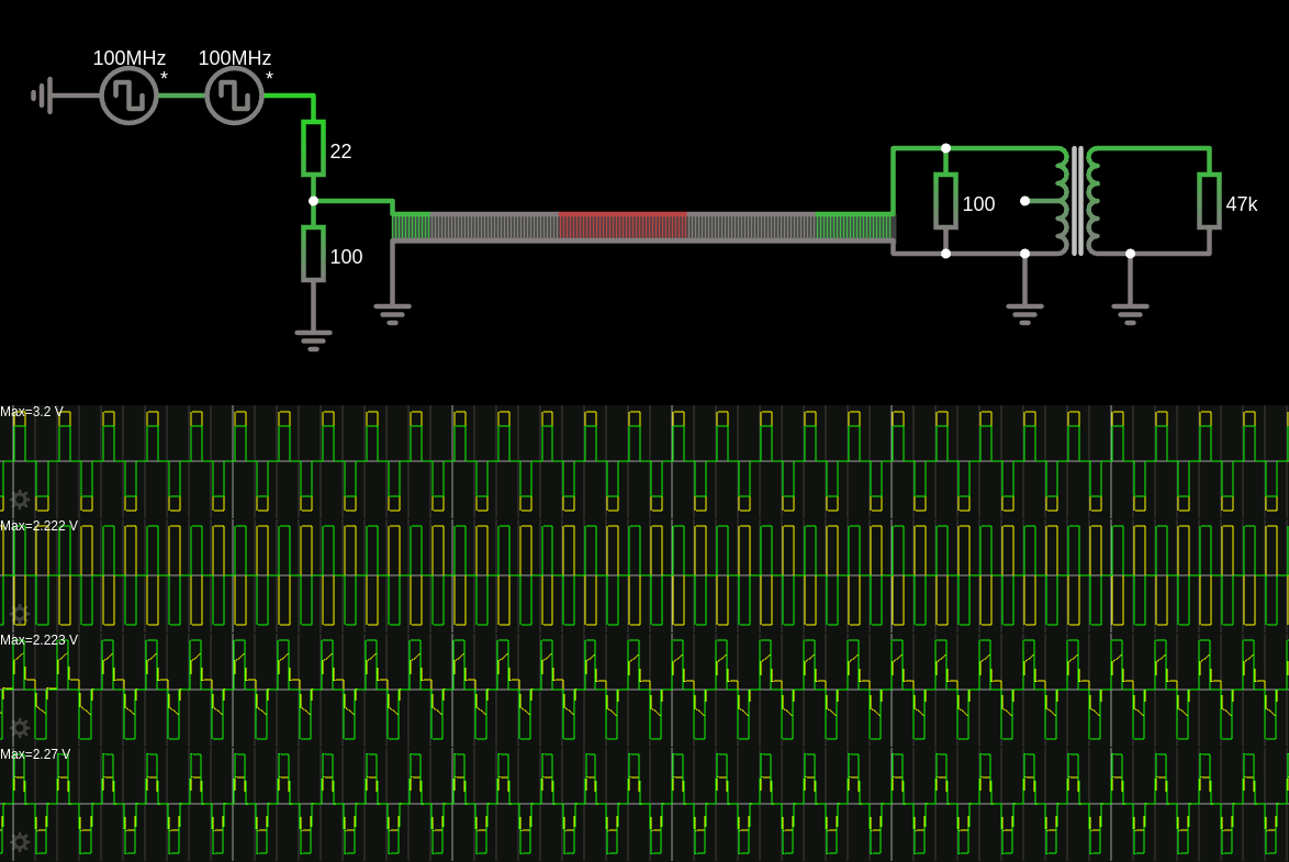
    The big breakthrough was understanding that the transfo introduces distortion when current passes through it because it loads the ferrite with a magnetic field. This is why distortion disappeared when i put the terminator at the end of the transmission line (in front of the transfo) and the transformer acts as a signal isolator, which gets distorted as soon as the sink impedance increases > 47K

    So the link above has no transfo at the source (yeah economy!!!). Otherwise, the current required to drive the magnetics would act like a weird low-pass with some occasional resonances depending on the cable length.

    Source impedance does not look critical in the simulation, but I put a 100 ohm terminator anyway. This acts both as absorption of eventual reflection later in the cable, but also as a signal divider to keep the signal level in spec (around 2 to 2.5V). Correction : line level should be 1V.

    The sense transformer at the end can be used in "amplifier mode" to double the amplitude of the detected signal, but when the line is "pristine", the amplitude reaches -5/+5V levels so an AGC is required. Said AGC can also work for baseline wander compensation : adjusting for gain and offset.

    I'm not sure the idea of introducing "code violations" would work in practice : in a highly-distorting line (with the transfos messing with the signal, reducing the bandwidth dramatically), the break of the sequence heavily disrupts the signal, creating spikes sometimes and then muffling the next symbols. So I have to find a better system to add one optional bit per transmitted word.

    Oh, pictures can be uploaded now !

    But this sim was conducted at relatively low frequency, without inter-symbol interferences due to reflections on the twisted pair. And yes I have set the transfos' inductance to 350µ, as prescribed in the datasheets.

    Of course all of this is simulations with a poorly characterised set of parts. Nothing like SPICE or better : real experiments. But these simulation have shown me a *lot* of effects, including droop ("baseline wander") and I have a better understanding of them now, so I will be less surprised when I encounter them in real life.

    Finally : Falstad's CircuitJS might not be a professional, certified, calibrated, bug-free tool. But it has gotten even better over the years and is incredibly useful to quickly test ideas and check for common effects. The more subtle one require SPICE but it's much less convenient. Thank you Paul!

  • Let's start.

    Yann Guidon / YGDES10/20/2024 at 19:45 0 comments

    So it started maybe two weeks ago when I realised that PEAC w16 could be used as more than a scrambler: Line encoding with PEAC: it's alive. and PEACLS error detection (and correction?)

    There are some drawbacks though, but I have found a better scrambler system using a well-selected gPEAC: TODO: scans

    So instead of using the binary PEAC w16, I use the closest Perfect to a 3x multiple:

    196608 : 196605M 196598P 196594P 

    The ideal modulis is 65536×3=196608, the closest Perfect moduli are 196598 and 196594. You could find your own modulus in gPEAC_scans_1M.tbz if you want to play with a different width.

    The idea is that each data word is scrambled by PEAC, which also provides 2 bits of "pseudo-parity" that can only take the values 00, 01 or 10. The mark 11 is used for control/framing : hence the 3x factor !

    Two benefits :

    • The parity is much less dependent on the MSB of the scrambled data
    • The scrambling is much more thorough

    One concern :

    • the non-binary modulus takes another cycle to compute.

    Another concern : baseline wandering.

    • At the receiver end, some analog tricks could help.
    • At the emitter end, forward correction could be provided by selective negation of the message, but a 3rd header bit would be required.

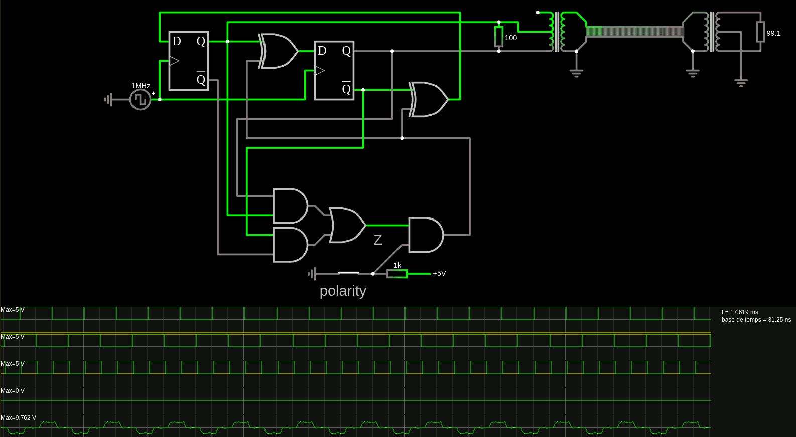
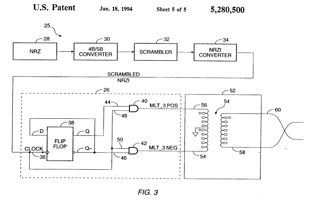
    MLT-3 seems to be the way to go but I find a couple of issues with the classic method. There seems to be a driving conflict because the transformer is driven from both sides with different values, despite the center tap.

    From the "transformer's rule", and as confirmed by simulations, the voltage should be equal on both sides of the tap (it's 1:1) but

    * if out+ drives 1, the AND makes out- drive 0, instead of -1. and vice versa.

    * if either output drives 1, the opposite -1 value gets absorbed by the ESD/clamp/protection diode !

    So in either case, the transformer "shorts" one output in the +1 and -1 cases, meaning that a lot of energy gets channeled to GND.

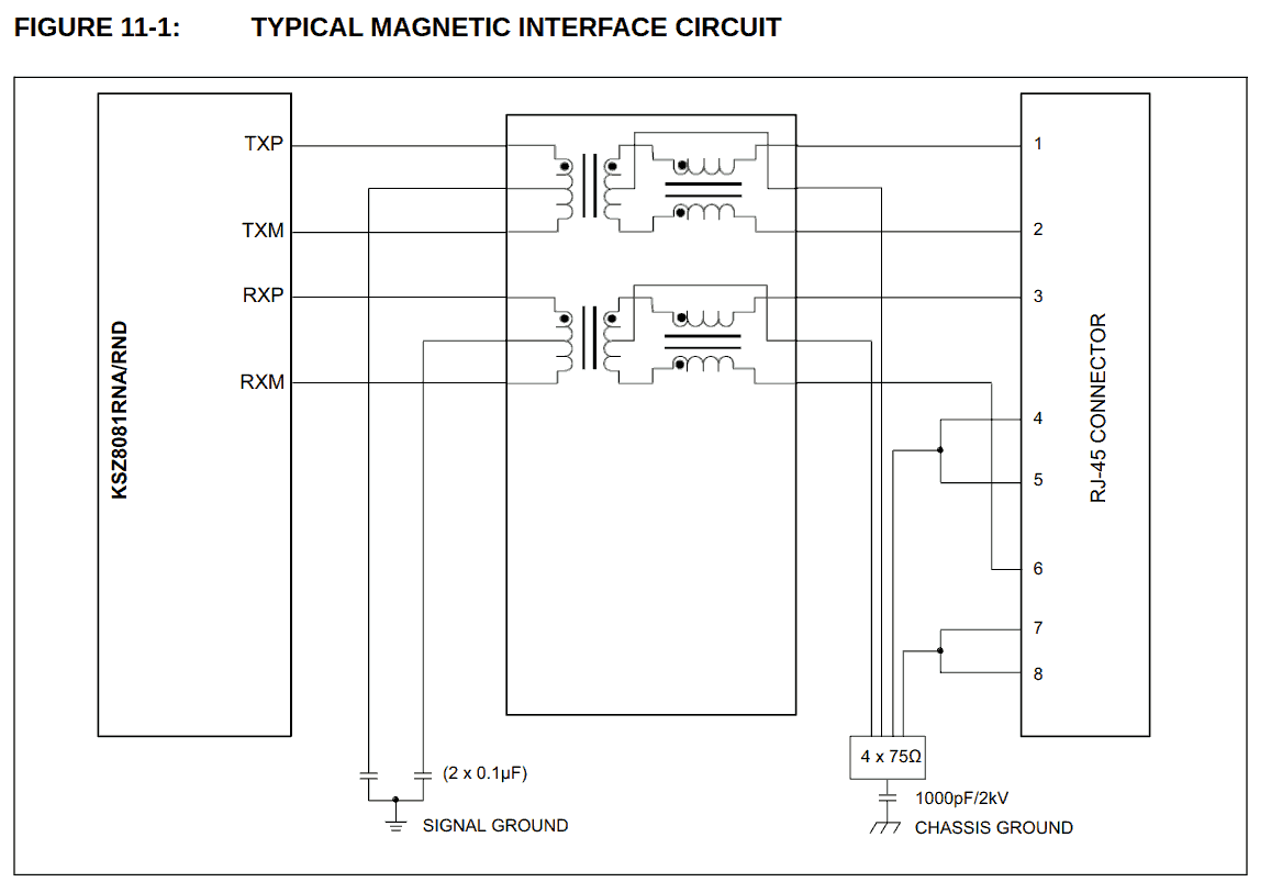
    This datasheet shows that the center tap is capacitively coupled, thus helping a bit but not completely.

    clamp diodes not shown...

    My idea so far is to use a 2-bit quadrature counter, it's very easy to design and the 2 out-of-phase outputs can drive the transformer directly, without conflict, at the cost maybe of some sort of wiggling offset somewhere but... I'll have to test it.

    Oh and since the quadrature code can go in either way, it could also encode the word's polarity/bitflip... I'm trying to explore how it could work on CircuitJS.

View all 5 project logs

Enjoy this project?

Share

Discussions

Yann Guidon / YGDES wrote 10/29/2024 at 02:10 point

The seminal 64b/66b paper : http://www.omnisterra.com/walker/pdfs.talks/dallas.pdf

  Are you sure? yes | no

Yann Guidon / YGDES wrote 10/23/2024 at 18:03 point

at least it's something.
https://www.falstad.com/circuit/circuitjs.html?ctz=CQAgjCBMB0CsCmBaMAGELqUig7LsAHGLAGwol4AsJUAzCLCJfQsmAFADuIJkl4ZHpTRhBKdgDcGg0Wl79Z6KEwp4U65Wi3QOAc2kjBsSgrHp2+kgQJRSPa1AdaLIAJwnbNd-0hPz3VBQbSDtUPk9-EAISH3DohVdIczAcCCtguJiocLRXaFdYdSLiorAkV3ANWiTxbnTs-hi0LH5xACchZocmhqVA9g6exR6WpUKXEe7hEFoUVsj4iIJXGhCaWqiViO8IjeWaMES3X3AjvazDpP3TmoHNg6Prtb71dgAlcDBaA48wL4OwDUlNNaNB6Fp0HAXH9vjM5p9YdUIe0EatQv84fNAsU7jCfgoMZcXiVcYSjnjdpUcQEUOEiYEbESNn94fSybcaQ5nhTnsz2eBsCIzlwBRpuRjeewACaVHBJSByyrhBXy8AAOVolGlSoUOAOuCSKVW6s1IsSjKOOyZ2tQiuwjNpPiCyjAGq1NLpep1N0iYQShsdUGdzIN4C9LN16xFEbDANZws5wVCQWCwejoftlS5aZlfqg01t8umhrd6btitQXMVIarAa5dhDdoLqB80z58L4IhbPpDyoLgclHp8yeV1fYogqVvJ6gtQIwRVojAgiHnKEBsGsxEorkStFoBWdJB0riIZGwOH3Cov5R4x9PtNwlBwwmsN4wO-YAGNRULDYLKTAkBIH8kKkCs3wkGA24kAUBAXpCODsMIECApQjLhtU6EHFEAA6ADOxD4cgsD4diRSkfkmpEAQswbo6KCuLQFEpOQerCN8zAXiEpElOg+HYDxJTFOA+HiMhApoVAFaYVJhq4QRJF4cRgnFMxeAUE0HG0FxilgGCJCwIQE5BJhWAqRoKD8ZZBFCcJYCidGfCMjITluFGAT-vSrnWqIhrfCIGEnEayhSvAABmACGACuAA2AAuiAxfAuZKNoa7jrw4D+bJWUnCqIXhdF8WJcl4CpZC6UdP8AU-M6wUiEUuLZflUHOvlDWvAEL45a1WHmB8vWxuA3V-HOTBoKC4KpVCHmSdy-6DlSs5LW5vozqtqE2FszLeS5c1OOwAD2URlWgwg7uAmCMPO65KFcMxHcNp3jRdekhBVa6kO9zRPbQj1LsCDEVDA13QMUrh6l913KIwf3HVgz3ncDcAfeoEMGbw0PykkcN0IjQMMKjDGQ5jd147jdKAxdINE+jUNk+EuOUADZ0E29oPgyT33KMzD20DYOAgAAYhAaCsBUsBg7ZQllIggvICAAAi8AxRFACe7D8yAgsi2V70siACsAJIALYAA7JRFAB2n7wJrjLCxA9BkWK0uGxAQttPAACOUXwDbGtax7EDQ4E7tK1FcVq-hADCaufkl9tlbrSSINgQbh4rMf4QA8mFYV4fAcVJ8H5WMArACyEUAB74QAaod8URbodtAA

  Are you sure? yes | no

Ken Yap wrote 10/21/2024 at 22:04 point

Ethernet does not imply TCP/IP. IP is just one of the protocols that can be transported on Ethernet. Historically there were other protocol families such as Novell's IPX which could be carried simultaneously with IP. However IP is now the standard. They all use the now standardised Ethernet frame which is the data link layer.

Your project establishes a different data link layer so cannot be used with standard Ethernet hardware except the cables and the sockets. But you knew that of course.

I've toyed with the idea of using Ethernet cables and sockets for carrying power and signals over up to a few metres purely as a local hack because I have lots of cables. Mainly to counter the proliferation of wall wart power supplies. I would have to ensure those sockets are never used with normal Ethernet connections.  PoE would be a standard way to get what I want with more flexibility but more hardware complexity. But truth be told, wall warts and WiFi or Bluetooth are probably preferable to Ethernet cables all over the place.

  Are you sure? yes | no

Yann Guidon / YGDES wrote 10/21/2024 at 22:23 point

Hi @Ken Yap !

I remember IPX, programming it in ASM around 1997... and the ISA Ethernet cards using coax, the T and terminators :-D

> But you knew that of course.

I do.

> purely as a local hack

Well, in some cases, I need to go beyond the local hack.

So far, I have implemented TCP/IP boards such as #WizYasep but they are too often overkill for the clients' needs. Hence this project, where I also explore alternative novel data processing techniques.

And in many of my applications, radio links can't be selected.

  Are you sure? yes | no

Ken Yap wrote 10/21/2024 at 22:54 point

Fortunately I have only myself to entertain these days. 🙂

  Are you sure? yes | no

Yann Guidon / YGDES wrote 10/22/2024 at 12:59 point

@Ken Yap 

and Hackaday helps you :-)

  Are you sure? yes | no

Ken Yap wrote 10/22/2024 at 13:13 point

There are other entertainments awaiting when I have exhausted/tire of this one. 😊

PS: Tagging the recipient is redundant when the reply is below theirs and just generates annoying email traffic.

  Are you sure? yes | no

Yann Guidon / YGDES wrote 10/22/2024 at 13:16 point

I didn't get a notification..

Let's see if it works this time.

  Are you sure? yes | no

Ken Yap wrote 10/22/2024 at 13:22 point

You certainly generated two emails to me with your first reply. 👿

  Are you sure? yes | no

Yann Guidon / YGDES wrote 10/21/2024 at 20:44 point

https://www.ti.com/lit/an/snla266a/snla266a.pdf

https://ww1.microchip.com/downloads/en/AppNotes/AN2686-Ethernet-Compliance-Test-10BASET-100BASETX-1000BASET.pdf

https://download.tek.com/document/61W_17381_3.pdf

https://cdn.teledynelecroy.com/files/appnotes/100base-t1-ethernet.pdf

https://pdfserv.maximintegrated.com/en/an/AN1738.pdf

https://bitsavers.org/components/national/_dataBooks/1995_National_Ethernet_Databook.pdf

https://ibis.org/summits/feb19/dmitriev-zdorov.pdf

 ...

  Are you sure? yes | no

Yann Guidon / YGDES wrote 10/21/2024 at 07:15 point

https://www.falstad.com/circuit/circuitjs.html?ctz=CQAgjCBMB0CsCmBaMAGc0yRQDgCwGZZZJdsUUA2ATn3AHYRYQDGkwwAoAdxApPApoKuNGEEgUHAG7MqFAWljixaNJHD4UVcjvTzVEuBwDms+SuZkFEiRzFVwYfPMhLwKOutf7DOwuF8dXGo8EkhBYUg6WBRcEEQUaB1KFDBtKlg6XG1hXDA3BKSdQTStTOzKXDz-RKoqE0dnKE9Gl2xsG0lTCnaoNx6OyF7VBtQW73dx4dsediaJuZcWyVmncyp1djxwDZmQOq9+A531STA6CAGoI93IfjQqaAzkl50wJAdUNHxT7l5eu5xYRqe4cABOvBEUF6wOucVE5HBkNE4lhgJsdwaaJhUM08L2xwWKH4ExW7hJbjGXjcZNQ-DSmw8m12ZOODPJcXZkghdM5u15fR8XyRWz5mzA21JzDoOj+i0FjklNOkjGUqPp4jU7leomgQrgMroch+FCNpDk+iMAHsbBA0CI6oxfEwtd8ODb2AF7VoHDAXUlXBjHCB8O76F7mD6oHBAuQqHQKEpA1rziGwx07ZHHX7Y1oE0mXVAQB1QzaGJmHQ5EskE5AaFRcLB8Jh-cl44m+IX1AxQ-gM2gAGKZhCIBywIo6l7vRAMZAgAAi8AANgBDACeHD77hAQ4CgfYaDnAEkALYAB3gABMVwA7ADG8E3GZ3EFoX2SUEn8QgA7B8AAjgArvA94bludwvkW3zfguADCAA6ADOADyABmqGIfAAAuHBAA

  Are you sure? yes | no

Yann Guidon / YGDES wrote 10/21/2024 at 05:35 point

https://www.falstad.com/circuit/circuitjs.html?ctz=CQAgjCBMB0CsCmBaMAGK0wA4DMrZgBYsA2SFTA48AdhFhAOzqTDACgB3OggqSX2MTSR+IFGwBuDTMNGwefXsPApVa1eGhUwWsWLhsA5tNm9KvEUrFswxAJzhbmKIMcoLrtCmhrs9CN7qdtTBYNTu4dTYKIQQiIExuHaYItRgkILEBJBRIIiYGLj4pHbYWek4SGT6dnZGjsTOOZANTZjOXvWNTa7dUO164sas7i7aqBYDnVysjWOtUNQt4jNO4HYt6bbry5wgtS2WKuSK1mEQfUcHp2h20Haw6k9qYEgOqGjYu1zXGdqqPSoKxAl1EWVM1gATiCCMIBuCbsc2NDBBCEUc0GBYF1Yf1nAjolZgR9ASpXM1rDMUOSlm4PEC9iTTngqGQOozqayTiMLKJxNCWVBuZzFsskQLINswBtwJLWZ4GOFVIy1n9Zds1eIAPZ6AIMFC1Oj6PVi7BsHXpcB6WGGmD0QL2qCykBmi3OPU2hx2-TUvSbZyukDu60Ghz2nyqaWwXAZP1Bl3mkC0D2hn1qaglbB2AjR9LhoIZwSx5S0M3Yd1oABieoQiDDEeez1eiFoyBAABF4AAbACGAE82OWVCBq1bYyM8hAAJIAWwADvAACY9gB2AGN4IPg6OmB91MdnpOR5D4ABHACu8HXA6AA only one transfo, then.

  Are you sure? yes | no

Similar Projects

Does this project spark your interest?

Become a member to follow this project and never miss any updates