Close
0%
0%

OSUG: Open-Source Underwater Glider

A versatile autonomous environmental drone using a buoyancy engine

Similar projects worth following
There has been a breakthrough with low cost autonomous drones and as this capability has matured a wide range of hobby and commercial applications have developed. There are no affordable extended duration underwater exploration platforms and this project aims to address this need.

Utilising commodity hardware, 3D printed parts and an open-source autopilot, I aim to produce a low cost and versatile underwater glider capable of extended missions of up to weeks at a time. I hope that by having this platform available, it would reduce the cost of underwater projects for all, from hobbyists, amateur scientists to seafood farmers.

Contents

Interesting logs

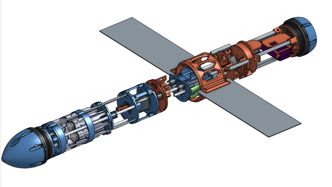
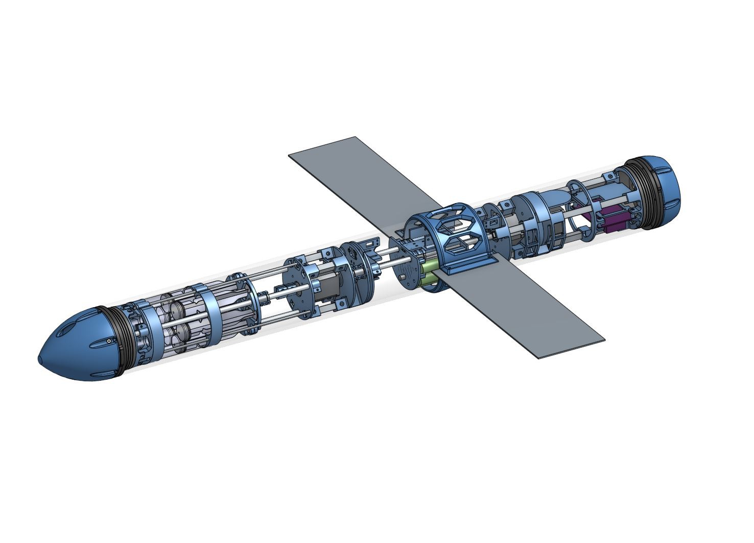
The CAD model

The model is viewable on the Onshape online platform here (requires webGL)


Video


Why a glider?

Traditional unmanned underwater vehicles depend upon active propulsion, limiting their range and runtime, making them unsuitable for long duration monitoring missions. Underwater gliders use a buoyancy engine to change the mass of the glider, allowing them to ascend and descend through the water. With power only being used to power the engine intermittently, gliders can typically run for weeks or months without recharge, making them ideal for environmental monitoring. Yet there are few commercial solutions available (and those that are available are very expensive) and even fewer hobbyist projects exist.

As underwater gliders travel slowly through the water, they disturb the surrounding water very little, allowing for accurate and reliable data recording. Underwater gliders are normally AUVs (Autonomous Underwater Vehicles) and can run a pre-determined route without requiring human interaction. Their low speeds and autonomy, combined with long battery life, make underwater gliders ideal for long duration, environmental monitoring missions, capable of recording dissolved gas levels, pH, temperature and optical sensing (for oceanic surveying and sealife recording).

This glider is open-source, with 3D printed components combined with readily available hardware, allowing it to be assembled for a low cost. Given the openness of the project, the project could be forked to produce alternative designs suited to particular scenarios. For instance; changing the tubing to aluminium to become a deep sea glider or using a unique sensor array for specialised applications.

I am looking to use the open-source Mission Planner combined with the Pixhawk autopilot platform, allowing the glider to be controlled using a standardised interface.


Example use case

With increasing interest in product transparency and traceability, environmental monitoring is becoming increasingly important; a kelp farmer could use the glider to monitor water conditions (temperature/pH/nutrition levels/pollution) during a season of growth and push the measurements to a blockchain. The kelp/seafood could be packaged with a QR code, which would direct you to a web frontend, presenting the conditions during the season of growth. The use of the blockchain and data insurance for measurement storage would remove the chance of measurement tampering, so the consumer would know both the conditions that their food grew in and exactly what they’re eating.

Above: A block diagram outlining the how the glider could be used for product traceability

How?

For the glider to move, the buoyancy engine takes in water and increases the density of the glider. When the density of the glider becomes greater than that of the surrounding water, the glider descends. The wings of the glider ensure that the glider goes forwards and the angle of attack can be altered to cause different glider characteristics. When at the bottom of the descent, the buoyancy engine will expel the contained water, making the glider more buoyant, causing it to ascend, moving forward again.

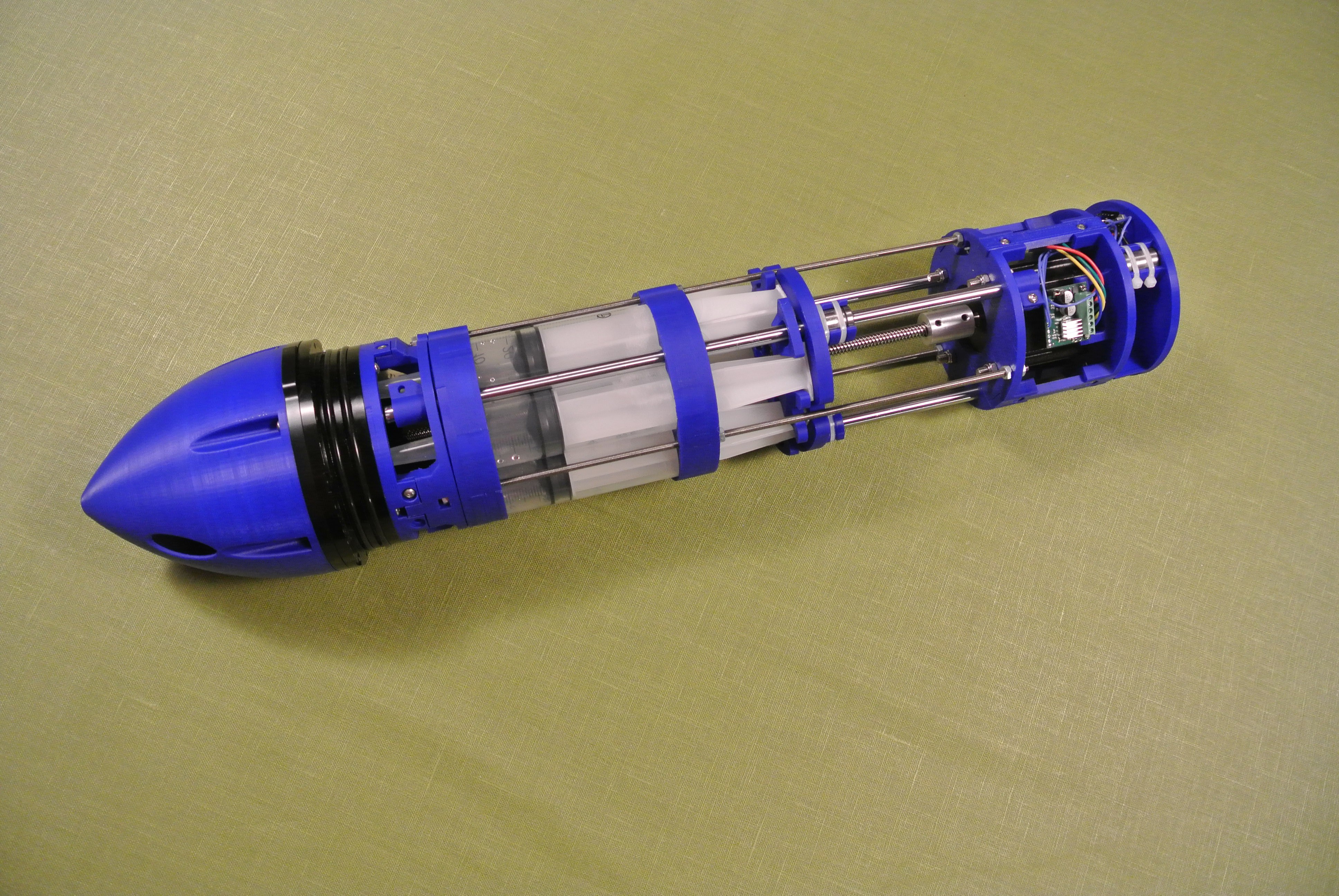
The buoyancy engine that I have designed uses an acme rod to move the ends of the syringes when rotated by a stepper motor, causing the plungers to take in water. When water is taken in, the volume of the glider remains constant, but the overall mass increases, therefore the overall density of the glider increases and the glider becomes less buoyant.At the centre of the glider will be...

Read more »

GNU GENERAL PUBLIC LICENSE V3.pdf

This project uses the GPL v3 license​ for all software related to the glider.

Adobe Portable Document Format - 78.20 kB - 10/21/2017 at 10:31

Preview

demo.ino

Arduino demo program for gliding forwards by descending and ascending

ino - 2.79 kB - 10/14/2017 at 23:02

Download

Calibration.ino

Arduino calibration program for calibrating the buoyancy trim of the glider

ino - 2.51 kB - 10/14/2017 at 23:02

Download

End_caps.pdf

Endcap drilling guide

Adobe Portable Document Format - 5.63 kB - 10/10/2017 at 22:58

Preview

Planetary_gearbox.scad

scad - 8.97 kB - 10/14/2017 at 22:30

Download

View all 54 files

  • 1 × Printed parts
  • 1 × Blue Robotics 4" tubing 1000mm The main tubing
  • 1 × MPU6050 Gyroscope/accelerometer
  • 3 × A4988 Stepper motor driver Stepper motor drivers
  • 6 × 18650 Protected cells Litium-ion batteries

View all 73 components

  • Pogo pin board replacement

    alexw03/07/2018 at 19:56 0 comments

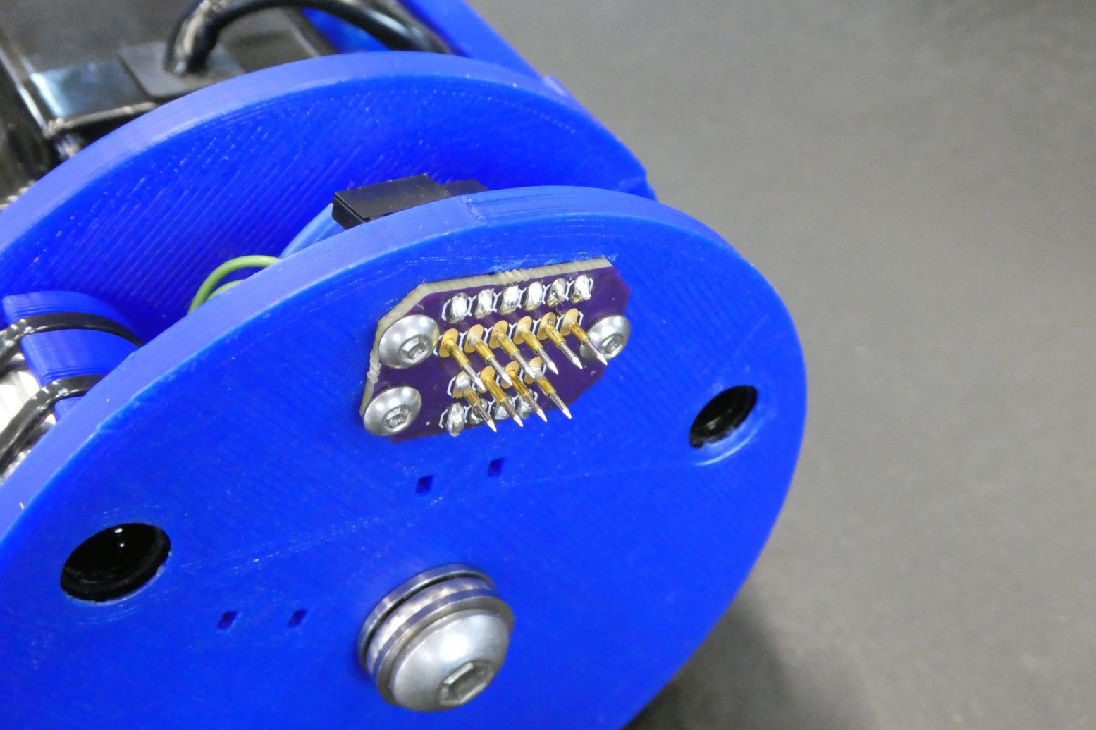
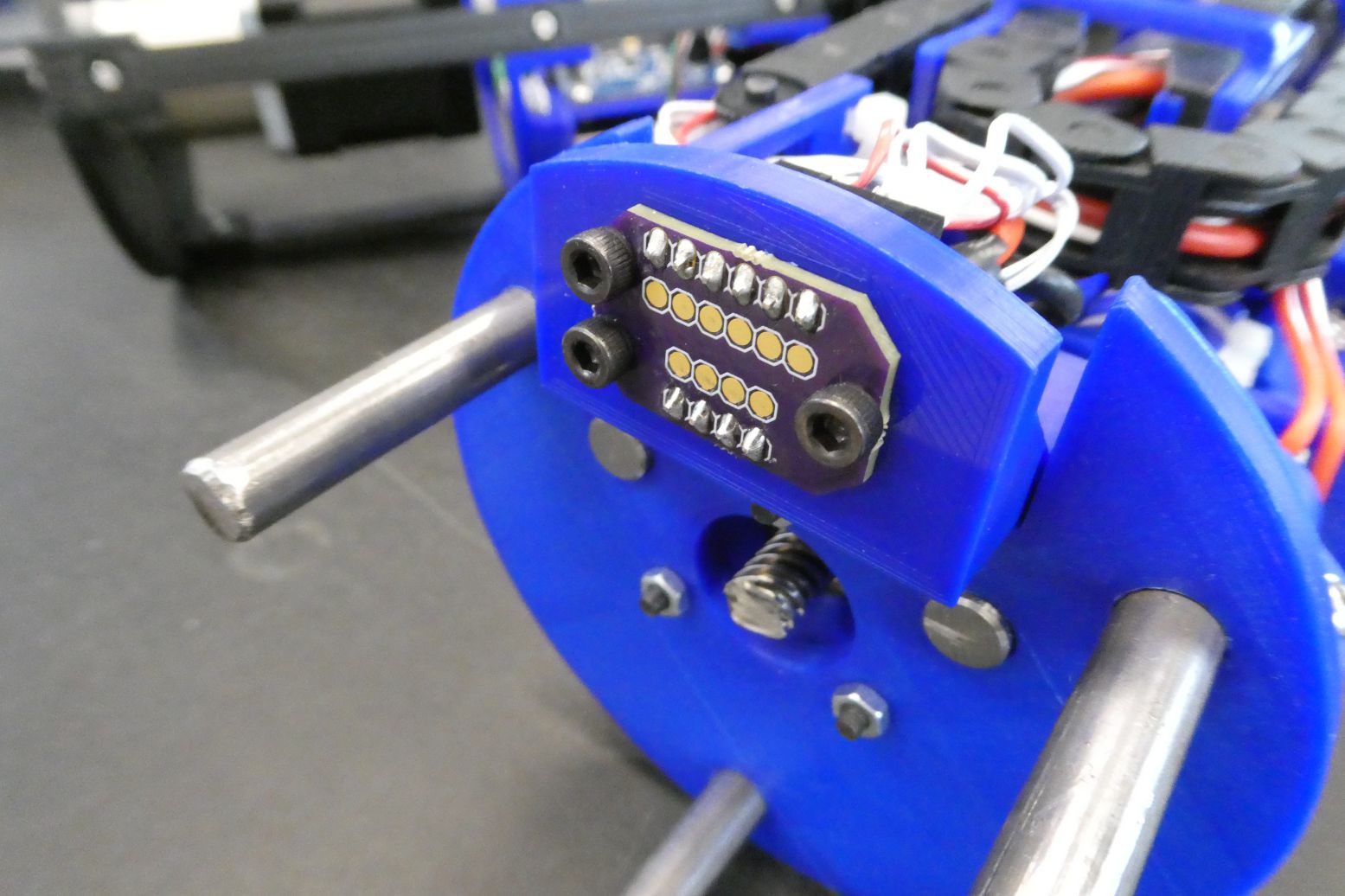
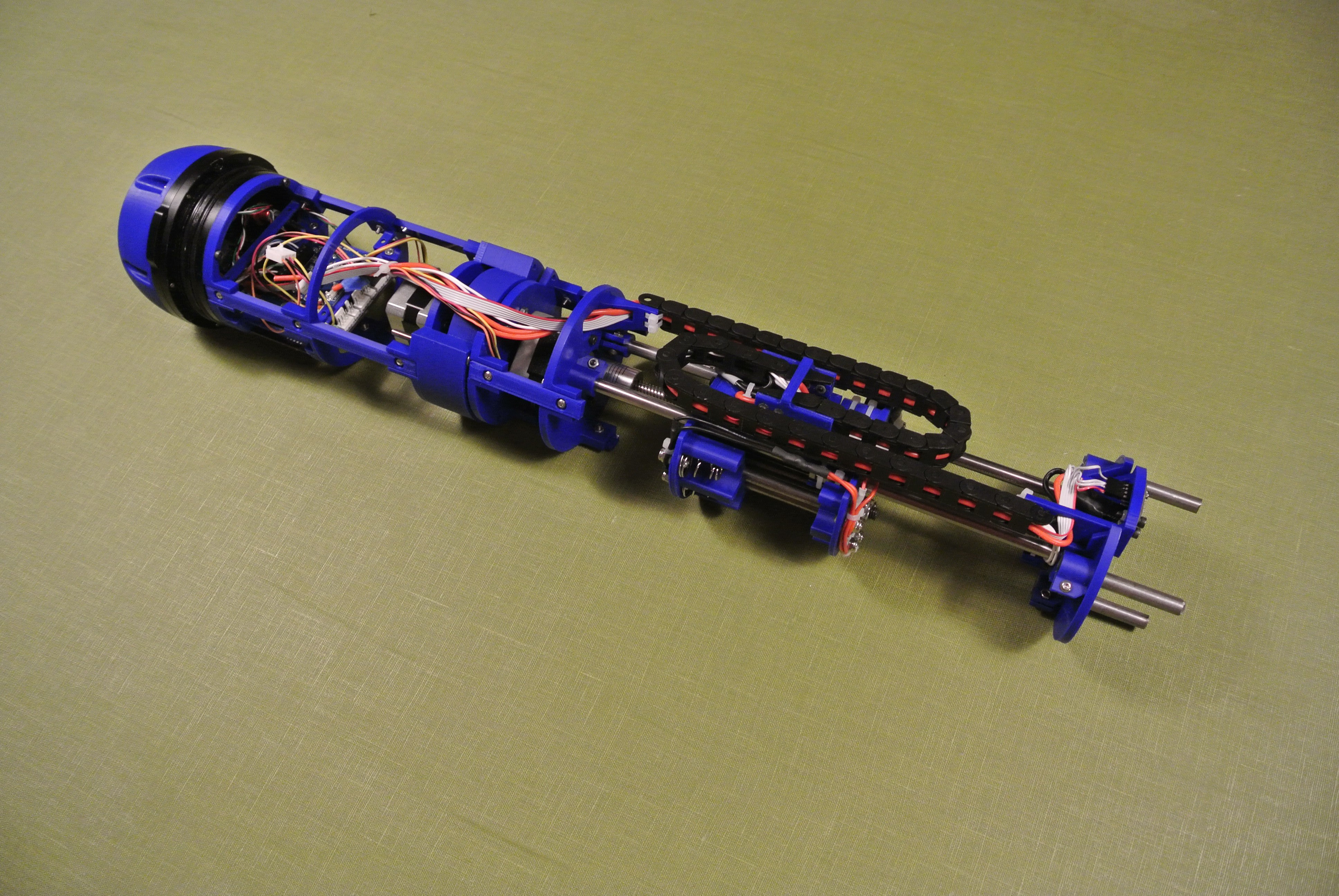
    The glider has 2 physical sections internally, the first is the buoyancy engine section and the second is the control boards and the pitch mechanism. The current design (below) uses pogo pins and a pair of boards to electrically connect the two sections, however this has two main downsides.

    The first problem with the pogo pins is that they use a spring mechanism in order to ensure a reliable connection, this causes the two sections of the glider to be pushed apart when the glider is assembled, which reduces the reliability of the connection. The other issue with this connection type is that the travel of the pogo connectors is only a few mm, which means that the rest of the glider must be aligned to within a couple of mm - the current solution to this is the sliding mounting bracket of the pogo connector PCB.

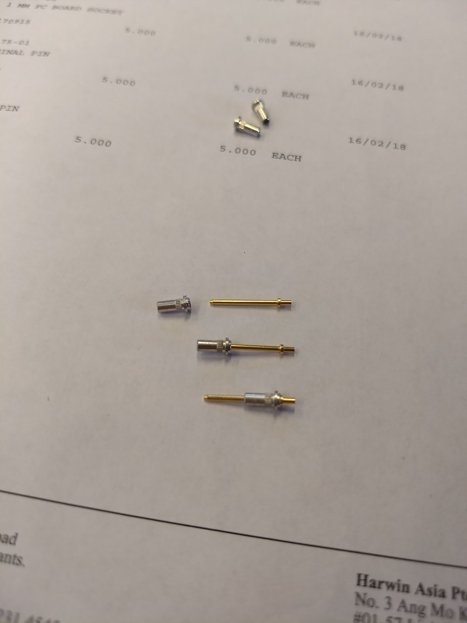
    With this in mind, the ideal connection would be one that does not have a spring contact and has ~10mm of travel. After having a look I was able to find the PCB contacts from Harwin that do exactly that, namely the H3169 and H2170 connectors.

    I ordered some sample connectors and they came through and were a perfect match for what I wanted, so I went ahead and purchased ~20 more connectors and designed some boards in Eagle for the two sides of the connector. Below is an image showing that the connectors in varying positions, all with solid electrical connections.

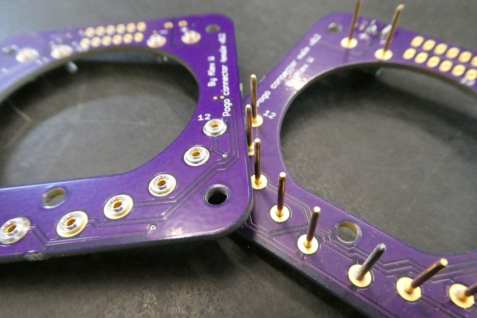
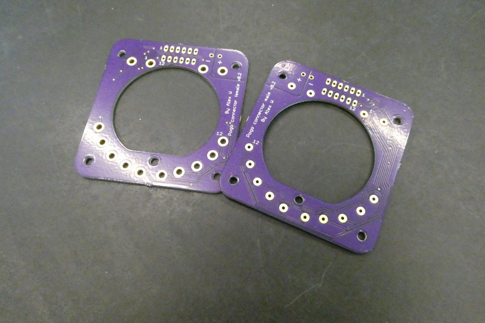
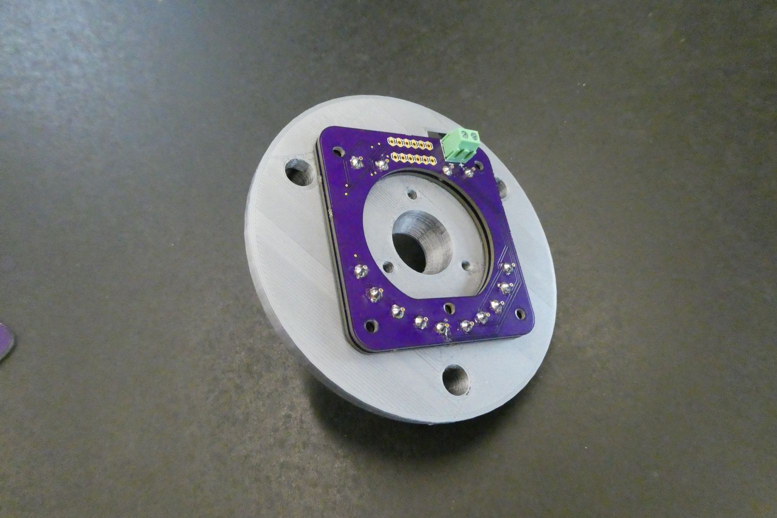
    I designed some updated boards for the ordered the PCBs through OSHpark and a massive shoutout to Drew (@pdp7) for providing great customer service and making sure I got my boards within a week. Below are some images of the boards and what they look like with the PCB connectors attached.

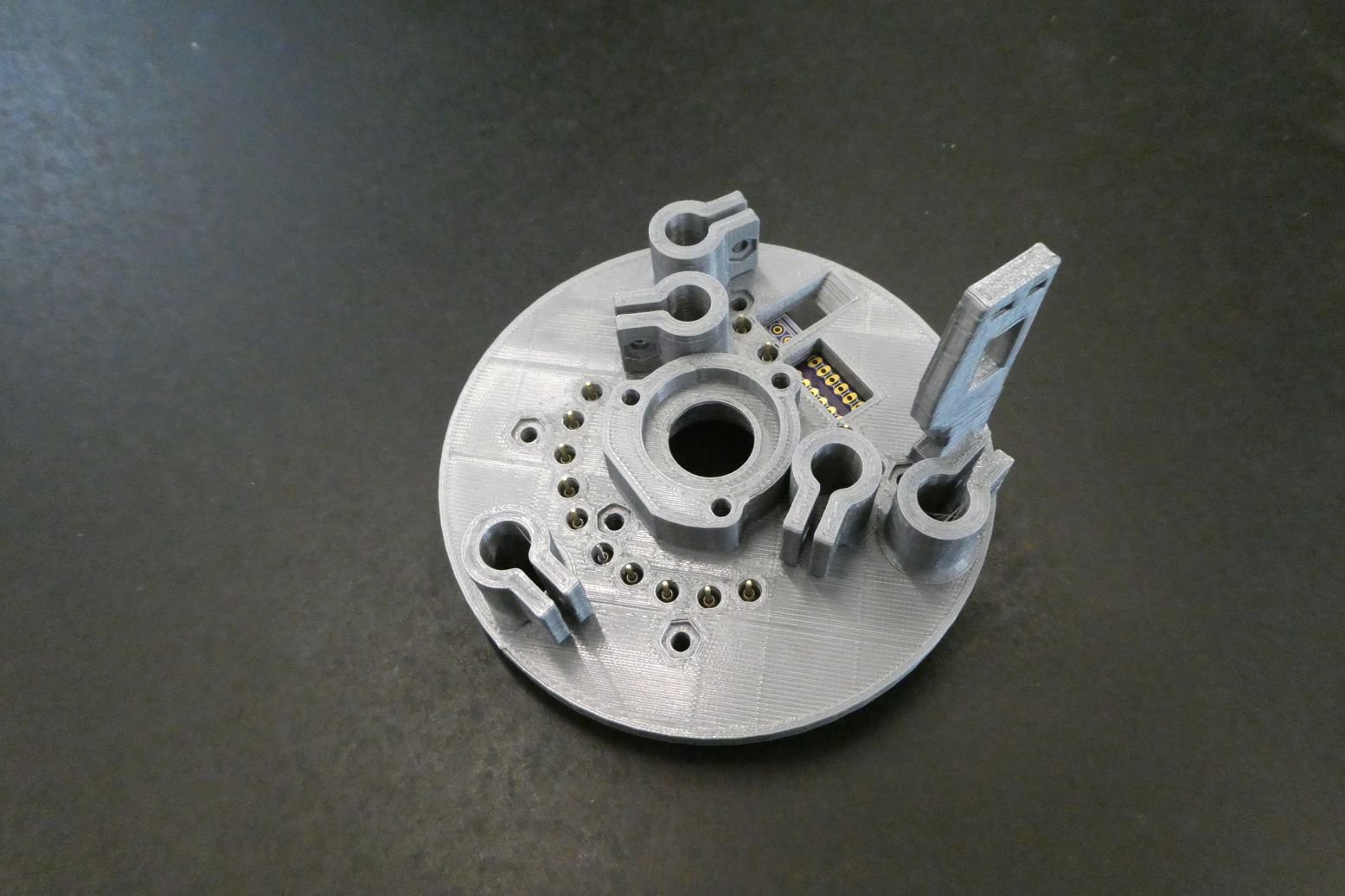
    This new configuration also more equally distributes the force of the contacts through the plate, as opposed to on the small section at the top. I designed and printed an updated PCB mounting bracket and you can see how the board fits in-between the alignment rods:

    Although using Onshape was an interesting experience, I am now transitioning to Solidworks for the design of the glider, but understanding that not everyone has access to Solidworks, I will still be providing the STL files so anyone can download and print the parts. The PCB files are also in the Dropbox development folder.

  • Assembled control board and backend update

    alexw01/26/2018 at 06:16 0 comments

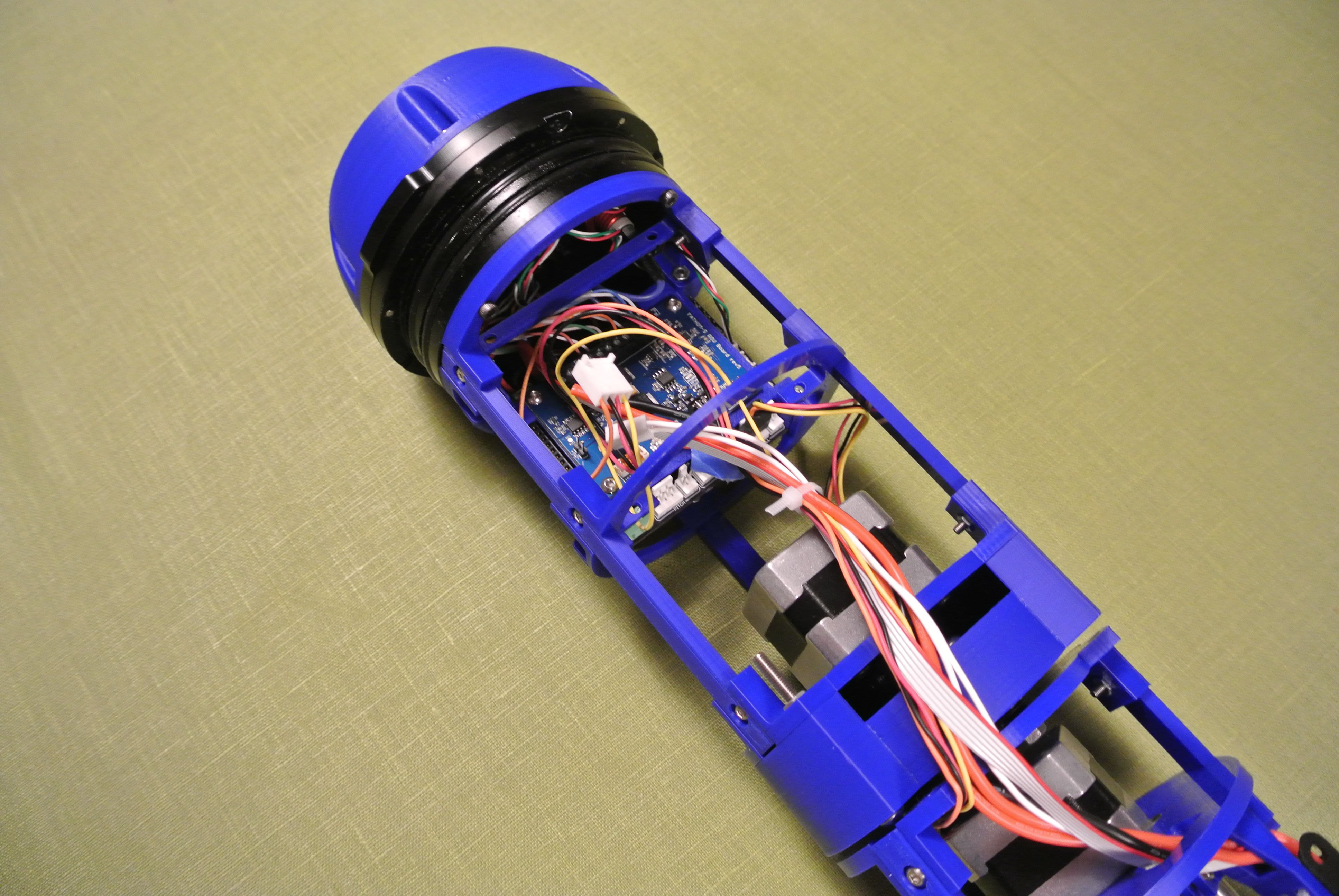
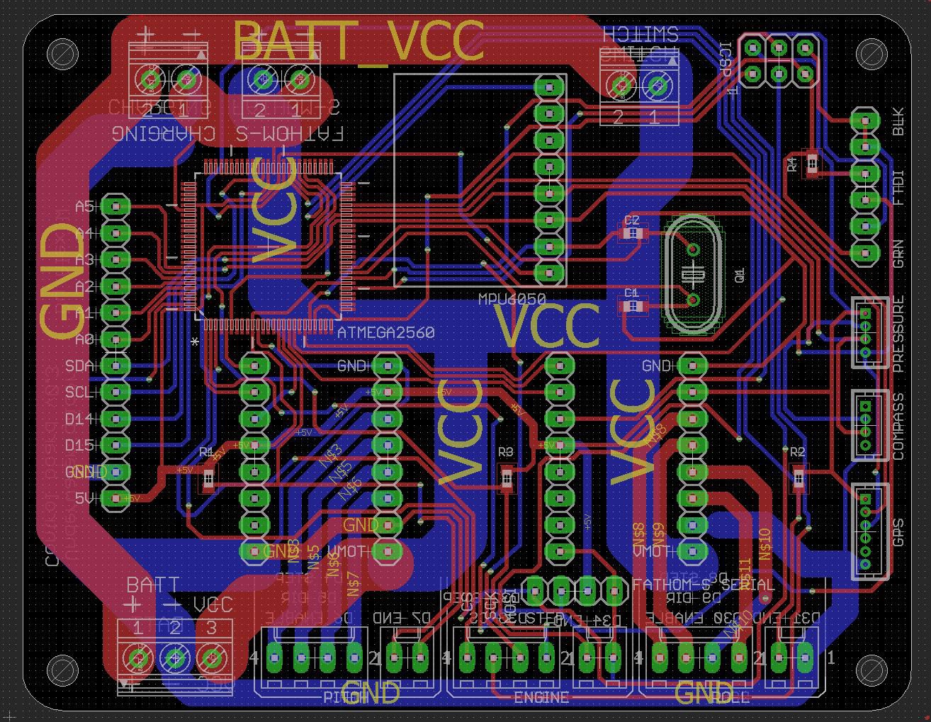
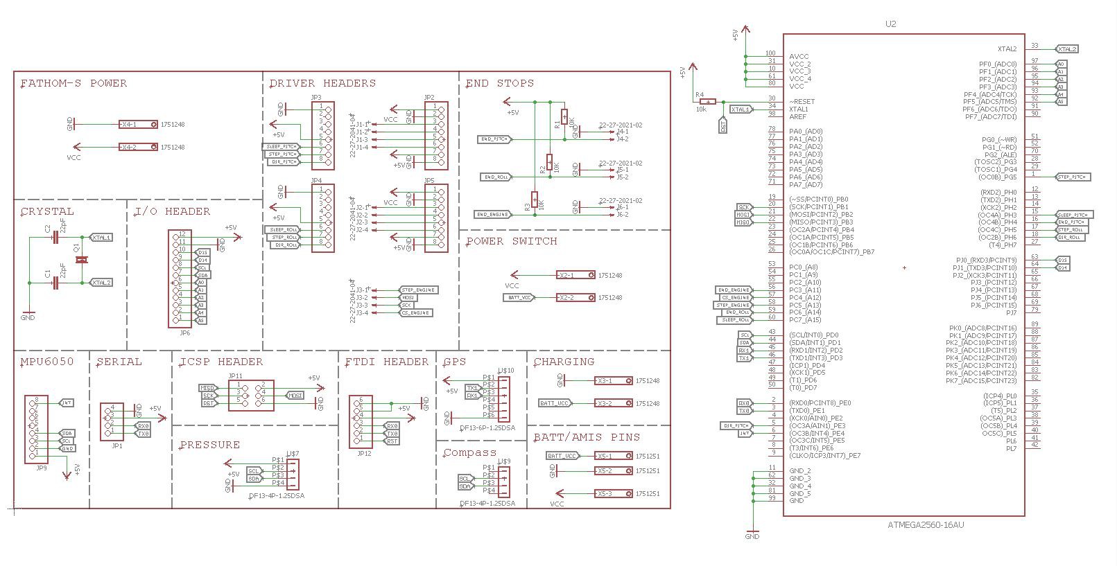
    The backend has been redesigned to be much more open for the new control board, and all the connectors are much more accessible. Also the control board has been lowered to allow for the integration of the Pixhawk 2.1 autopilot (the Cube took up too much vertical space previously). Most of the update to V3.1 has been completed but wiring still has to be completed. 

    The planetary gearbox has also been thickened to reduce play, but the latest version printed with too much of a bond between gears so I plan on reprinting this on a FORM 2 printer as this will be able to achieve a much better tolerance. I also changed the position of wiring past the planetary gearbox; previously the wiring ran on the side of the gearbox, which limited rotation, however the wiring now passes over the top of the gearbox and rotatory limits are symmetrical.

    Nothing noteworthy has occurred to the mass assembly, apart from the general thickening of printed pieces.

    The exterior components have been reprinted in 100% PLA and are not resin coated (The prints previously failed with 100% infill and let in water so had to be coated). However PLA still absorbed water – reports are a ~5% weight increase over a period of 30 days submerged, so I will look at printing the exterior components from PET-G.

  • Buoyancy engine update

    alexw01/26/2018 at 06:07 0 comments

    The last few weeks have been completely hectic and I have been unable to find time to document progress. I’m currently on a flight from London to Los Angeles to take up a residency at Supplygrame’s DesignLab to work on the glider, so I thought it would be a good time to do a few updates on the glider’s progress. I’ll split the update into two shorter sections, one for the buoyancy engine and another for the backend.

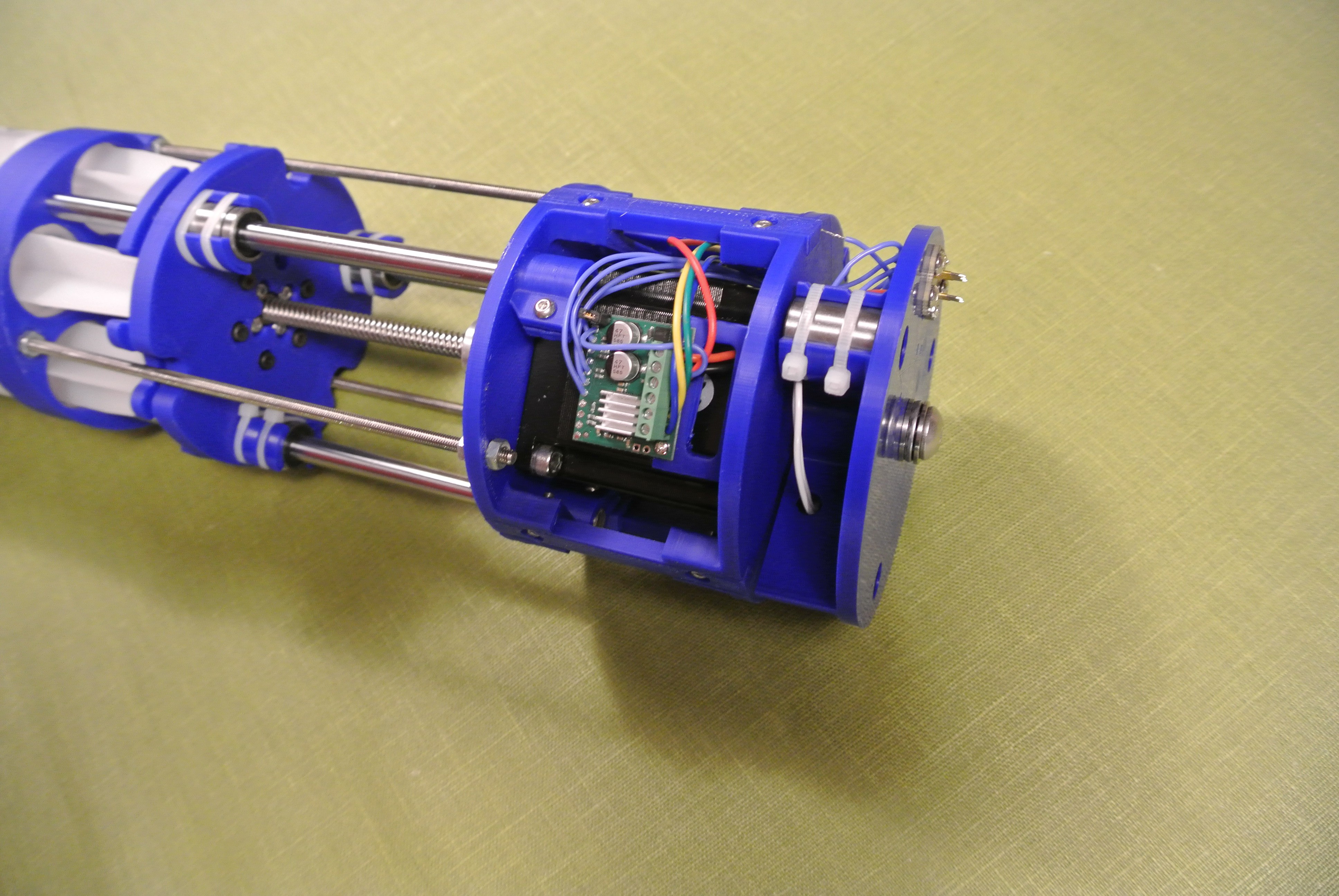
    Throughout most of the upgrade from version 3 to 3.1 I have been thickening components to improve structural strength, notably in the buoyancy engine. Below are two images of the engine, before and after the upgrade.

    Also note that the stepper motor has been upgraded from a NEMA 17 to a NEMA 23 motor, which runs at an equal power but has far greater torque. I have also moved the buoyancy engine stepper motor driver from the control board to mounted at the front of the glider, so that communication wires can be of a lower gauge and greater power can be delivered to the engine’s stepper motor. I have also upgraded the stepper motor from a A4988 to an AMIS-30543, as stated in my previous update. This allows for SPI communication to control the stepper motor more accurately and alter coil current on the fly.

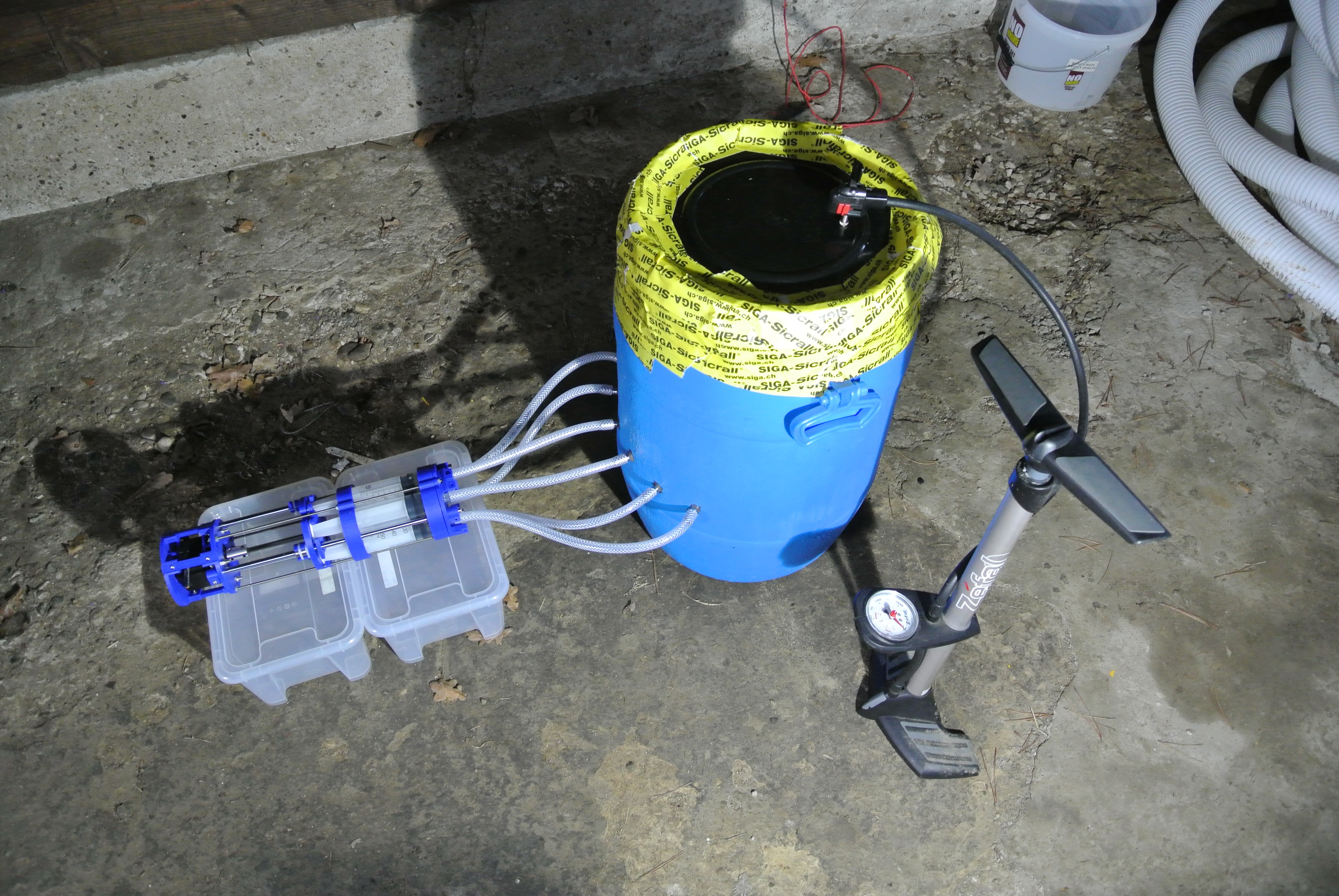
    All of the glider’s components in contact with water are rated to a depth of at least 100m, apart from the buoyancy engine. Therefore a depth rating of the glider can be determined by pressure testing the buoyancy engine (unless it can perform to a depth greater than 100m, which is almost guaranteed to be false). Hence I meant to test the buoyancy engine, however I was time constrained and air is a harder medium to deal with than I initially thought. Regardless, I’ll outline briefly the attempted testing method for anyone is interested.

    The idea was to connect the engine to a water barrel using the same tubing and connectors that are within the glider, to try and accurately represent the system used. The barrel then had a pump attached (it was a car tyre pump until a lack of suitable power source became an issue) to pressurise the water within the container until the engine failed. The engine would constantly pump as I believed the syringe seals were more likely to fail when moving. Unfortunately the seal at the top of the container wasn’t sufficient and even after multiple layers of airtight tape there were small leaks that would reduce pressure within the container. I was going to switch to using a silicone sealant to properly air-tighten the container but I ran out of time.

  • Control board v0.3 designed and ordered

    alexw01/10/2018 at 19:34 0 comments

    Over the last few days I've updated the design for the control board, with two notable improvements. The first is the hook-up of the "enable" pins of the stepper motor drivers to the ATMEGA2560, so that it is possible to power down the drivers whilst not in use in order to maximise battery life. The other main update is the removal of the A4988 for the buoyancy engine stepper motor, instead sending signals to an AMIS-30543 stepper motor driver board, which is mounted at the front of the glider next to the buoyancy engine. The AMIS-30543 has a greater current capability (3A vs 1.8A) and uses the SPI communication to control current, sleep, etc. I made sure that the new PCB could fit lower down in the 4" enclosure, in order to accommodate a full Pixhawk 2.1 (the vertical height of the "Cube" meant that it previously wouldn't fit).

    The PCBs are being manufactured by OSHpark and I should have some assembled boards by mid next week. As usual, all design files are in the development DropBox folder, in the Underwater_glider/glider_pcbs/Control_board/v0.3 directory.

    Over the coming days I will be testing the buoyancy engine to potentially determine a working depth limit.

  • General update

    alexw12/02/2017 at 18:28 0 comments

    The last few weeks have been completely hectic with the Hackaday prize and sorting out university, things are only just starting to settle. It was really great to go over to the US for the Supercon, I enjoyed meeting everyone and I appreciate all the useful feedback I recieved. As part of winning the Hackaday prize, I hope to take up the residency at Supplyframe's DesignLab in the New Year and this will give me a three month period to focus solely on the glider. 

    Over the coming weeks I'll be updating the design of the glider from v3 to v3.1, a version of the glider that I believe will be suitable for alpha kits for real world testing. During the glider update I will be testing various parts of the glider to ensure reliability and to get some performance figures.

    The main testing will be on the buoyancy engine, so I have a depth rating and an understanding as to how well it performs. As the glider/buoyancy engine is quite large it will be hopefully be done in a modified water tank with a car pump attached. A camera on the inside of the tank will be used to monitor the state of the buoyancy engine to make sure there are no leaks, etc.

    For those interested in kits, I appreciate the support and I am aiming at finalising the design so that I can come up with a finalised cost. I looked at printing the parts using 3D printing services but it is more effective print the parts myself, so I have purchased a CR-10 printer for printing sets of parts.

    You can view the live development CAD of v3.1 here. Red is v3 parts and the blue parts are parts that have been updated to v3.1

  • Future testing and to-do list

    alexw10/18/2017 at 17:18 0 comments

    As the third generation of hardware is completed for the glider, it has reached a stage where it needs to undergo testing to find the capabilities of the glider. Below are a few tests that need to be performed on the glider and a brief explanation of each test:

    • Testing of the buoyancy engine system to determine a depth rating of the glider - All of the exterior components of the glider (end-caps, switches, underwater plug etc) are rated to at least a 100m depth, whereas the buoyancy engine does not currently have a rating. A pressure test of the buoyancy engine (likely destructive) will determine the overall depth rating of the glider. (The test would be to attach all the syringes to another set of syringes with a plate on top, weight would be added to the plate until the stepper motor cannot move the weight or the seals break, if the former, the stepper motor will be upgraded.)
    • Perform reliability testing of the buoyancy engine under pressure to make sure that the movement systems do not become stiff. Minimum of 24 hours.
    • Perform underwater tests with the glider running at different glide angles, used to determine the best angle of attack for different missions (steeper = faster, shallower = greater endurance)
    • Perform extended endurance/range testing as the current endurance/range of the glider is calculated by extrapolating out current data (42 hour running battery life at ~0.2m/s = 28km). Once a depth rating of the glider is achieved, the glider can glide to a greater depth which will mean that it reaches a greater speed and spends less of its time transitioning between gliding states, so the range of the glider will increase.
    • As I have only been able to test the glider in small areas of water, it has not been possible as of yet to demonstrate the turning of the glider clearly, so the glider needs to be tested in a larger body of water.

    I have also put together a to-do list to get the glider to version 3.1. This list is primarily hardware and does not include any to-do points concerning the Pixhawk and automated waypoint navigation system. An up-to-date version of this to-do list will be kept in the dropbox folder.

    Printed components

    • Change acme nut to an anti-backlash nut to prevent acme screw wear in the long term
    • Redesign wing mounts to have a slight dihedral so that the glider is more stable underwater
    • Choose a standardised micro lever switch and use screws as opposed to hot glue
    • Make the planetary gearbox thicker to reduce play/wear
    • Redesign the wiring routes past the planetary gearbox
    • Redesign the Pixhawk mounting plate so that the board can be more easily placed/removed
    • Try and fit all of the external ballast bars internally, to reduce drag etc
    • Change all roll components to a diameter of 98mm, as opposed to 100mm (to reduce friction inside the tubing)
    • Strengthen endcap mounts to prevent bowing
    • Strengthen engine bearing fastener to prevent bowing
    • Redesign motor/acme clamps to increase strength
    • Upgrade buoyancy engine motor to a NEMA 23 motor if required
    • Make pogo PCB mounting plates thicker to prevent bowing

    PCB

    • Hookup the “enable” pins of the A4988 boards, so that you can power off the stepper motors when they’re not in use to increase battery life
    • Hookup a greater number of the unused I/O pins to header pins to increase the number of additional sensors, etc. that can be used
    • Reposition the A4988 stepper motor drivers so that you can access all of the potentiometers without drilling into the aluminium tubing
    • Use the Blue Robotics switch as switch to a relay for the main power control - the switch is potentially getting to the edge of its current capability

    General

    • Think of an alternative to aluminium tubing, to reduce variability in reproduction
    • Upgrade the hotend of the printer and print all components in polycarbonate
    • Apply for Sparkfun funding for their dissolved oxygen sensor
    • Contact Onshape on their forums with review/feedback - global parameters or feature folders are the main suggestions...
    Read more »

  • Build instructions and possible kits

    alexw10/15/2017 at 09:27 13 comments

    Full instructions for the glider are now completed, with a level of detail that if you're able to assemble a RepRap kit, you should be able to assemble the glider. The only tools required are a 3D printer, soldering station, dremel and then various handtools such as hacksaw/allen keys etc.

    With the Onshape CAD model, you are able to duplicate the model and adapt the hardware for your own requirements (such as adding a front mounted camera) - this glider is designed to be a hardware platform for others to use/adapt, not a project with a fixed use case.

    If there is interest, I may look into the possibility of putting together a few kits containing all parts/3D printed components that are known to work together so you can assemble the whole glider in a couple of weekends.

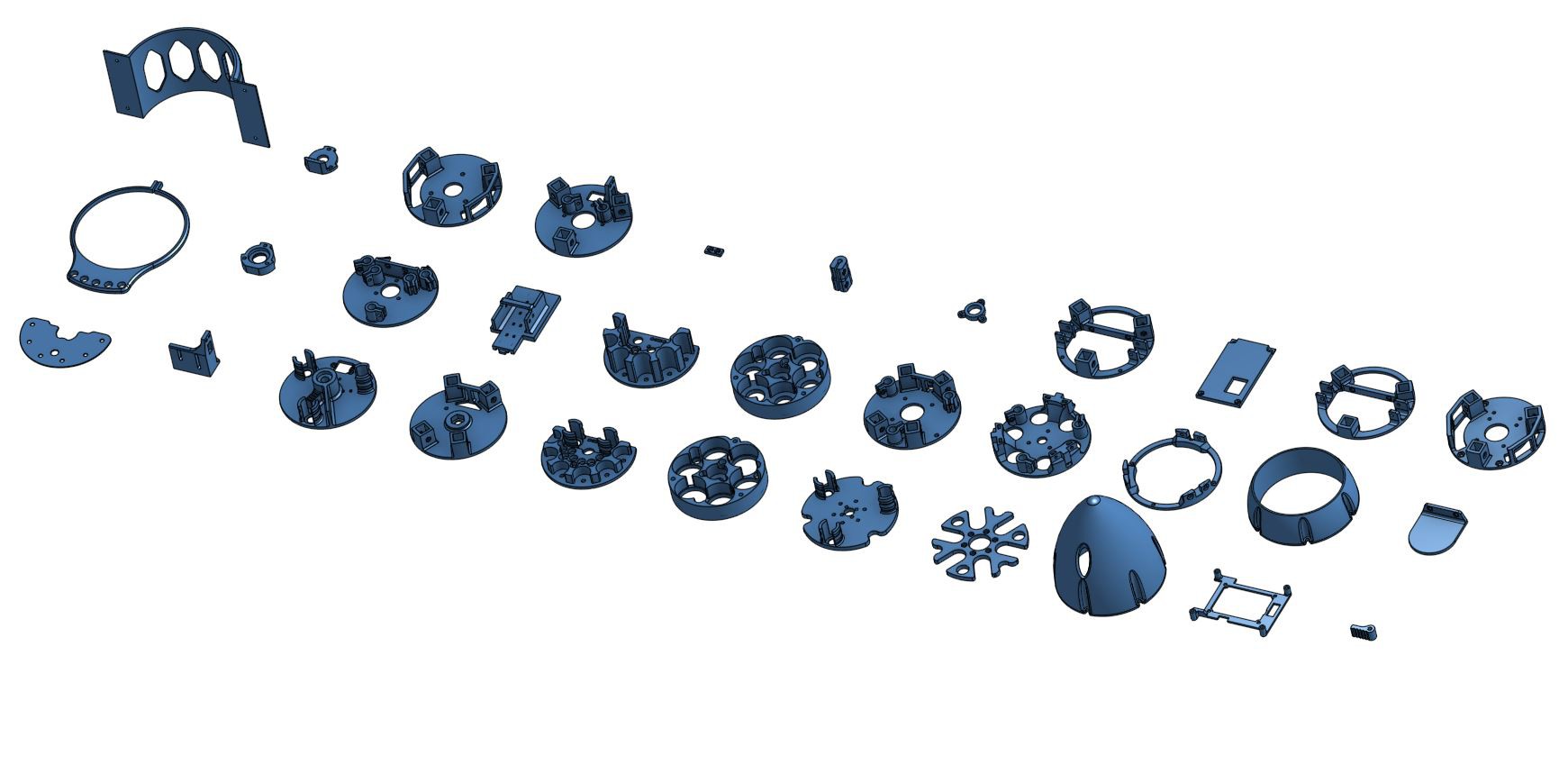
  • Assembled CAD model (and onshape features)

    alexw10/10/2017 at 10:45 0 comments

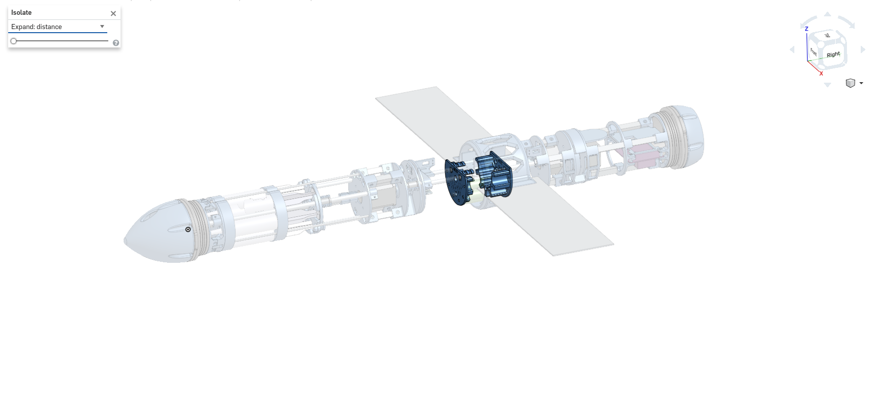
    I've finished assembling the Onshape CAD model for the third generation of the glider. It can be viewed here. There are a couple of features of Onshape that make visulisation of the model/sub-systems easier. You can hide objects which completely removes them from view (Useful for the tubing as it then allows you to select internal components). You can also isolate a component (or multiple) which makes all other components faded and makes it very clear as to what the individual components look like etc.

  • Final(ish) third generation hardware

    alexw10/07/2017 at 16:13 0 comments


    I have gone over the glider CAD model and I have changed the parts so that no post processing is required (unless I've missed something).

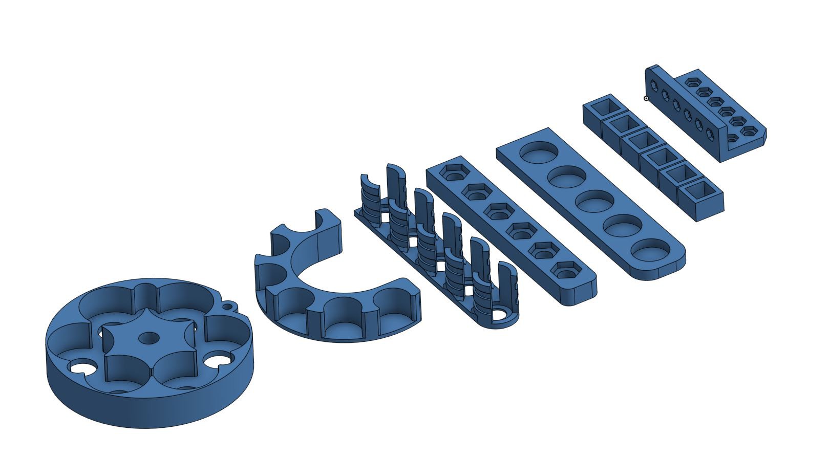
    Within the Onshape model, the test prints should be printed first and they are used to select values for the component variables.

    I am aware there is currently a lack of instructions for the third generation of hardware but all the images of the assembly can be found in the dropbox folder.

    I should update the project page soon with full instructions for the assembly of the glider.

  • Ascending and descending underwater

    alexw09/22/2017 at 21:54 0 comments

    Just a quick update regarding some testing of the new hardware: I recently had access to a pool and I was able to test the glider's new hardware in deeper water. There is currently no control software onboard, so the glider is dead reckoning using set timer delays (4 seconds down, 4 seconds up). The pitch mass is not varied during the duration of the filming. The angle of attack is currently quite steep, but this will be optimised as a PID algorithm becomes integrated. The tether at the back of the glider is only there for remote programming, which made it quicker to modify timings whilst the glider was in the water; the tether did not need to be attached whilst it was performing this gliding sequence.

View all 32 project logs

  • 1
    Build notes
    • Given vibrations throughout the glider due to the stepper motors, I would recommend using threadlock or locknuts throughout the build.
    • Most of the parts are parameterisable and should be adjusted to your printer. However, there will be parts of the prints that require a small amount of sanding/drilling to make sure that holes are the correct size.
    • If there are any errors with the build instructions or CAD components (or if you have any CAD part name suggestions - I lost imagination after a while), leave a message and it shall be fixed as quickly as possible. All suggestions are very welcome.
    • On the Hackaday page are a set of STL files with custom values for my particular printer. While these may work for your printer, it is suggested to print the files with custom part variables for your printer, determined by printing a set of test pieces as outlined further on in the instructions.
    • As the Hackaday’s project editor is slow to work with, I made all of the instructions on a google docs documents. When I ported the instructions across all the images became slightly out of proportion and there are too many images to manually change them all. You can view the images in the correct proportions if you click on the image. You can also view all of the images on the Dropbox image link
  • 2
    Preparation of PCBs

    Some board services leave tabs on the PCBs, so you can remove these and sand the edges of the board smooth.

  • 3
    Soldering SMD components

    This step uses hotplate surface mount soldering, a more detailed example of this technique, including video, can be found here at hobbytronics.

    Using a non-food hotplate, heat the PCB slightly, this allows the solder paste to be applied more thinly as it is less viscous and comes out of the syringe more easily.

    Apply the solder paste to the SMD pads, as shown highlighted in red. Use the tip of the solder paste extruder/cotton buds/kitchen towel to remove excess solder paste from the pads. Surface tension will cause the solder to go onto the pads on the atmel chip, so don't worry about connecting them all at this stage.

    Using tweezers, place the SMD components onto the board. R1/R2/R3/R4 are 10K‎Ω resistors and C1/C2 are the 22pF capacitors. Only the atmel chip is orientation specific, so make sure that the alignment dot on the chip lines up with the star on the board. Make sure that the atmel chip's pins line up with the pads on the board.

    In order to form the solder joints, heat the hotplate up to its maximum setting and watch the pads closely. When the solder paste gets near the required temperature, it will turn into a liquid, and it will then gain the silver solder appearance as it continues. Make sure that all of the solder joints have been formed before removing the board from the heat.

    Some of the pins of the atmel chip will have bridged, so use desolder braid to remove the excess solder causing bridging. Use a multimeter continuity tester to check that no pins are connected to the pin next to them.

View all 25 instructions

Enjoy this project?

Share

Discussions

Kevin Klemens wrote 05/21/2017 at 03:18 point

Alex,

This is an awesome project and i am very excited to get my materials all together and start printing (I have a Taz6). Thanks for making the files available and providing instructions, that is huge for the marine robotics hobbyists. I started a thread on the BlueRobotics forums if you wanted to join in: http://discuss.bluerobotics.com/t/open-source-3d-printed-glider-on-hackaday/1086

I've been working on really long range communications with a friend, so give me a ring when you get to that part. We have Wifi and 4G working on a Pixhawk 2.1 and we are pretty close to getting Iridium satellite comms working for our boats, but I always wanted to put the circuits on a UUV.

  Are you sure? yes | no

alexw wrote 05/22/2017 at 17:57 point

Thank you for your interest in the glider. I am currently looking at using the 4” tubing from Blue Robotics as the current design may not be watertight, due to a mixture of the endcap design and the limits of my printer. The Blue Robotics’ tubing would increase reliability of the seals and easier to produce a working prototype. I hope to have the parts purchased within a few days and will publish an update outlining the parts. Given the comments of others, I am also going to look at using a bladder based buoyancy engine, giving me a greater engine volume and reducing complexity. I will overhaul the design once my school exams have finished (a couple of months).

Once I have the glider functioning underwater, I am interested in adding an autopilot for running predetermined routes and a sensor array for data collection. I am also interested in long range communication for longer missions, using either 4G or the Iridium communication module (I was initially put off by the price though) and any help in that department would be greatly appreciated.

  Are you sure? yes | no

Kevin Klemens wrote 05/22/2017 at 19:57 point

I concur with your move to the BR 4" WTC. I've been looking at that for the hull of my vectored thrust UUV (Design idea right now). Any commonality with parts for your glider and BR products would be a good thing to make for an easier entry for people. I've physically been there to help with the WTC depth tests, so I can vouch for their numbers.

I read the below comments on oil bladders, and while a good idea, I think you're going to have more fine tuned buoyancy control with the piston style ballast tanks, but that is just my two cents. It would be interesting to see dive results using both methods.

I'll send you a PM on the command and control aspect and we can collaborate on that.

  Are you sure? yes | no

Modzer0 wrote 05/25/2017 at 15:00 point

On the oil based bladders below. The reason oil is attractive is for deeper water. When you're diving an air based system you're doubling the compression every 10m which causes changes in volume and with changes in volume come changes in buoyancy. With an external bladder which is commonly used for deep diving such as ARGO oil is the only way to go.

An alternative is to use front part of the hull itself as big buoyancy engine cylinder.

  Are you sure? yes | no

Kevin Klemens wrote 05/25/2017 at 17:46 point

I agree, if this were to be going really deep >100m I'd say oil and hydraulics would be the way to go. That's what the commercial deeper diving gliders use. The 200m Slocum looks to be using piston tanks though.

However, the real limit here is going to be the WTC. The 4" acrylic ones should be good down to 100m, but there isn't a customizeable 4" aluminum one yet, unless Alex finds one. So 100m will probably be the depth rating, which would be a good number for an inexpensive glider like this. Material cost goes up exponentially the deeper you need to go.

The reason I'm a bit against oil based buoyancy is because I've seen a few DIY oil compensation experiments (lights and servos) and none of them worked well.  It only managed to make a mess of electronics when they leaked. All the oil pumps I've seen for gliders look to be piston based with a three way valve.

The ROUGHIE glider uses piston tanks and trimmable pitch and roll and seems to have a very nice flight path.

  Are you sure? yes | no

topbloke23 wrote 03/22/2019 at 13:35 point

you only double in pressure for the first 10 meters. every ten meters after that the pressure increase actually becomes less and less.

  Are you sure? yes | no

Mike Yurick wrote 05/13/2017 at 17:37 point

Nice project, wish I had some water handy to do something like that.

Any plans for a nosecone camera?

  Are you sure? yes | no

alexw wrote 05/14/2017 at 13:51 point

I am considering using the 4” tubing/seals from Blue Robotics, as this would make it far easier to make watertight (I am going to release a project log concerning this). They have a dome endcap specifically for camera use and I was planning on purchasing one to have it available for experimentation later down the line.

  Are you sure? yes | no

Modzer0 wrote 05/12/2017 at 20:13 point

An operational tip that will help you save power is to not rely on the weight mass for pitch control. When the glider is neutrally buoyant with the pistons at 50%, or 60% if you want a bit of positive reserve in case of leaks. The larger the variable ballast the larger the reserve. There will be leaks when you least desire them. Once you trim at level , and at the neutral buoyancy position of the piston rely on the piston to control the pitch. With it being forward mounted taking in ballast will naturally put it at negative pitch and the opposite is true as well.  Brute force isn't needed with the motors, slow everything down, and go for maximum power efficiency over speed.

  Are you sure? yes | no

alexw wrote 05/14/2017 at 13:53 point

(I'm replying to both of your comments to make replying easier)

Many thanks for your informed comments. I am looking to make this a low cost platform that people are able to use as they wish, including to record the temperature/dissolved gas levels of lakes/still water. Hopefully, this will be the use case I demonstrate. It may only have quite limited utility in readily accessible water bodies particular any that are fast flowing or with tidal currents. Thank you for the comment about thermal layers in lakes, that would have been tricky to identify/figure out otherwise.

Having seen yours and others’ comments, I had another look for bladders and I found that water pouches could be viable. Using a pair and an oil ballast, this would give me a greater variable ballast (150g for 3 syringes vs 600g bladder in the same space) and hence a larger reserve. Due to your mention, I am looking at a small peristaltic pump that I could use to control the bladder and to adjust both buoyancy and pitch. However, I am likely to use the movable mass to control pitch when starting out, as I feel like this will be easier than using the buoyancy engine to control both buoyancy and pitch and will be sufficient for proof of concept.

In addition to having a reserve in the buoyancy engine in the case of a leak, I am also contemplating having some masses on the exterior of the glider, attached to the tubing by strong magnets (on the interior). In the case of a leak, an electromagnet ring would pulse on and repel the masses and making the glider positively buoyant. I have yet to work out the feasibility of this type of leak emergency system.

  Are you sure? yes | no

Modzer0 wrote 05/15/2017 at 22:26 point

If you try to maintain pitch with your movable mass system trying to hold it at  specific angle you're going to be fighting your buoyancy engine. Trim it level at neutral buoyancy. When you take in ballast you're going to naturally make the front heavier which will give you negative pitch. The more negative the buoyancy the greater the pitch. The same with positive buoyancy, the more, the greater the up angle. You get it for free with forward mounted variable ballast so use it to your advantage.

For a submerged object you have the center of gravity (G) which in your case is altered by the weight mass. Then you have the center of buoyancy (B). At rest B will come to rest directly over G.  When you decrease buoyancy forward B will shift aft. When you increase it B will shift forward which will alter pitch as a result. There's a lot of math but you can skip it because your center of gravity is variable and can be adjusted with input from gyros. If you had a fixed ballast mass then the math would be more important.  The buoyancy engine is at the front so changes will result in larger shifts in B.

The droppable weights are possible, but add a bit of complexity and unless they're secured mechanically they can fall off at the worst moments.

  Are you sure? yes | no

alexw wrote 05/30/2017 at 21:28 point

(I am replying to this comment as hackaday does not allow you to reply to a third level comment, so I cannot reply to the intended comment.)

As I understand it, the variable ballast at the front of the glider would control pitch as desired if the oil is less dense than the surrounding water. Therefore the pitch can also be correctly controlled by the buoyancy engine if it is mounted at the back of the glider, by using oil that is more dense than the surrounding water. Other than less dense oil typically being less viscous (and more available), would there be any major advantages with mounting the variable ballast at the front of the glider, than at the back?

You were also talking about using the oil bladder to achieve greater depths than with the syringes, but the peristaltic tubings that I have come across are typically only rated to 4 bar or so (30m), which isn’t close to the 100m figure that was floating around elsewhere in the comments. Is there a way to use the lower pressure tubing to achieve those greater depths or would I need to find tubing with a higher pressure rating or use a different mechanism altogether?

  Are you sure? yes | no

Modzer0 wrote 05/30/2017 at 21:33 point

You still mount the variable ballast forward. That's where it needs to be to take advantage of the change in buoyancy for pitch. When you start going deeper you're going to need your buoyancy engine and hoses to take the pressure so aluminum and heavy duty hoses will be needed.

  Are you sure? yes | no

topbloke23 wrote 03/22/2019 at 13:18 point

hi modz sorry for the late reply and sorry for replying to the wrong comment but below you said the ballast needs to be forward. then can you explain how the "seaglider" manages to have is variable ballast in the rear. and excuse my ignorance but im having difficulty understanding how you would controll bounancy by pumping oil from inside the hull to a flexible bag on the outside of the hull. as far as i can tell this doesnt change your displacement unless the oil is lighter than water. and if this is the case the variance would be so very little and seemingly not enough to change the attitude of a 600 pound machine. as you can see in this video the tubing and fittings used in the seaglider seem to be standard push-fit water hoses and the oil bladder is in the rear. 

https://youtu.be/89NN4044pIE

  Are you sure? yes | no

Modzer0 wrote 05/03/2017 at 16:24 point

As someone who has built AUVs for the US Navy I have to say this is pretty cool. The downfall of underwater gliders is they need a fairly large and deep body of water. In the open ocean they have plenty of room. It's a bit more difficult in small bodies of water because there's not really much of a power budget for any kind of depth sounder. Something that would be very useful for environmental studies is a low cost version of the Argo buoy that can be used in lakes to profile temperature, O2, and CO2.

One thing you might run into with neutral buoyancy manipulation when diving in something like lakes is a sharp thermal layer. To save power you want to manipulate the ballast as little as possible and very slowly drift down this creates a situation where you'll have it 'float' on top of the denser thermocline. You can of course just take in more ballast and power through but if you do so too quickly you may experience what we have called 'Operation Seadart' where your vehicle does an imitation of a lawn dart and doesn't have the buoyancy reserve to free itself from the bottom. It's a fine balance to dive slowly enough to get a good sensor trace, but quickly enough to gain the desired amount of propulsion, which isn't a lot.  If you want to simplify ballast control use a bladder and a peristaltic pump. It'll reduce the number of moving parts making construction simpler and give you more ballast reserve.

There are a number of ballast control methods but one you may want to consider is oil bladders, one internal and one external in a free flood area. It has the advantage of not being as compressible as air so your buoyancy doesn't change with depth using an external bladder.

  Are you sure? yes | no

ActualDragon wrote 04/30/2017 at 01:44 point

in the movement video, the green weights are to move it forward or whatever. it looks the same size as a AA battery. if the final goal is to go untethered, couldn't you replace those with batteries?

  Are you sure? yes | no

alexw wrote 04/30/2017 at 08:17 point

The green weights in the video are actually 18650 cells, which are lithium ion batteries that is a little larger than an AA batteries, hold more energy and are rechargeable. In the video they are not powering anything and they're just there to show where they will go.

  Are you sure? yes | no

ActualDragon wrote 04/30/2017 at 12:57 point

oh ok. nice project btw!

  Are you sure? yes | no

Legrange wrote 04/10/2017 at 10:16 point

This is cool, I have an affinity for things that go under water.

Curious as to how precise your syringe control is and how precise do you need it to be to function properly? Have you done any real life experiments on the control system, if not, how soon before you try things out? How long before you have a workable prototype of the whole thing?

  Are you sure? yes | no

alexw wrote 04/12/2017 at 10:26 point

I have finished printing about half of the components, and the other half should be quicker to print (I printed the larger components first). I will then be able to assemble the glider and see if anything stands out as being incorrect. Following that, I will design the control circuits and control software.

The capacity of the syringes (180ml) compared to the volume of the glider (~6000ml) is 0.03, whereas the Slocum glider's volume change (450cc) compared to volume (52000cc) is 0.009. From these figures, it seems that the change in density will be sufficient. That being said, I am still sceptical of my glider, as the Slocum glider is clearly much larger and I am unsure as to what degree that will affect the required volume change.

The threaded bolt used to drive the syringes allows for a very precise control over the volume of water taken in; hooking up a stepper motor to the syringes makes it look like repeatable volume change of 0.1cc is possible.

I am currently in the lead up to exams, so will be able to put minimal time into the project over the next 2/3 months. However, following that, I have about 3 months free in which I will do a large amount of development and I hope to come to the point where I am able to perform real life tests on the control systems (simple ascending/descending and pitch control).

  Are you sure? yes | no

Legrange wrote 04/12/2017 at 19:35 point

Thanks for your reply. It's good you're keeping grounded and sceptical. I look forward to hearing more about this project as you get the time to work on it.

  Are you sure? yes | no

Peter McCloud wrote 04/04/2017 at 04:06 point

Great looking CAD model

  Are you sure? yes | no

alexw wrote 04/04/2017 at 09:25 point

Thank you. Functionally, the model has a way to go, but it's more or less there visually

  Are you sure? yes | no

Similar Projects

Does this project spark your interest?

Become a member to follow this project and never miss any updates