-
[M] Starting the PCB
10/03/2022 at 13:12 • 0 comments[14:15]
![]()
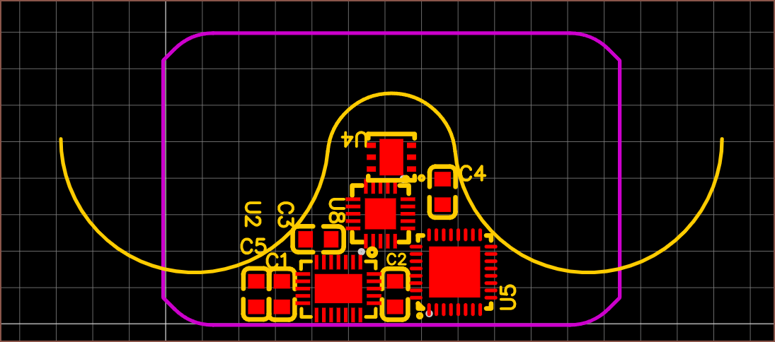
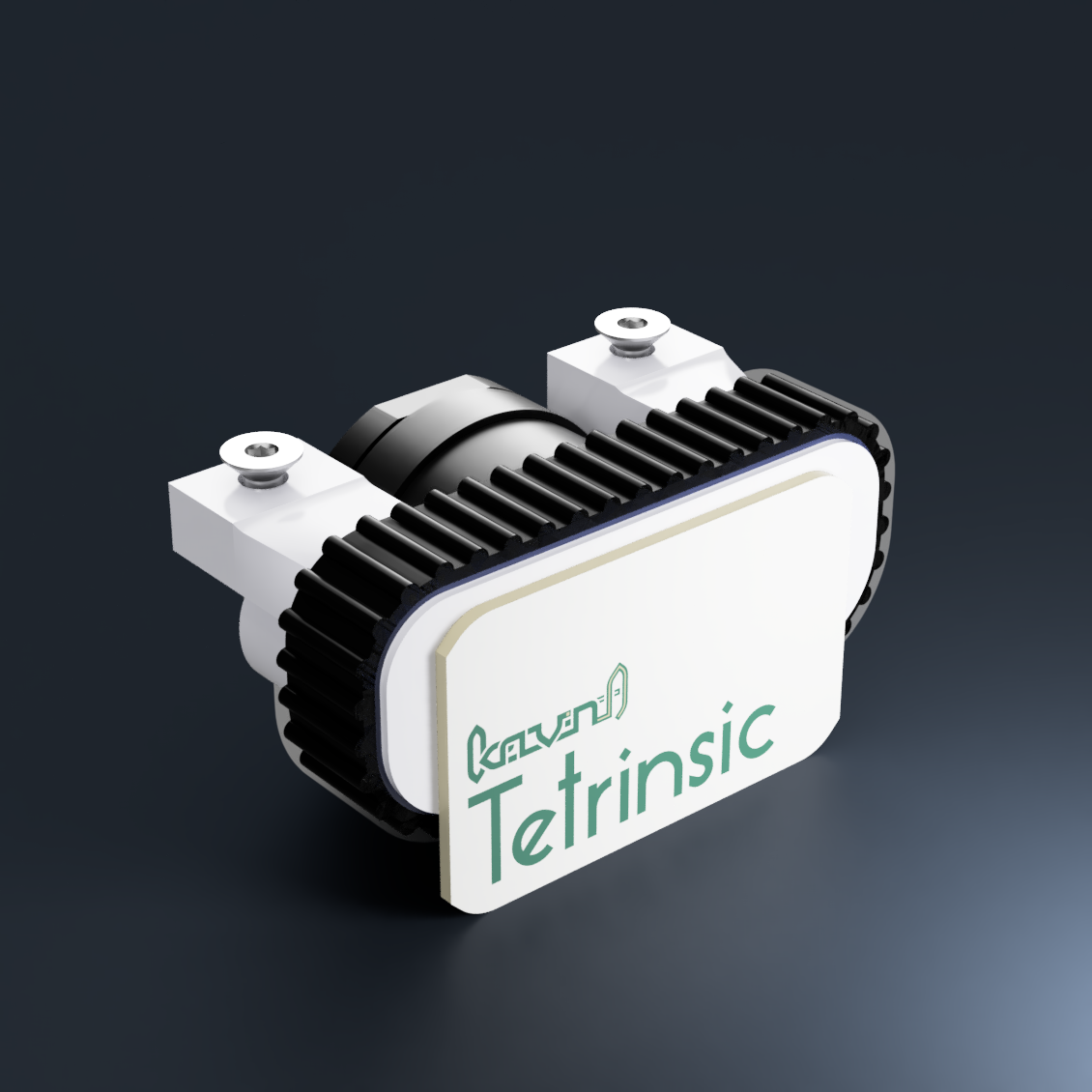
This is a 25x16mm PCB with 0603 capacitors. I haven't yet made the switch to 0402s yet I've already had to increase the size of the board to 25x16mm and reduce some passives to the micromanagement 0402 package, as well as shuffle the IC's around, just so that I could have any resemblance of fitting things into the space provided. At least the motor mount nuts are fully covered by the PCB now, so Tetrinsic should look a bit more aesthetically pleasing for those that enjoy seeing things like Apple's PCBA designs.
![]()
Whilst increasing the amount of shared passives and seeing how many more the MCU wants, I found out that the M032 chip is the one with the USB controller. The M032TD2AE has the same amount of flash as the M031 I discovered last log and reduces the IO to 23 pins (from 27). It's 20p more expensive and Digikey has almost 2X the stock. Since this M032 could be more useful in any future electronics projects in the future (due to that internal USB controller), I'm going to use it.
It would be really nice if I can flash the MCU through USB, but if not, I'm likely going to make the 27 ohm resistors (specified in the datasheet) external (since I don't have a lot of board space to go around).
[16:15]
![]()
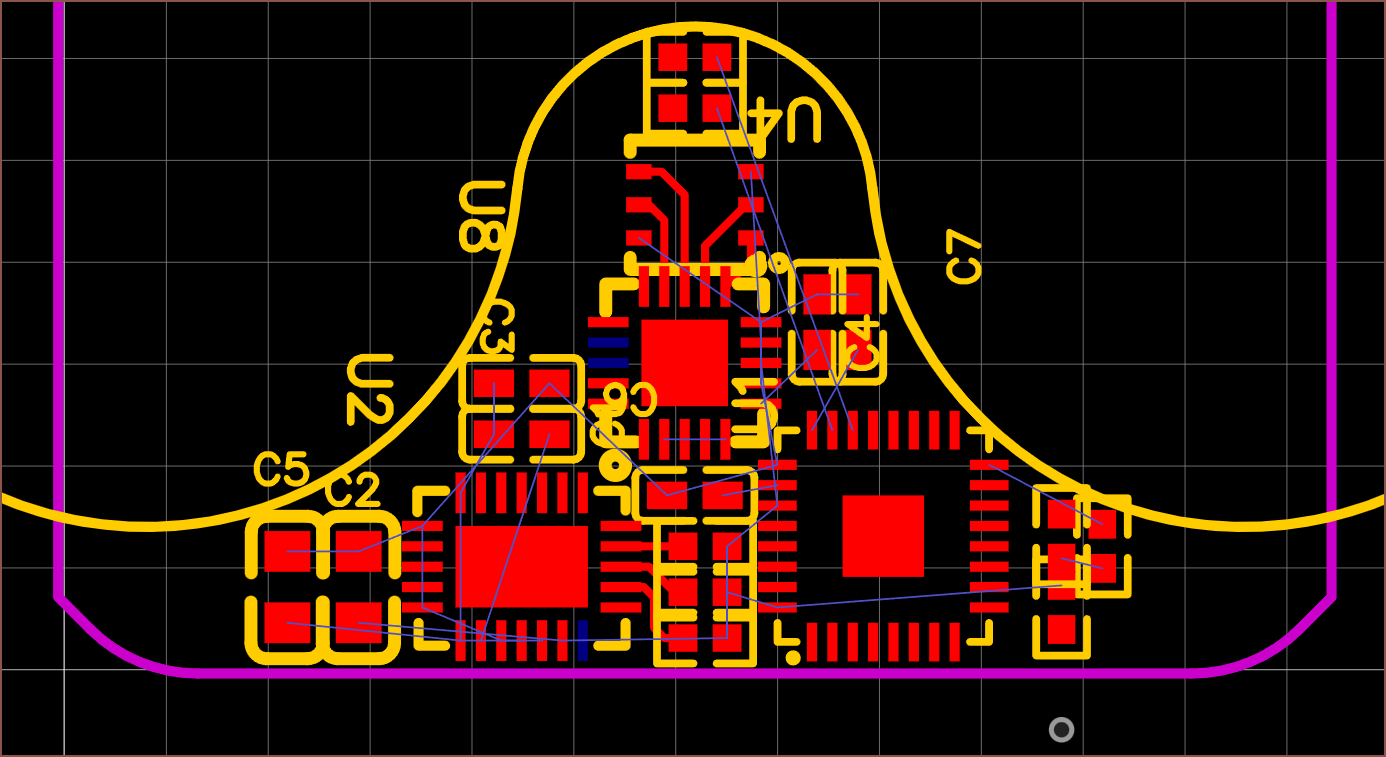
Exciting. I've managed to cram in all the passives I know I need at the moment. Don't mind the silkscreen at the moment. I've also started connecting some pads together to see how close or far ICs need to be so that things are routable.
The blue pads are the not-connected ones that I can delete if needed. I'm assuming that the magnetic sensor doesn't need the pad so I've already deleted it to make routing easier. I've also shrunk the M032 pad so that I can fit vias.
[23:15]
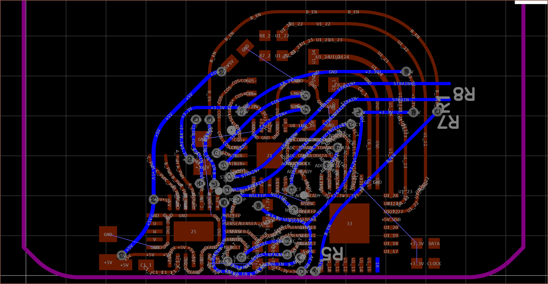
![]() This is the routing I've been able to get today. The next time I find time, I need to connect the other 4 PWM pins to the MCU and figure out what pin I can use for the I2C feature in the "Universal Serial Control Interface". Then I need to start making some external cable pads.
This is the routing I've been able to get today. The next time I find time, I need to connect the other 4 PWM pins to the MCU and figure out what pin I can use for the I2C feature in the "Universal Serial Control Interface". Then I need to start making some external cable pads. I'm also going to need to increase the height of the PCB to 16.5mm.
-
[T] Tetrinsic as master control
10/02/2022 at 02:34 • 0 commentsI'm currently wondering if I could have one of the Tetrinsics as a "master" IC, instead of requiring a seperate microcontroller for use in #Tetent [gd0090]. The current IC of choice clocks in at a speedy 48Mhz, but the 16K of RAM is a bit of a concern.
New Chip
I went to Digikey to see what other options are out there, and this chip is convinient:
![]()
The M031TD2AE seems to be a 64KB version of the initial chip I found in the previous log. I then looked into the memory sizes of popular DIY keyboard microcontroller choices, and quite a few of them are 32KB, so 64KB should be large enough to upload a full input device firmware.
Another cool thing is that it seems that JLCPCB's SMT service has it in stock too.
For a 4x4 package, it sure comes with a lot of juicy features. The money saved from omitting the multiplexer has gone straight into a more ideal microcontroller chip, as my ex-VAT chip total is currently £133.
I've also missed the deadline for the XIAO keyboard contest, so using their microcontrollers is no longer a soft requirement.
I2C Device Addressing
Yesterday, I determined that I was going to use I2C as the communication protocol between Tetrinsics. The only concern was how I was going to set the device addresses.
Right now, I'm hoping that I can have a "sense" line on the ribbon cable and detect the resistance between the I2C data line or something like that. If each Tetrinsic adds a set ohmic value to the resistance, firmware should be able to determine how far down the daisy chain it is. For example, if 5k resistors are used, 15k resistance detected between the data and sense lines would mean that the firmware gives the current Tetrinsic the 3rd valid device address.
Further Delays
Along with now having to learn about the large world of microcontrollers (at least enough to create a working schematic for it) I'm thinking of creating PCBs for Tetent and #Tetent Timespy [gd0136] to save on shipping costs. I'm also thinking of having 1 large Digikey order instead of 2 or 3 seperate ones.
-
[T] Using a microcontroller
09/30/2022 at 12:12 • 0 comments[14:00]
So I'm watching VoidstarLabs' new keyboard build and hear about IO expanders and microcontrollers, and so I go onto digikey to take a look, since I've still got concerns about controlling the MP6543 through an expander. What do I find immediately? RP2040 chips that go up to 133MHz for 88p for a MOQ of 1!!
The issue is that I don't have much board space at all, so the 7x7 package is too large. The current IO expander is a 4x4 package, so I set the relevant filters and found this:
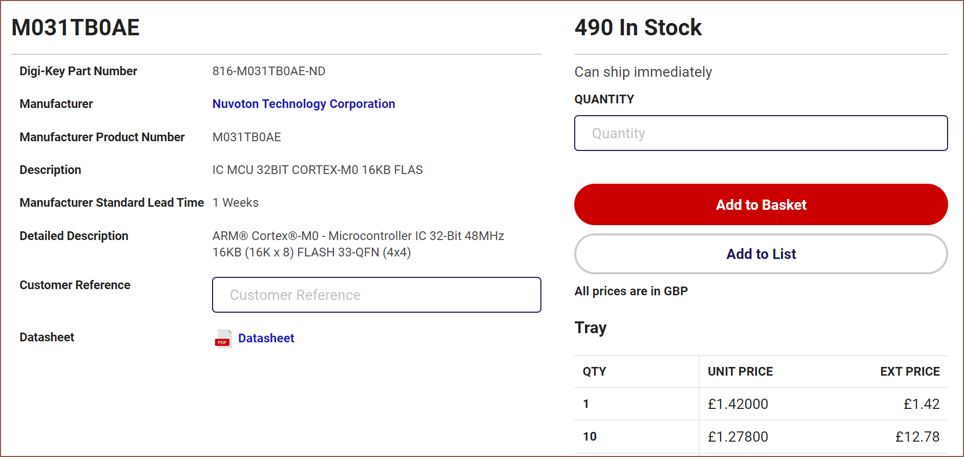
![]() 32 bit. 48Mhz. 16K flash. 2K RAM. Near half the cost of the IO expander:
32 bit. 48Mhz. 16K flash. 2K RAM. Near half the cost of the IO expander:![]()
Squints
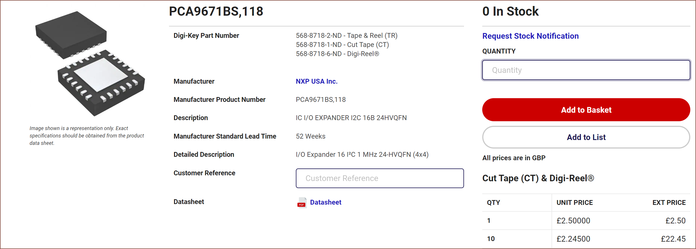
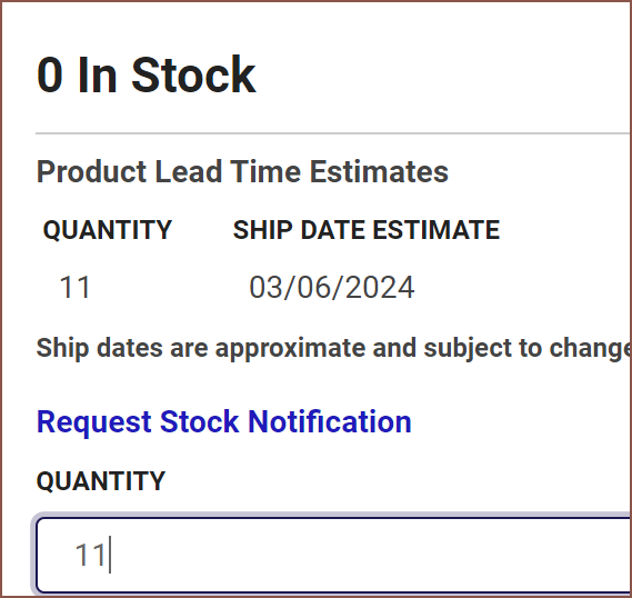
![]() No... no... that can't be right. I wouldn't have picked this if the stock quantity was this low... it... it should've been in the thousands or something!...
No... no... that can't be right. I wouldn't have picked this if the stock quantity was this low... it... it should've been in the thousands or something!...Finds a snipaste on the 27th Sep when I first found the chip:
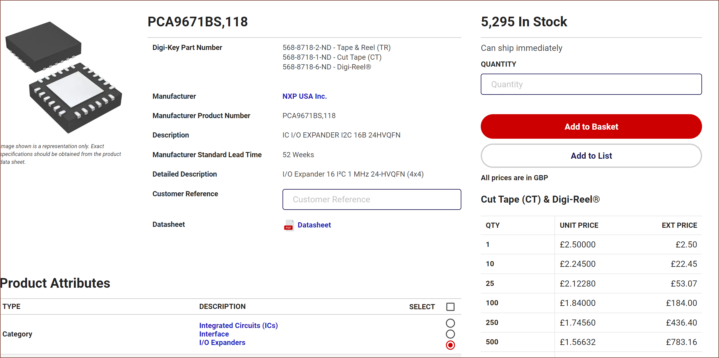
![]() Wha? There were 5K in stock 3 days ago? Wha... what happened??? So I would've had to recalculate either way????
Wha? There were 5K in stock 3 days ago? Wha... what happened??? So I would've had to recalculate either way????Well... I guess I'll start reading the 280-odd page datasheet then... and hope that 490 is enough to stay in stock without beign enought to get bought out by the local factory or something.
Anyway, I was thinking that the microcontroller could do all the motor control and encoder processing and just ping back to the master every microsecond (1kHz) or so. Every time I think I'm close to having something, I find a new low in limbo (reference to the Limbo Dimension in the Minecraft Dimensional Doors mod).
[16:30]
I'm looking at the £2.54 EFM32PG22 and it could be an option for a microcontroller with built in 16 bit ADC, but the documentation is too sparce to get an idea of if it's a usable alternative to the £3.79 discrete ADC. The £2.95 MSP430I2020 also exists with 2x24b ADCs, but I can't seem to find the 3 or 4x24b options, nor have I determined if 16 IO pins are enough. It might be, but I'm once again still having troube understanding what its ADC can and can't do.
Those are the 2 options that cost less than ADC + M031 (£5.16). The M031 has a 12bit ADC, meaning I can remove the 2:1 switch chip.
Also, I'm currently reading that strain guages have 10mV of full-scale deflection, so using 16x gain is likely unrealistic for getting usable signals.
-
[M] Direct ADC connection
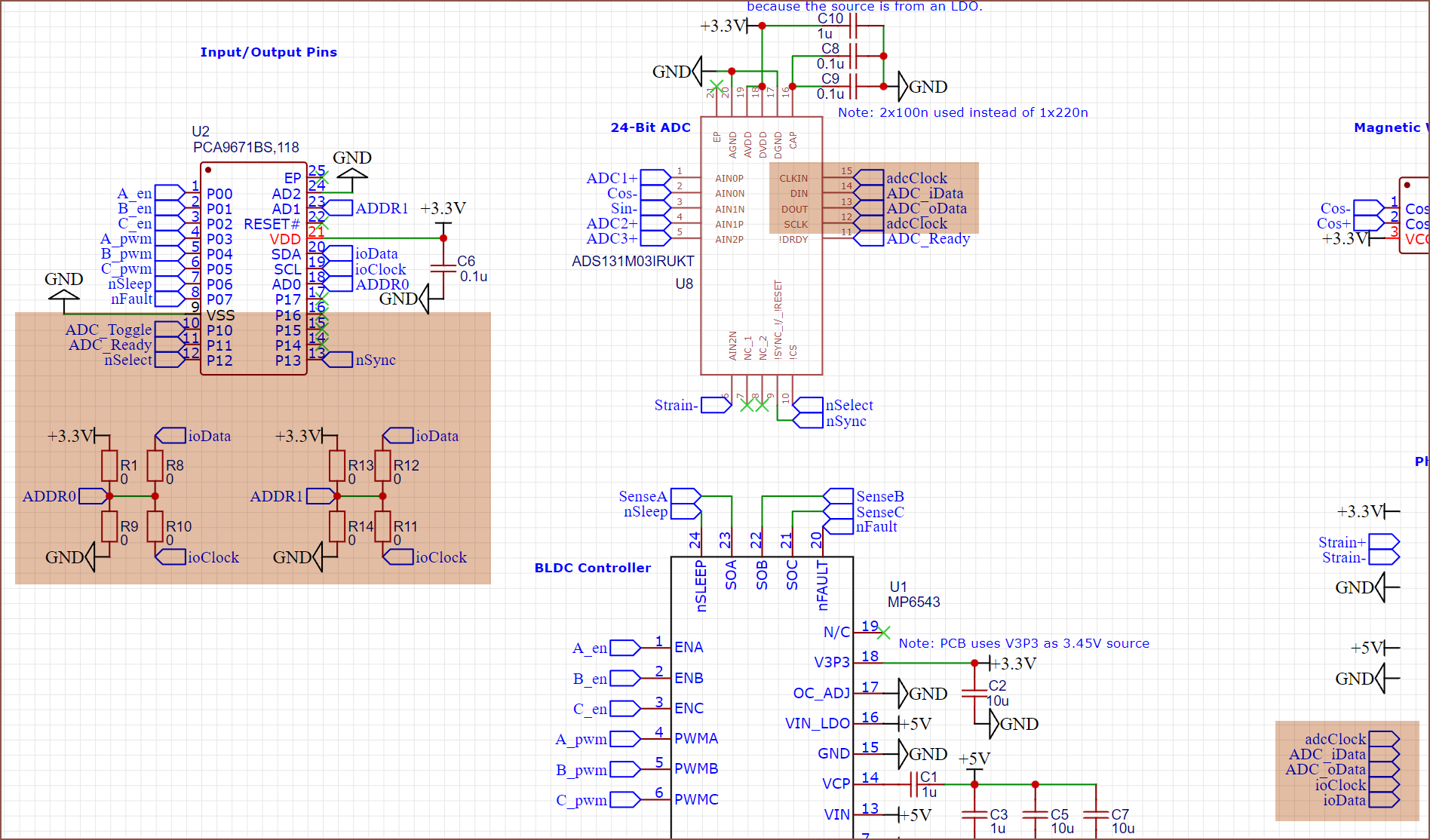
09/28/2022 at 12:30 • 0 commentsI was still worried that there were going to be ADC SPI issues with the idea I had last log, and realised that SPI shares all but the CS line. This means that I can cut out the Channel0/1 thing, increase the amount of address configurations to 16 and increase the ribbon cable to 5 lines.
![]()
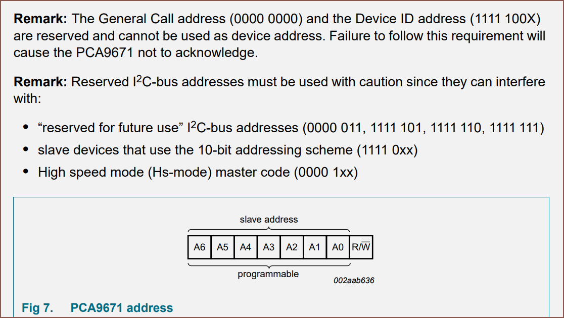
It should mean that the ADC's can use a faster, 8.192MHz channel and hopefully the ioData line isn't as congested. I just haven't checked if any of the 16 device address combinations are device addresses that are recommended against:
![]()
-
[M] I/O Expander
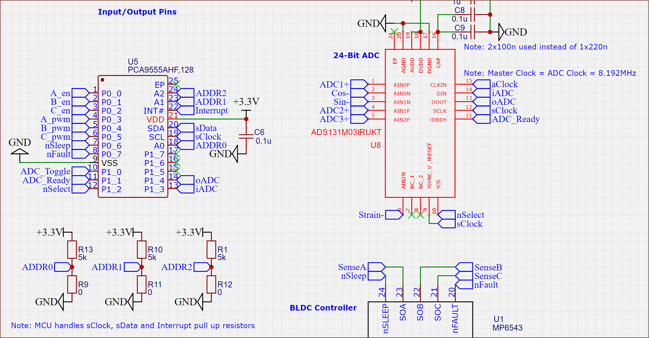
09/26/2022 at 18:02 • 1 comment![]() I read through the Ti version of the PCA9555A schematic and it's actually simple to implement, hardware wise. I'm not even sure if I'd need to use the interrupt pin, but even with it, my ribbon cable is only 4 lanes now:
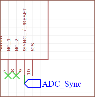
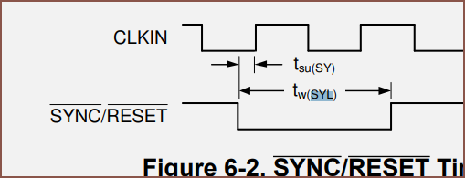
I read through the Ti version of the PCA9555A schematic and it's actually simple to implement, hardware wise. I'm not even sure if I'd need to use the interrupt pin, but even with it, my ribbon cable is only 4 lanes now:![]() I might give nSync an IO pin instead of using the serial clock. According to my calculations with a 8.192MHz ADC clock, as long as the serial clock is over 4kHz, the chip will just synchronise and not reset. I can't imagine a situation where holding the pin for over 1/4000 of a second would have any adverse effects, and should facilitate a reset of the chip in a timely manner.
I might give nSync an IO pin instead of using the serial clock. According to my calculations with a 8.192MHz ADC clock, as long as the serial clock is over 4kHz, the chip will just synchronise and not reset. I can't imagine a situation where holding the pin for over 1/4000 of a second would have any adverse effects, and should facilitate a reset of the chip in a timely manner.The reason why I feel that the interrupt may be useful is because of the ADC's "data ready" pin and the motor controller's nFault. Not like it costs money or much space to keep it or omit it, so I'll keep it.
The next steps are to double check that I've set up the sense pins correcty, see if I can implement suggestions on circuitry for taking ADC measurements and then start creating the custom footprints for the PCB.
-
[T] PCB schematic... fails.
09/25/2022 at 13:17 • 0 comments[12:30]
I just woke up and realised that the next data in or data out signal for the ADC won't be ready by the next master clock cycle.
I want to make a solution that can take at least 8 daisy chained Tetrinsics. That means I've got 64 bits each way to shift in and out. That's a multiple of 2, so maybe I could install some kind of chip that toggles every 32 clock cycles. Alternatively, I can see if I can swap out a pin for another clock signal. A 3rd idea could be to use oLatch (latch for output pins) as a serial clock.
I'm also thinking that 1k samples in an actuation window may be more than required considering that high-performance gaming mice poll at 1000Hz (80 samples in an actuation window). I don't know how fast I need position data, but I'll assume 1kHz would have me covered there too. At the end of the day, being too fast would be a nice problem to have.
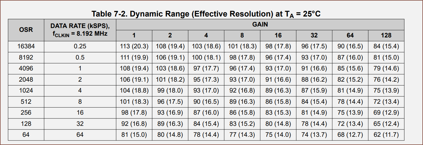
![]() The 8 channel ADC is still a bit pricey, and even more so if I opt for the 24-bit option, so I'll stick with the 24-bit triple ADC already in the design. Going from 32ksps to 2ksps would increase my effective resolution from 14.8 to 16.6 bits at x16 gain, with lower gains approaching 17 bits.
The 8 channel ADC is still a bit pricey, and even more so if I opt for the 24-bit option, so I'll stick with the 24-bit triple ADC already in the design. Going from 32ksps to 2ksps would increase my effective resolution from 14.8 to 16.6 bits at x16 gain, with lower gains approaching 17 bits.I also need to look to see what pins need pull-up resistors.
[16:30] The story becomes even more complex now. Apparently, it's somewhat complex to share the 74hc595 and 165 clock pins. I'm going to look into I/O expanders that use I2C. Even with 32.768MHz clock on my initial shift register strategy, the effective signal clock from Tetrinsic's point of view is 512kHz. Thus, I wouldn't need a >1MHz I/O expander for an alternative. Most of the cheap ones are 400kHz by quickly skimming Digikey.
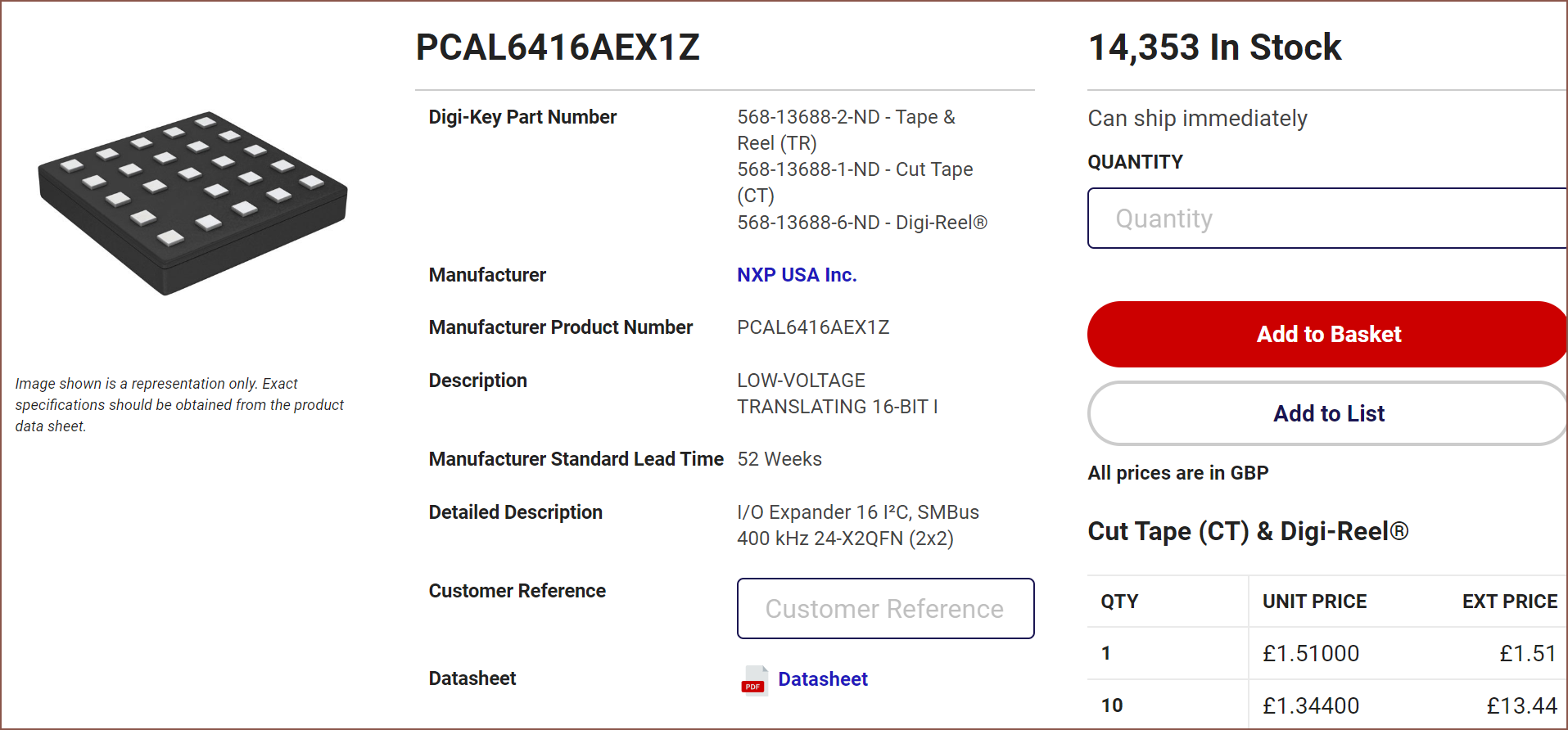
![]() This seems nice. If this is the kind of product I'm looking for, it'll be +55p on the BOM and it's smaller than 1 singular 74HCxxx, though this only assumes that I can route all the connections with 2 PCB layers. There's also a 3x3 BGA package, and I'd probably use that.
This seems nice. If this is the kind of product I'm looking for, it'll be +55p on the BOM and it's smaller than 1 singular 74HCxxx, though this only assumes that I can route all the connections with 2 PCB layers. There's also a 3x3 BGA package, and I'd probably use that.[17:30] It seems that ony 2 of these can be used on a line.
![]() The cheapest one that allows 8 addresses is £1.94 and a 4x4 package. It's a bit of a squeeze but it fits.
The cheapest one that allows 8 addresses is £1.94 and a 4x4 package. It's a bit of a squeeze but it fits. -
[M] PCB Schematic
09/24/2022 at 19:47 • 0 comments[22:50]
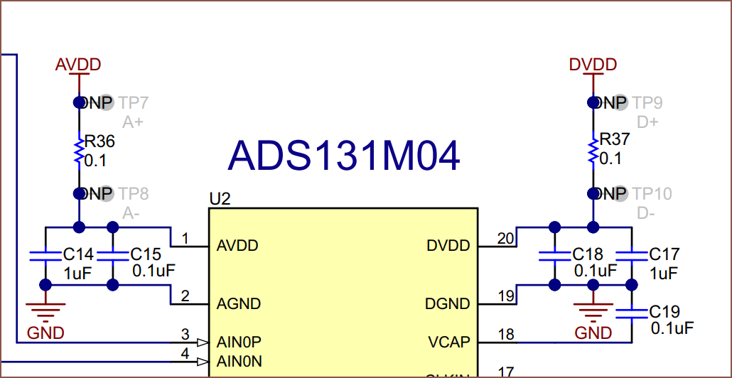
![]() Ok. I've spent the past 2 days drawing up this schematic. The license is going to be under some permissive option but I've just been reading datasheets and connecting the dots so...
Ok. I've spent the past 2 days drawing up this schematic. The license is going to be under some permissive option but I've just been reading datasheets and connecting the dots so...It's a good thing that I haven't just press "Buy Now" on anything yet because, as you can see, there are 6 chips and not 5 like in the previous model.
One thing I have learned is the "bypass capacitor" which is 0.1uF (and 1uF and 10uF) as a kind of industry standard. Another notable mention is that I'm going to see if I can get away with the analog and digital input voltages coming from the same source. It sounds like to get any usable-for-high-resolution analog source is going to require experimentation and osiliscopes, so I should just get any PCB out of the door now.
My chronological schematic creating process in detail is written below.
Magnet Angle Chip
![]() Ok that's 1 chip down.
Ok that's 1 chip down. Motor Chip
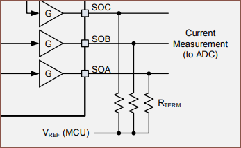
![]() Is that everything? Wait a second... aren't those sense pins analog?
Is that everything? Wait a second... aren't those sense pins analog?![]() Nouh!! I'll come back to this later.
Nouh!! I'll come back to this later.![]()
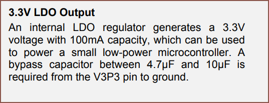
??? Didn’t you say 0.47 a moment ago?
![]() Hmm. Ok I'll assume the paragraph is the correct one. But nice! There's a 3.3V regulator in this chip, so I don't have to send that power from the MCU.
Hmm. Ok I'll assume the paragraph is the correct one. But nice! There's a 3.3V regulator in this chip, so I don't have to send that power from the MCU.Switch Chip or new ADC?
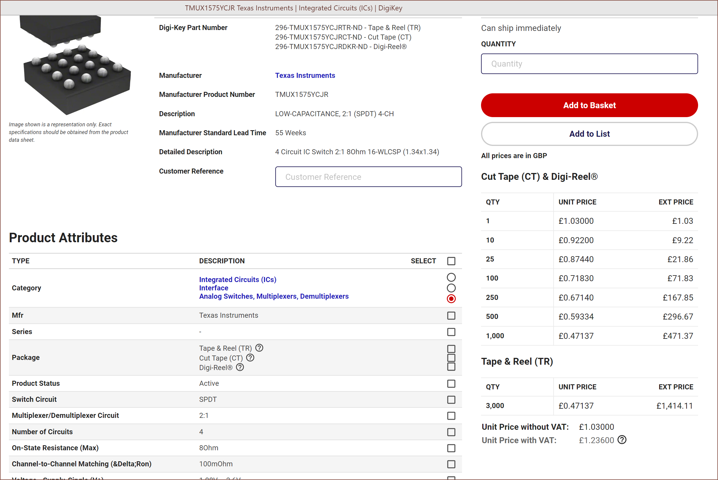
![]()
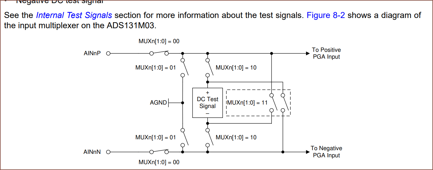
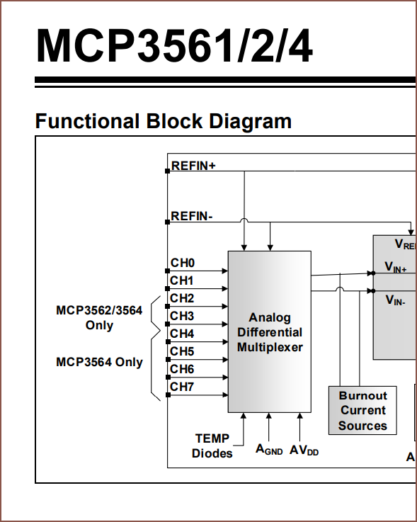
This sounds like the thing I'd need, but this is seemingly the only option that fits and is under £5 each. What I can do is use this in conjunction with the internal multiplexer of the ADC to switch between Signal+,Signal- and Sense,AGND:
![]()
The issue is that I don't have a free pin on the 595 to controll the switch pin as of now. There's also the option of looking for a new chip. I've found the MCP3561:
![]()
Here's my idea:
- Strain on channel 0 and 1
- Swap the aat101 for one of the single-pin versions (like 003)
- Sin on channel 2
- Cos on channel 3
- Sense on channel 4 - 6
![]() But that's the worst case option.
But that's the worst case option.A second 595
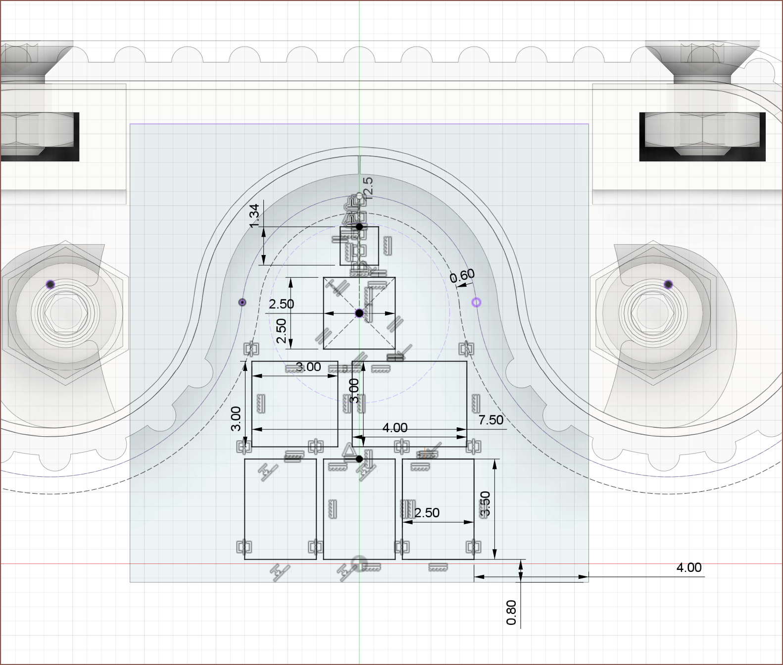
![]() By increasing the PCB to 16x16mm, I could get this layout and also have plenty of output pins with the dual 595 chips. That ultrasmall 1.34 is also the only chip that would even fit in that space.
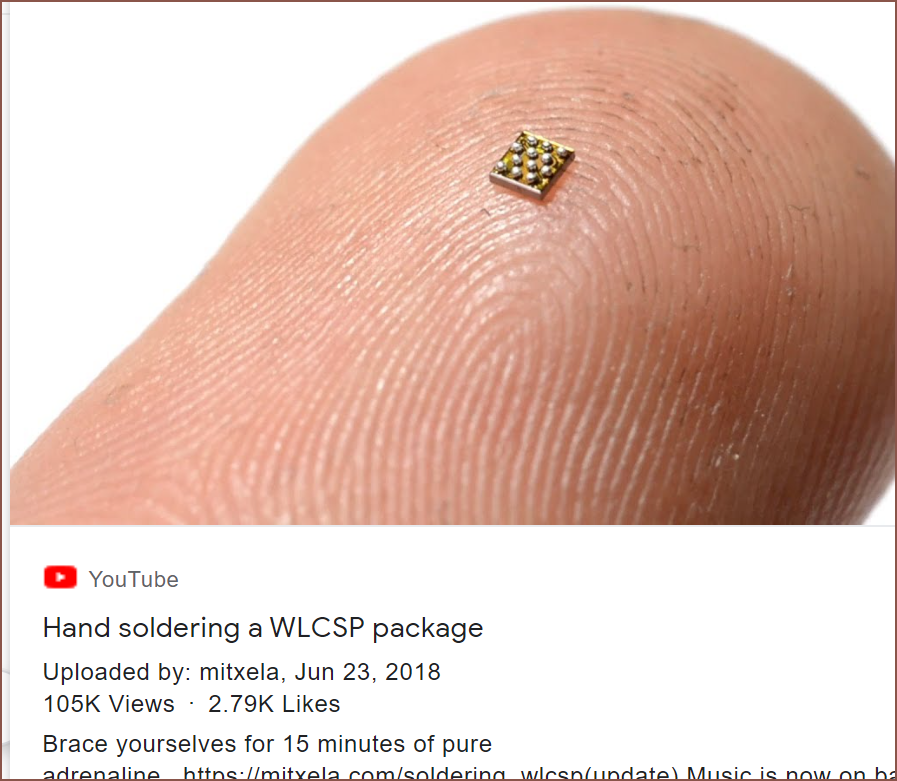
By increasing the PCB to 16x16mm, I could get this layout and also have plenty of output pins with the dual 595 chips. That ultrasmall 1.34 is also the only chip that would even fit in that space. ![]() HAHAHAH. I'd probably have to buy spares with that kind of size.
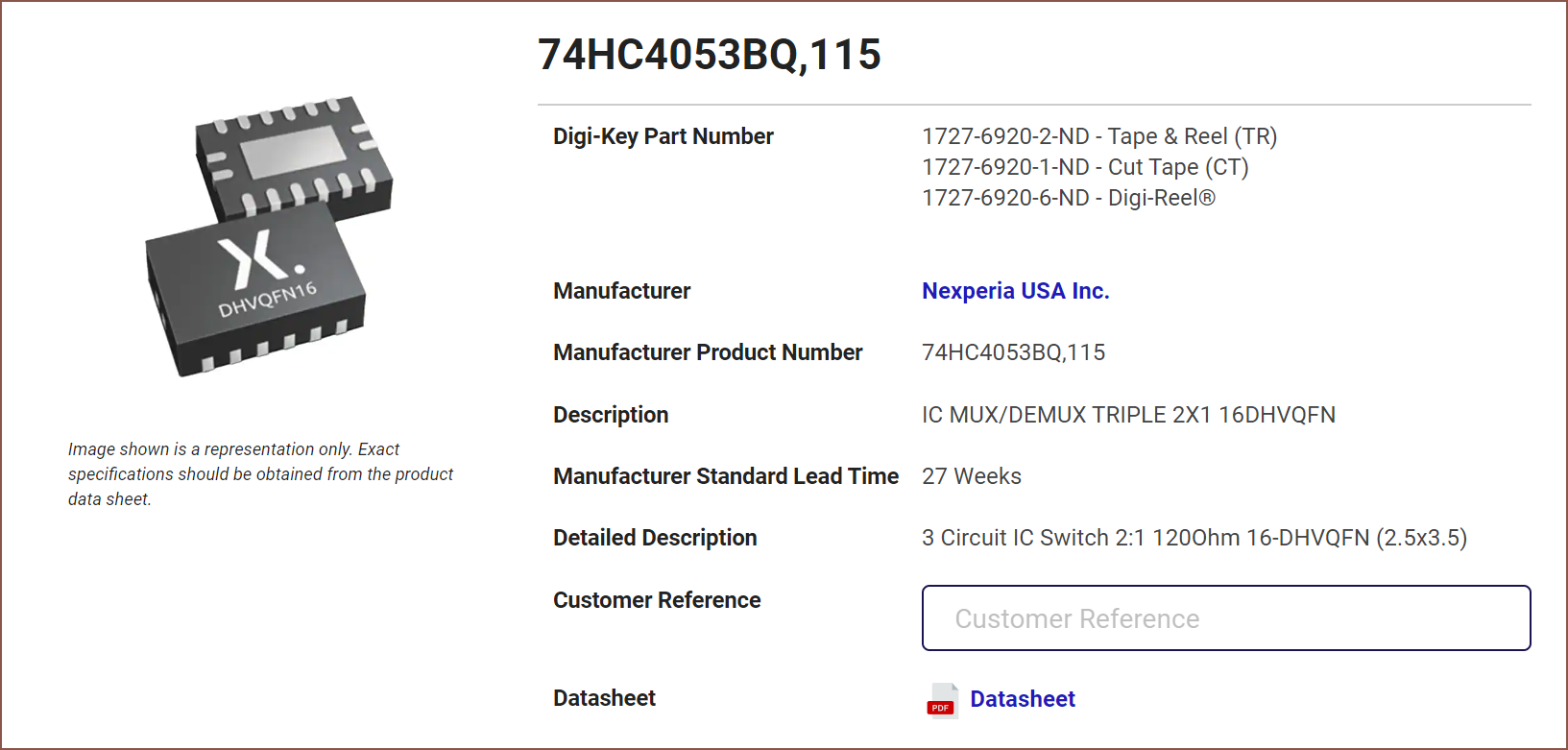
HAHAHAH. I'd probably have to buy spares with that kind of size.![]() I found this, and it's half the cost as well as being the same sized package as the other chips like the 595. I'm kind of worried about the 120 ohm resistance, but I think the ADC has a much higher impedance anyway.
I found this, and it's half the cost as well as being the same sized package as the other chips like the 595. I'm kind of worried about the 120 ohm resistance, but I think the ADC has a much higher impedance anyway.![]() This is probably a much less riskier run, and I just had to increase the board width to 20mm.
This is probably a much less riskier run, and I just had to increase the board width to 20mm.ADC Effective Resolution
Reading datasheet of ADC...
![]()
What's even the point of 24-bit if I'm not even hitting 16 when the noise is added in?
Adds/Removes components needed for the 8 channel, 16-bit ADC.
Price is £132.49 for the current ADC and £139.78 for the proposed new ADC.
But wait. I've got 7 channels I need to scan through and there's only 1 ADC doing the work. That's
153600/7 = 21942 samples per second.
(Before starting on the schematic, I got some button press numbers. The fastest I could actuate a keyboard press was 0.08 seconds. The last thing I want to happen is that my speed-increasing input device isn't fast enough to keep up. Lets say I want 1000 samples for keypresses for high precision and low latency. That works out to a minimum of 12.5ksps. At this moment, I don't know if I need more or can get away with less samples, so I set that as the target)
Returning to the ADC, this means I can only use the 32 OverSampling Rate option as 64 would mean I get less samples than the target. Thus, I'd only get 12.6-12.8 bits of data (with the remaining 3ish being noise I assume?).
![]()
Meanwhile, on the current ADC, I can do 32K samples at 128 OSR and get these numbers (1,2,4,8,16 gain)
![]()
There's no 16 bit variant of this current ADC though, which might've saved some money.
The Clock Signal
I just realised that:
- I've got a free pin now that I don’t need to send 3.3v.
- I can't send the clock pin for the bit shifters via the bit shifters.
I might be able to go back to one 595.
More ADC work
![]()
What am I even supposed to do with this? Isn't this to connect to OTHER chips and not the MCU?
![]() uhhhh... CAN'T I USE THE CLOCK??? I think I'm gonna risk it and go down to 1 595--
uhhhh... CAN'T I USE THE CLOCK??? I think I'm gonna risk it and go down to 1 595--![]() No I can't; the time period is too long.
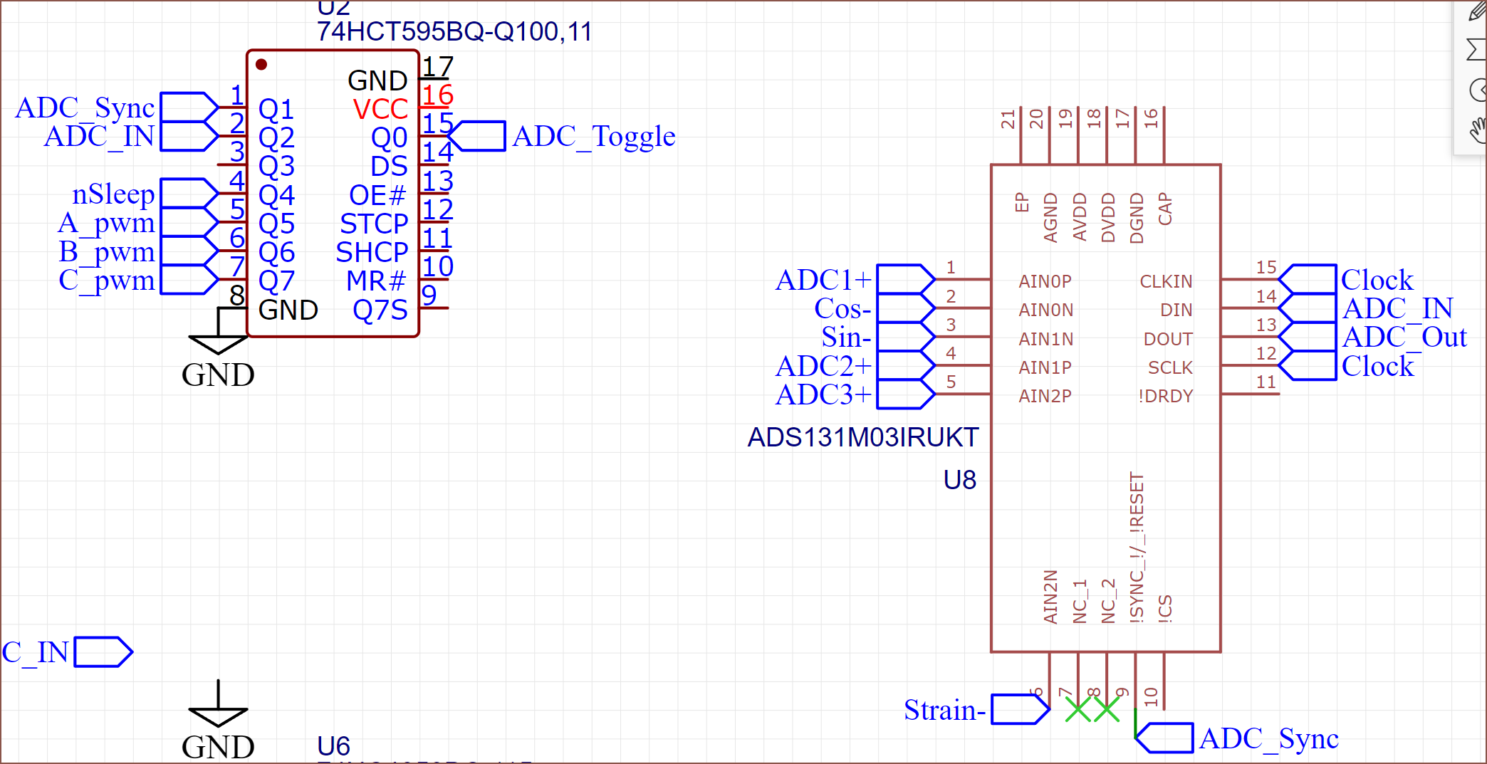
No I can't; the time period is too long.![]() Do I even need a chip select pin? Reads relevant part of datasheet. No I don't, because the 595/165 means that it's as if each chip now has it's own MOSI and MISO line instead of sharing.
Do I even need a chip select pin? Reads relevant part of datasheet. No I don't, because the 595/165 means that it's as if each chip now has it's own MOSI and MISO line instead of sharing.The 74HC595 and 165
I read some Arduino docs and other sources and found out that if I connect both register clock pins to the same clock, what will happen is that the output pin signals would just cascade down the chain. I don't want that. This means that I need to add a "Latch" line to the ribbon cables.
Additionally, it seems that the 165 can't share this latch pin since it'll result in undesirable behaviour. Thus, a 5P cable would be needed.
I also found out that "I/O Expanders" exist which can do input and output, but to get one that works at the 8.192MHz used for the 24-bit ADC, it's going to add another £2.68/each (minus about 90p by removing the 595/165) to the BOM for a 16 pin chip. That'll be nice though since I've only used less than half the available input pins on the 165, but I could use more output pins.
Just go with 20mm wide.
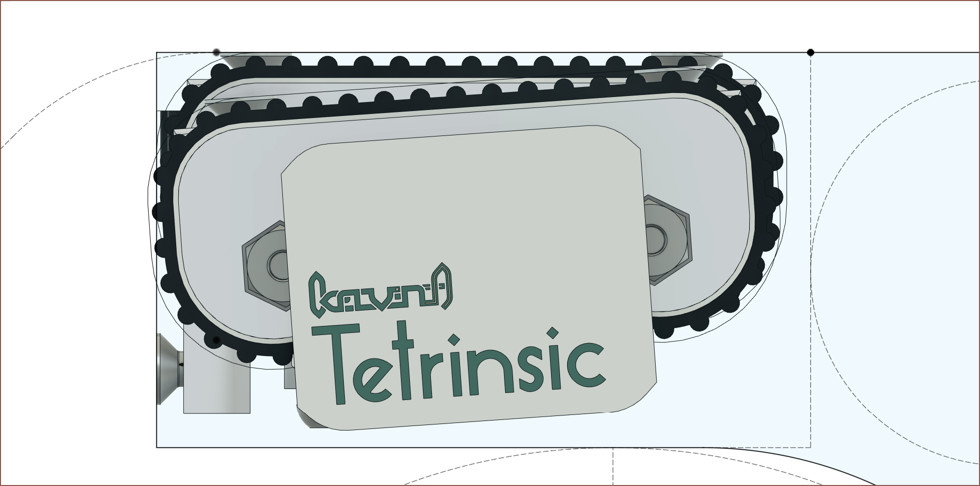
![]() I really should just make the board wider to accomodate for wider ribbon cables. It doesn't even make that much of a size difference for this currently-untested 4 degree slope (for Finger4 on #Tetent Timespy [gd0136]).
I really should just make the board wider to accomodate for wider ribbon cables. It doesn't even make that much of a size difference for this currently-untested 4 degree slope (for Finger4 on #Tetent Timespy [gd0136]).And to end off Day 1, finishing the 165 part of the schematic:
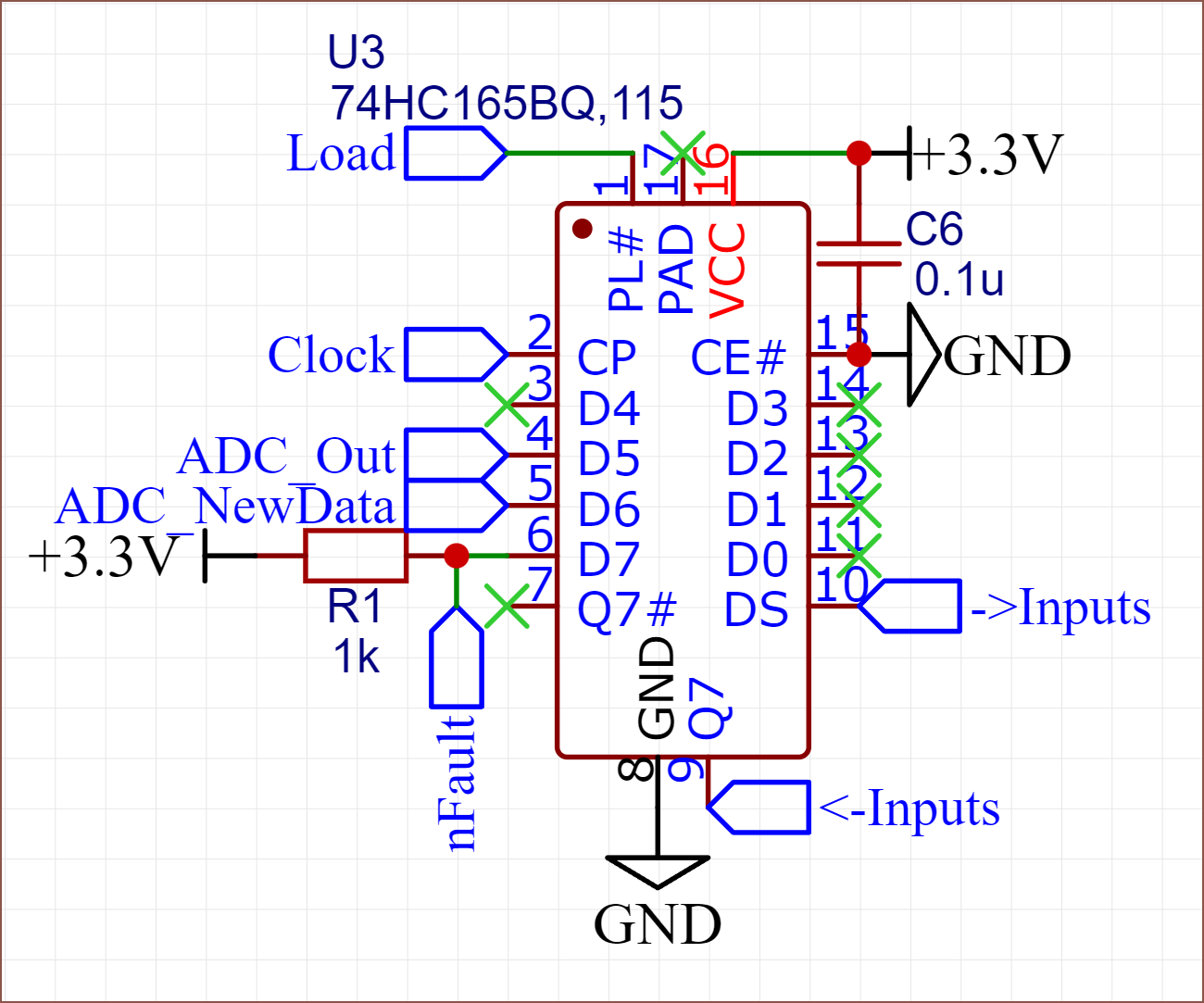
![]() I don't know what to call this second latch pin so I've named it "Load".
I don't know what to call this second latch pin so I've named it "Load".Day 2 started with me wondering if there was a board that used the MP6543
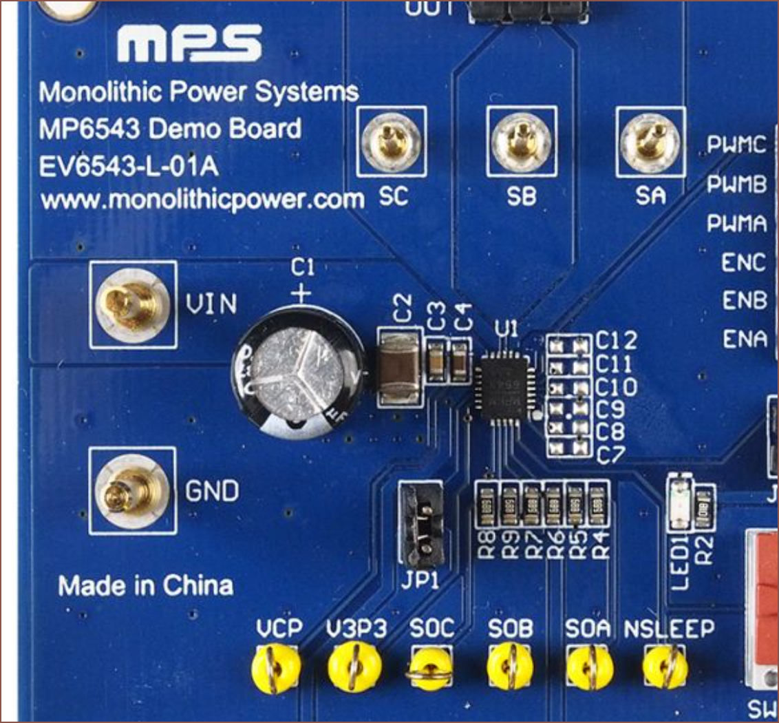
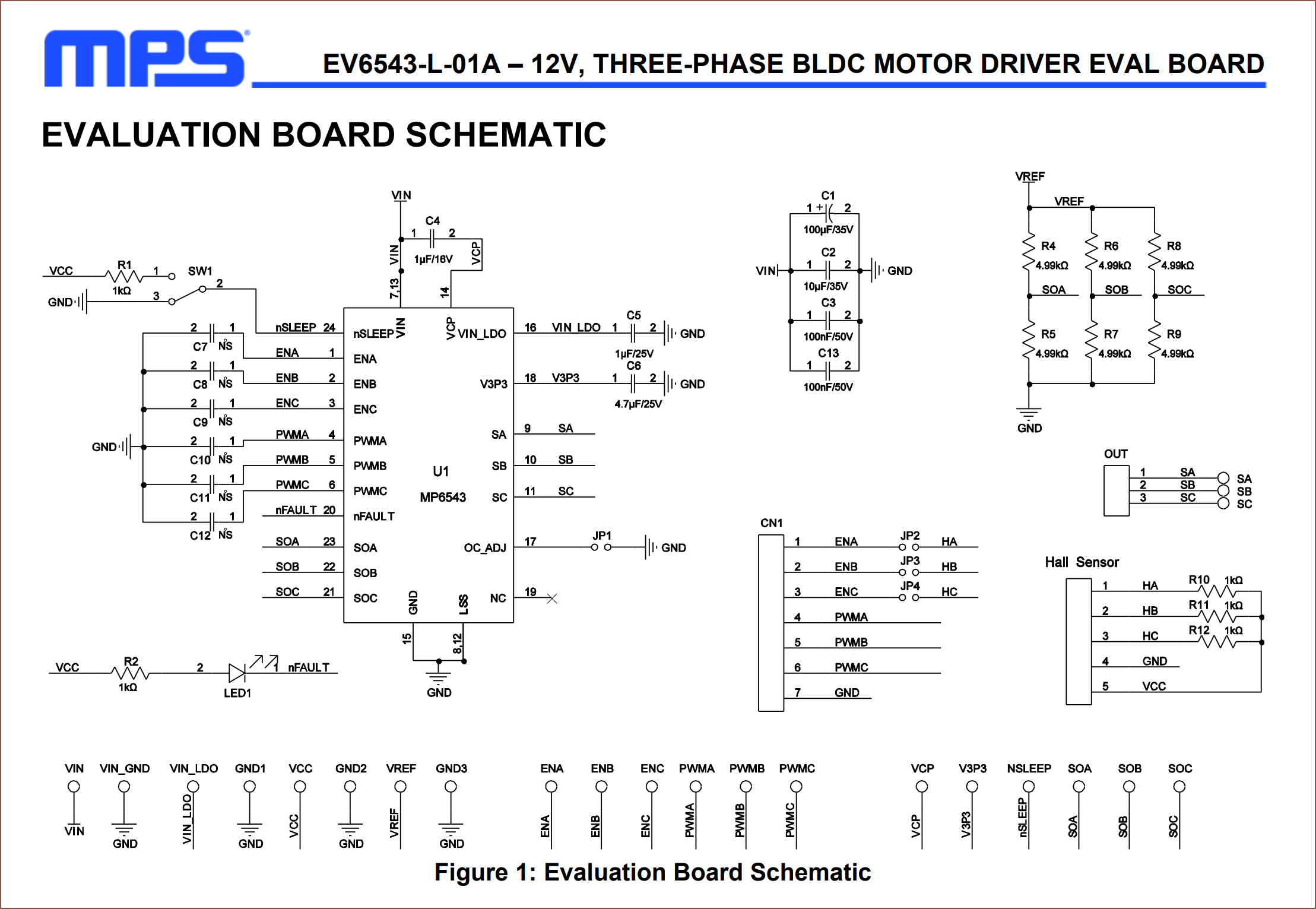
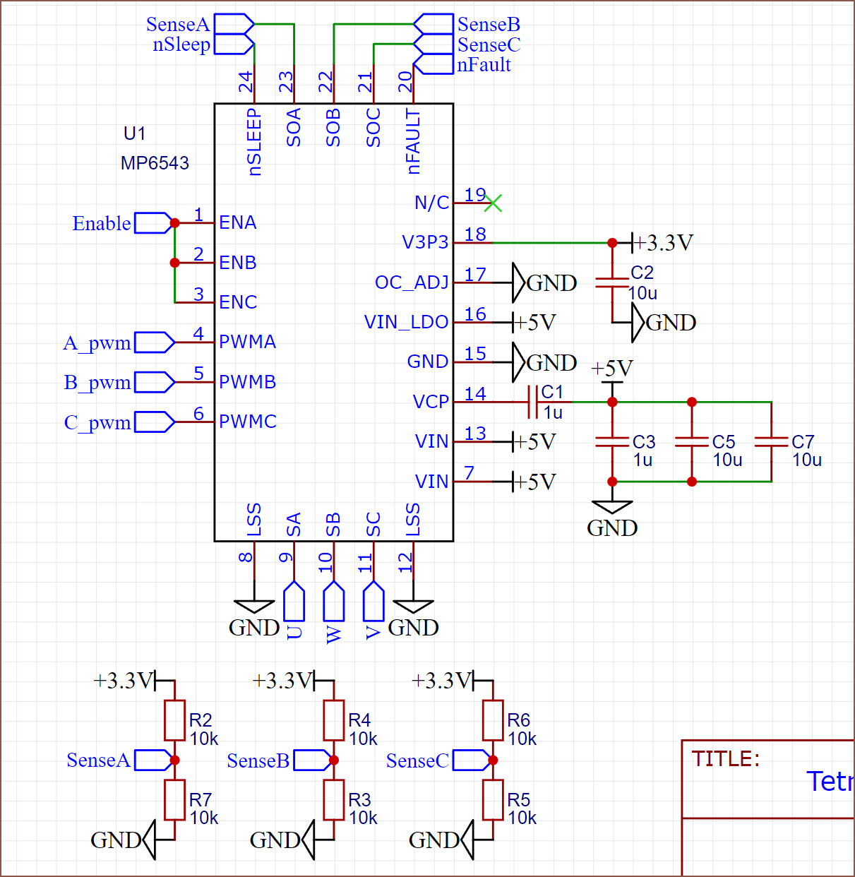
![]() Oh, there is. What MASSIVE capacitor is that though?? I was wondering why the 5V capacitor was never specified. Is it like the large one used for stepper drivers?
Oh, there is. What MASSIVE capacitor is that though?? I was wondering why the 5V capacitor was never specified. Is it like the large one used for stepper drivers? ![]() Ah, a schematic. It's a 100u, 35V capacitor? And I assume the other 3 are for something analog-smoothing related? I don't remember something large like that on the SmartKnob View. It's a shame I could only find an interactive BOM and not the schematic. Anyway, it seems that:
Ah, a schematic. It's a 100u, 35V capacitor? And I assume the other 3 are for something analog-smoothing related? I don't remember something large like that on the SmartKnob View. It's a shame I could only find an interactive BOM and not the schematic. Anyway, it seems that:- .47u was indeed a mistake for V3.3.
- I guessed correctly that V-in uses a 1u cap. I assumed it was the same as the V-in-LDO, which specified a 1u cap with at least 10V tolerance.
- V-in-LDO uses a 25V cap instead of a 16V. Interesting.
- I didn't expect that the V-ref stuff was supposed to be a voltage divider.
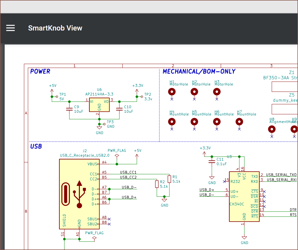
Google: smartknob view schematic
![]()
Oh. I can just search that and it comes up? ![]()
That's a not-so-tasty, tasty amount of circuitry. ![]()
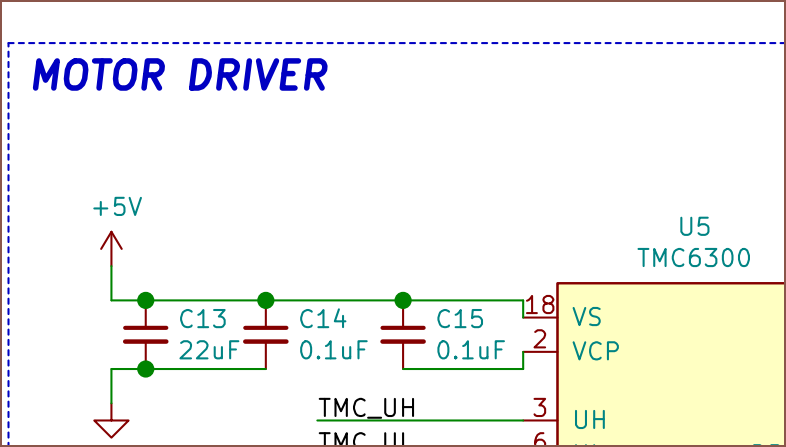
Huh it's actually similar to the mp6543 in a way. 22u is also a more reasonable bulk capacitor value to work with. ![]()
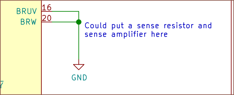
YOU DON'T SENSE ANYTHING?!!?! How though??? I thought you needed both current and rotor position for Field Orientation Control! Well I've already done all the work and the extra chip is like 40p/each so I'm not going to rip it out now. It just means that I can take more samples of the main analog things and less samples for the motor currents.
![]()
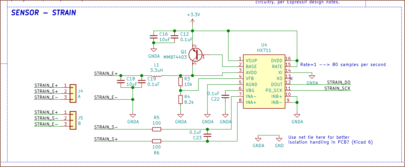
He's never putting the chip in standby either? ![]()
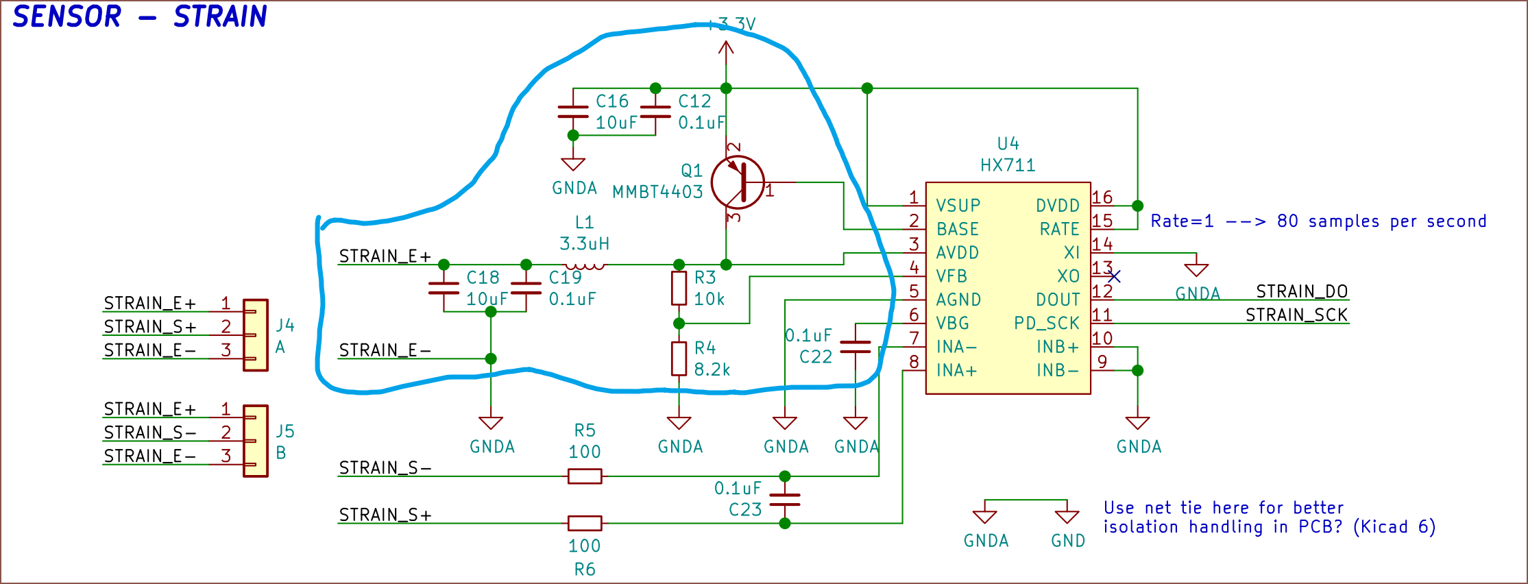
What is all this? Is this a HX711 exclusive? More MP6543 motor controller work
![]()
Ok is this better? I don't want to have to source multiple capacitor values, so I've done:
- 4.7u ->10u (max allowed in datasheet)
- 22u -> 2x10u for a total of 20u
- I'm also going to change all resistors to 5K. This includes the nFault pull-up resistor I think I need.
I wonder if there's a similar demo board for the ADC?
![]()
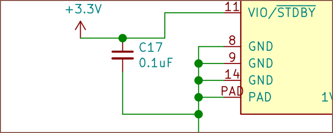
Even more capacitors?? These bypass caps are everywhere. Oh, and how am I doing AVDD?
![]()
Does this mean I could use the LDO from the MP6543? I'll try it. Right now, I'm a bit more concerned on how I'm going to fit everything with only 2 traces (and 0 ohm resistors) to work with. JLC's price goes up a lot if I ask for 4 layers.
And that's how I got the current schematic.
I've likely missed a few considerations here and there, but I think this log is a bit more useful than "I spun this schematic up over the last 24 hours.".
I do think the solution I've got is more versatile than if I only made a PCB with an angle encoder on it, since now someone could easily make a non-split, 8 Tetrinsic keyboard by soldering a daisy chained collection to 5 pins on the MCU, or it could be integrated into more traditional keyboard designs as the pin count cost is low. The alternative would've been to add all the other components on a single PCB that the MCU is soldered onto.
I'd also like to mention that it feels like I'm playing 2048 a bit.
- #TetInventory [gd0039] can't really be designed because I don't quite know what additional things I need in a backpack along with Teti (cables? table clamps? wrist rests?).
- #Teti [gd0022] progress has been stalled because Tetent can -- and has -- influence(d) design tweaks, as well as the lack of CR600S (see #Printer Repair [gd0137]).
- #Tetent [gd0090] can't exist at the moment because there's no such thing as a "motorised slide encoder", let alone one small enough to be used as a keyboard switch replacement or pressure sensitive.
- Tetrinsic hardware seems viable, but I won't know yet because there's no small PCB I can just add to my AliExpress cart.
- So now I'm here, creating a daisy-chainable, pressure sensing, BLDC encoder + controller on 20x16mm of board space.
- Hm. So then it's a miniaturised SmartKnob non-View, designed for a different use case?
-
[T][M] PCB concept (and project name)
09/21/2022 at 20:12 • 0 commentsAs you can see, the name has changed:
![]() This is because it doesn't seem that there's a merge between a linear slide potentiometer and a rotarty encoder, so this device is now just "Tetrinsic". Actually, drop the "encoder" since I my other project titles aren't "#SecSavr Suspense [gd0105] 3D Printer" or "#T^2 Tiles [gd0095] Robotic Wall". Consistency. On the other hand, maybe I should actually be doing that so it's more obvious what the project is. I feel like my project titles would get pretty long if I did that though. Are my hover descriptions not good enough?
This is because it doesn't seem that there's a merge between a linear slide potentiometer and a rotarty encoder, so this device is now just "Tetrinsic". Actually, drop the "encoder" since I my other project titles aren't "#SecSavr Suspense [gd0105] 3D Printer" or "#T^2 Tiles [gd0095] Robotic Wall". Consistency. On the other hand, maybe I should actually be doing that so it's more obvious what the project is. I feel like my project titles would get pretty long if I did that though. Are my hover descriptions not good enough?Anyway, the PCB.
![]()
It's a 15.5mm square. JLCPCB will let me have a thickness as low as 1mm whilst keeping the white and the same price, so I've done that. This makes the model 18.85mm thick, so maybe I could get 19.5mm minimum spacing. This assumes that I could use a 2 layer PCB though. For the artistic side, I've decided to have my logo as silkscreen and project name as a plated copper pad. Obviously, this will only work if I don't need traces there.
![]() It's pretty close, but there's enough surface space for the 5 chips. I also dug around the datasheets to deduce that the MP6543 needs 4 output pins and the 24-bit ADC needs 5? Looking at the datasheet, I'm hoping that I can have the master clock and the SPI clock connected together, reducing my required output pins to 4.
It's pretty close, but there's enough surface space for the 5 chips. I also dug around the datasheets to deduce that the MP6543 needs 4 output pins and the 24-bit ADC needs 5? Looking at the datasheet, I'm hoping that I can have the master clock and the SPI clock connected together, reducing my required output pins to 4. I'm thinking of soldering the 3 sets of flexible cables straight to the 4mm of space on either side, and passive components fit around the available space around the magnet sensing chip. One is the cable from the motor, and the other two are the daisy-chain link cables. One cable (likely the motor) would have to go over another one of the cables to fit. I expect that I'd need at least 4 traces in the cables if I'm able to find a place to solder power wires for the motor.
[Goes back to JLCPCB]
Oh nvm as soon as I select "lead free" finishing process, I'm either looking at a decently priced green or 4x for white. That's fine until 4 layers where 15 white PCB's is $77, so I should fully expect to silkscreen everything so that I (hopefully) only need 2. Wait... silkscreen everything? Silkscreen is white, right. How white?
![]() White enough for my science. Wait, that means that I could totally get "white PCBs with green silkscreen" by just inverting the normal silkscreen. I'll remember that.
White enough for my science. Wait, that means that I could totally get "white PCBs with green silkscreen" by just inverting the normal silkscreen. I'll remember that.![]()
I've also added that signiature greenish beige PCB edge colour. Nice, so I can do this and then I can go down to even 0.6mm boards without paying extra, and I can get the board delivered faster. I'll use 0.8mm; with this, 19.5mm spacing should certainly be doable, which apparently is the higher end of the "standard key spacing" specification. I also might not need a case cutout after all.I wonder how far off this render is from looking like the "future first proof of concept" now. That was a roundabout way of saying that I think I'm getting close to a design that will actually exist in the real world.
[22:44]
This is what 19.5mm spacing looks like in the #Tetent Timespy [gd0136]:
![]() It's going to be pretty close, but I'd be pretty satisfied if I can get this. Actually, I'm somewhat suprised that I can DIY something this unproven yet so professional looking run. I wonder if I should add 3 dots in the top right to make the board look even more advanced though.
It's going to be pretty close, but I'd be pretty satisfied if I can get this. Actually, I'm somewhat suprised that I can DIY something this unproven yet so professional looking run. I wonder if I should add 3 dots in the top right to make the board look even more advanced though.![]() It certainly looks a lot less plain.
It certainly looks a lot less plain.![]() I'll pass because the branding looks perfectly good as is on Tetent.
I'll pass because the branding looks perfectly good as is on Tetent. -
[T] Other uses of Tetrinsic
09/21/2022 at 12:25 • 1 commentPerhaps I should rename "Tetrinsic Switches" to "Tetrinsic Slider", because that's what it is. It's no longer a collection of switches, but 1 motorised slider encoder. I'm using this as an all-in-one input device for #Teti [gd0022], but it's nice to see what other thing I could use these likely-over-£15 sliders for.
It seems that the main idea for those interested in the SmartKnob View for something smarthome related, so I created a quick concept of what a Tetrinsic smart thermostat could look like:
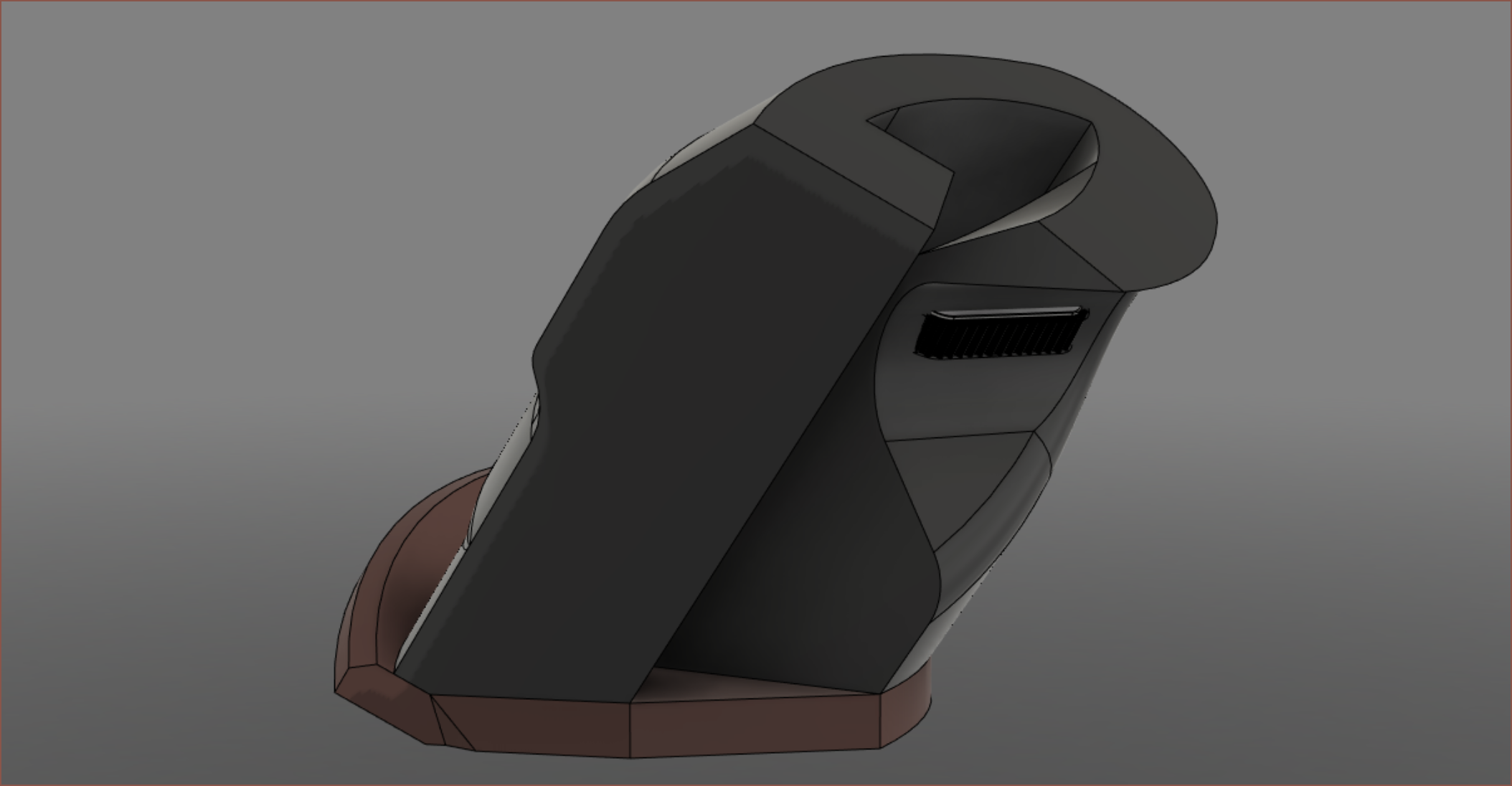
![]() The concept uses an 2.8" square display with outter dimensions of 83x60x20mm. I just put something together that looked about right. I don't use smarthome stuff so I wouldn't know if the screen needs to be larger or something. Obviously, similar rotary encoder interfaces (like microwaves and FDM 3D printers) would be something similar looking to the above.
The concept uses an 2.8" square display with outter dimensions of 83x60x20mm. I just put something together that looked about right. I don't use smarthome stuff so I wouldn't know if the screen needs to be larger or something. Obviously, similar rotary encoder interfaces (like microwaves and FDM 3D printers) would be something similar looking to the above.If you can fit it, it could be a scroll wheel in a custom mouse.
![]()
This was the design of the Thaxis mouse without the joysticks and with a Tetrinsic slider where the thumb rests. It's a vertical mouse design. It became #Tetent Turntable [gd0038] and eventually #Tetent [gd0090]. I wanted to put a motorized scroll wheel on here, but at the time, I was thinking of a nema 14 stepper motor. It could be a physical extension of a software synth.
![]()
Just imagine fewer of these, more spaced apart and shorter. Unless you've got the budget and the sliders above are >20mm apart from each other, then it's just shorter. -
[R] Sourcing chips
09/21/2022 at 11:53 • 1 comment![]() Yikes. This took 8 hours to curate. At least now I know I'm creating a switch that's likely to be >£15 per each. Considering that many ergo keyboards, the Twiddler3 and the Charachorder all cost north of £150, this isn't too terrible. Behind the monitor, the input method is probably the second most important part of a computer system.
Yikes. This took 8 hours to curate. At least now I know I'm creating a switch that's likely to be >£15 per each. Considering that many ergo keyboards, the Twiddler3 and the Charachorder all cost north of £150, this isn't too terrible. Behind the monitor, the input method is probably the second most important part of a computer system.It started with looking for a TMC6300 alternative.
Since I need a proof of concept ASAP and didn't want to have to spin up a custom board just to try things out, I was hoping that there was something in a larger package that I could use. Long story short, there is not. Options like the STSPIN233 (a newer version of the STSPIN230 that has 3 sense resistors instead of 1) and the MP6543 seen in the parts list above all use the QFN package. I didn't find the MP6543 until much later though, and I'll get back to it. When I started sourcing, the STSPIN23x chips were the only ones I could find on AliExpress. Thus, I was like "well since the package is 3x3mm, maybe a bunch of the other chips I need are similar in size and I could fit all the circuitry on the same PCB.".
Next was the serial in -> parallel out.
This was straightforward. It's the 74HC595. It has a serial out so I can daisy-chain them. The microcontroller board I'm planning to use only has 11 pins, and even if it had more, I don't want to do what I did 2 years ago for the #T^2 Tiles [gd0095] where I'm searching up and down AliExpress for a microcontroller with the required amount of pins. This chip increases the amount of digital out pins without needing to increase the physical amount of pins.
I also looked at 16 bit registers but QFN ones cost much more than 2x8 bit.
After that, the ADC.
Seems that nothing comes close to the cost:features of the HX711 (and smaller HX710), but "aw, they don't have my size.". The bigger concern was the sample rate. The 710 only does 40Hz and the 711 does 80Hz. This is probably fine for a weight scale, but probably not for an input device on the fight against QWERTY.
I did some searching, found a 16 bit chip, read this article that recommended 24 bit and found went for the 24 bit version of the chip that costs 50p extra each IIRC. The chip is called MCP356RT-E.
Now, the magnetic angle encoder.
This is the only one that has to be small, since it's going to be at the end of the pulley gear and there's really not a lot of Z height. Testimonials from scottbez1 and others that typed Reddit comments made me aware that the AS5600 was probably going to give me issues anyway.
Issue is that the cheapest QFN I could find was the AS5050A, which was a >£6 chip. Yeah, now that I've got a rested pair of eyes I can see an encoder chip right next to the AAT101 I decided on, but even so, it's not as ideal.
![]()
This is what the AAT101 looks like inside:
![]() Now, I was looking at that and thinking "hmm didn't quite a few 24 bit ADCs come with more than 1 channel?"
Now, I was looking at that and thinking "hmm didn't quite a few 24 bit ADCs come with more than 1 channel?"So I got a more expensive, 3 channel ADC.
It's the ADS131M03. Now I can use all channels of this chip instead of 1 out of 2 on the other one, and I get 24 bits of absolute encoding inststead of 10 bits for the 6-quid-something chip or 12 bits for the MA782GGU. That's also 1 less seperate sensor I need a connection to the serial IO for. It just costs £1 more.
Then deciding on the STSPIN233 or the MP6543.
The MP6543 is cheaper than the STSPIN233 which is cheaper than the MP6543A. For hours, I couldn't understand what the PWM in the 6543 was for; was it just a signal in like the 233, or was the PWM telling the chip how to configure the bridges (eg: low pwm = low bridge...).
I eventually looked at the SmartKnob code, which lead me to the SimpleFOC docs, where I saw 3PWM and 6PWM. It seems that they're just 2 different ways of controlling BLDC motors, and 6PWM has likely been chosen in the SmartKnob View PCB because the TMC6300 is cheaper than both of the options I'm evaluating. From this, it sounded a lot like the 233 and 6543 worked the same and that they were 3PWM controllers. This also reduces the amount of parallel-out pins needed by 3.
Benefits of SPIN233
- 3x3 package (1mm smaller length)
- Sub 80 nano amps standby (3 magnitudes better than the 45uA of the 6543)
- Available on AliExpress
Benefits of MP6543
- 12V (18V abs max) so I could use the same chip for #Situation SeriouS [gd0098]
- 2A rms (see above)
- Cheaper on Digikey (by 30p per each)
I calculated the standby of 4 6543s on the #Tetent Timespy [gd0136] and I got 27.78K hours from the 5Ah battery. In a year, there's 8.76K hours. Thus, it sounds like I'd get more tangible benefits out of the 6543 than the 233.
Lastly, the parallel in -> serial out chip.
This is the opposite of the 595. It've chosen the 74HC165BQ.
Conclusion
I was expecting the motor chip to be the most expensive one out of them all, but that wasn't the case. Speaking of case, I want to design the back side of the PCB to be aesthetically pleasing since it's very likely going to be a 1.6mm PCB that sticks out and requires a cutout in the case body. At least it'll be a nice opportunity to put "Tetrinsic" in the bottom left for branding consistency.
My experience written in this log today is also the reason why I'm focused on #Tetent [gd0090]. The input device should make all this website research faster and more enjoyable, as well as everything else I need to do on #Teti [gd0022]... like virtually every single project I have. My ToDo list plummets into the ground when I exclude anything that I could do (or do faster) on a PC or PDA (a.k.a. smartphone).
Oh, and there were only a fraction of available products on DigiKey to choose from after removing the OOS and bulkbuy options. I do wonder how much cheaper things could've been, but I'm not some company that needs to pump out thousands of these so I shouldn't really be trying to chase an ever-lower price. It's still much cheaper than a spacemouse sensor assembly, though I like to see if flexures could be used.
Tetrinsic [gd0041]
A motorised fader that is continuous, pressure sensitive, haptic and water resistant.
 kelvinA
 This is the routing I've been able to get today. The next time I find time, I need to connect the other 4 PWM pins to the MCU and figure out what pin I can use for the I2C feature in the "Universal Serial Control Interface". Then I need to start making some external cable pads.
 32 bit. 48Mhz. 16K flash. 2K RAM. Near half the cost of the IO expander:
 No... no... that can't be right. I wouldn't have picked this if the stock quantity was this low... it... it should've been in the thousands or something!...
 Wha? There were 5K in stock 3 days ago? Wha... what happened??? So I would've had to recalculate either way????
 I read through the Ti version of the PCA9555A schematic and it's actually simple to implement, hardware wise. I'm not even sure if I'd need to use the interrupt pin, but even with it, my ribbon cable is only 4 lanes now:
 I might give nSync an IO pin instead of using the serial clock. According to my calculations with a 8.192MHz ADC clock, as long as the serial clock is over 4kHz, the chip will just synchronise and not reset. I can't imagine a situation where holding the pin for over 1/4000 of a second would have any adverse effects, and should facilitate a reset of the chip in a timely manner.
 The 8 channel ADC is still a bit pricey, and even more so if I opt for the 24-bit option, so I'll stick with the 24-bit triple ADC already in the design. Going from 32ksps to 2ksps would increase my effective resolution from 14.8 to 16.6 bits at x16 gain, with lower gains approaching 17 bits.
 This seems nice. If this is the kind of product I'm looking for, it'll be +55p on the BOM and it's smaller than 1 singular 74HCxxx, though this only assumes that I can route all the connections with 2 PCB layers. There's also a 3x3 BGA package, and I'd probably use that.
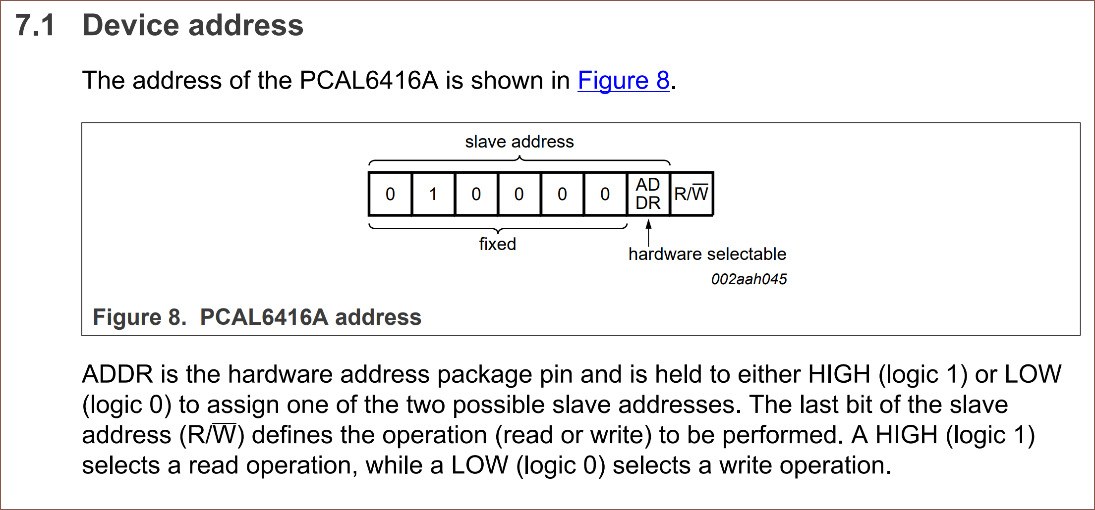 The cheapest one that allows 8 addresses is £1.94 and a 4x4 package. It's a bit of a squeeze but it fits.
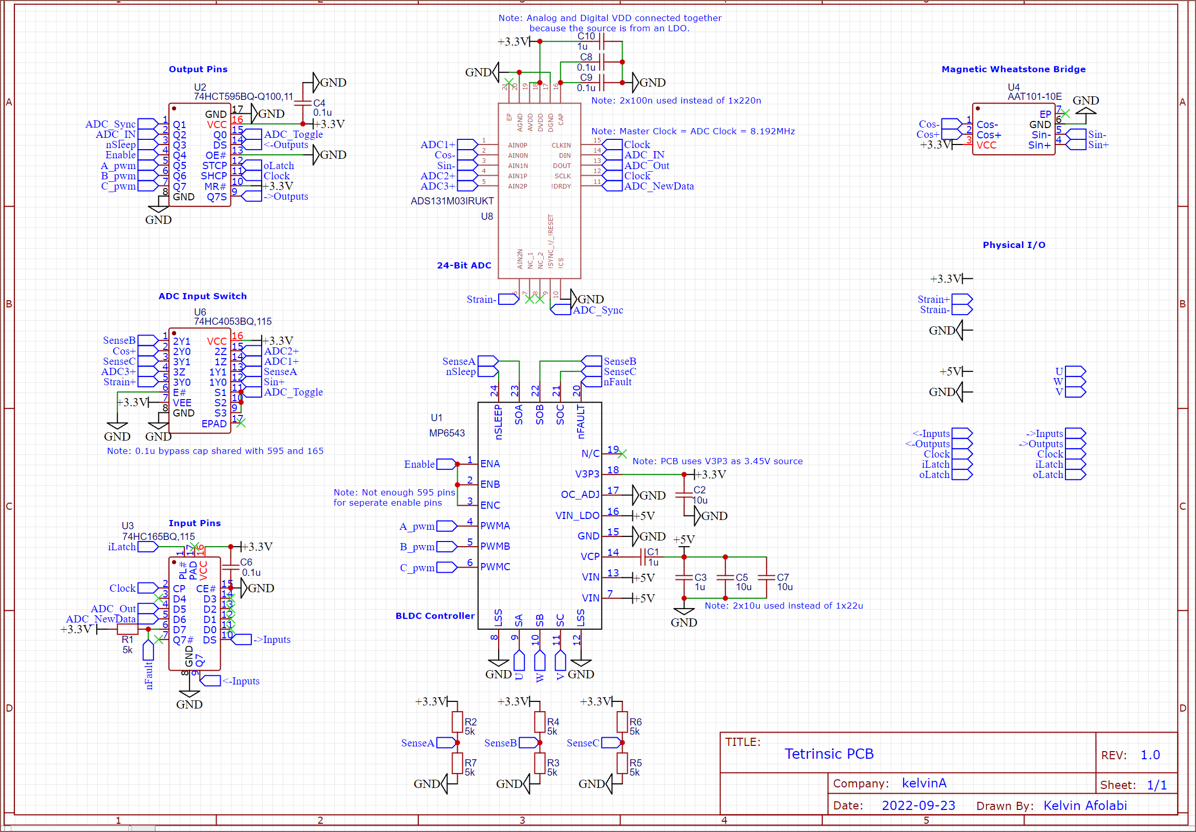 Ok. I've spent the past 2 days drawing up this schematic. The license is going to be under some permissive option but I've just been reading datasheets and connecting the dots so...
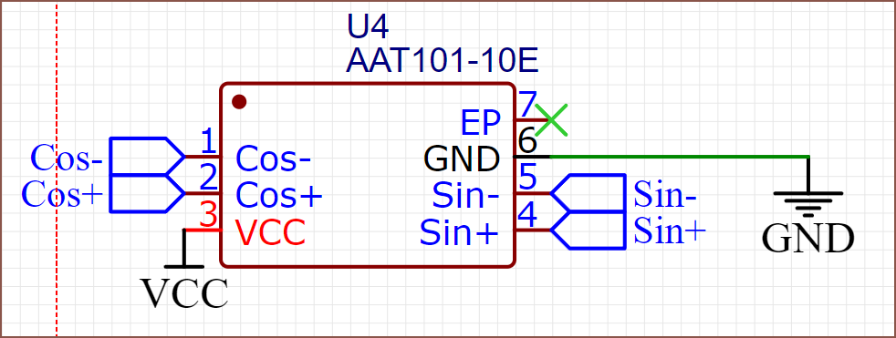 Ok that's 1 chip down.
 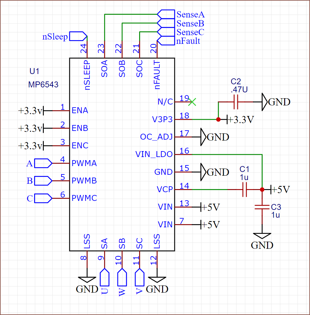 Is that everything? Wait a second... aren't those sense pins analog?
 Nouh!! I'll come back to this later.
 Hmm. Ok I'll assume the paragraph is the correct one. But nice! There's a 3.3V regulator in this chip, so I don't have to send that power from the MCU.
 But that's the worst case option.
 By increasing the PCB to 16x16mm, I could get this layout and also have plenty of output pins with the dual 595 chips. That ultrasmall 1.34 is also the only chip that would even fit in that space.
  HAHAHAH. I'd probably have to buy spares with that kind of size.
 I found this, and it's half the cost as well as being the same sized package as the other chips like the 595. I'm kind of worried about the 120 ohm resistance, but I think the ADC has a much higher impedance anyway.
 This is probably a much less riskier run, and I just had to increase the board width to 20mm.


 uhhhh... CAN'T I USE THE CLOCK??? I think I'm gonna risk it and go down to 1 595--
 No I can't; the time period is too long.
 Do I even need a chip select pin? Reads relevant part of datasheet. No I don't, because the 595/165 means that it's as if each chip now has it's own MOSI and MISO line instead of sharing.
 I really should just make the board wider to accomodate for wider ribbon cables. It doesn't even make that much of a size difference for this currently-untested 4 degree slope (for Finger4 on
  I don't know what to call this second latch pin so I've named it "Load".
 Oh, there is. What MASSIVE capacitor is that though?? I was wondering why the 5V capacitor was never specified. Is it like the large one used for stepper drivers?
  Ah, a schematic. It's a 100u, 35V capacitor? And I assume the other 3 are for something analog-smoothing related? I don't remember something large like that on the SmartKnob View. It's a shame I could only find an interactive BOM and not the schematic. Anyway, it seems that:

 This is because it doesn't seem that there's a merge between a linear slide potentiometer and a rotarty encoder, so this device is now just "Tetrinsic". Actually, drop the "encoder" since I my other project titles aren't "

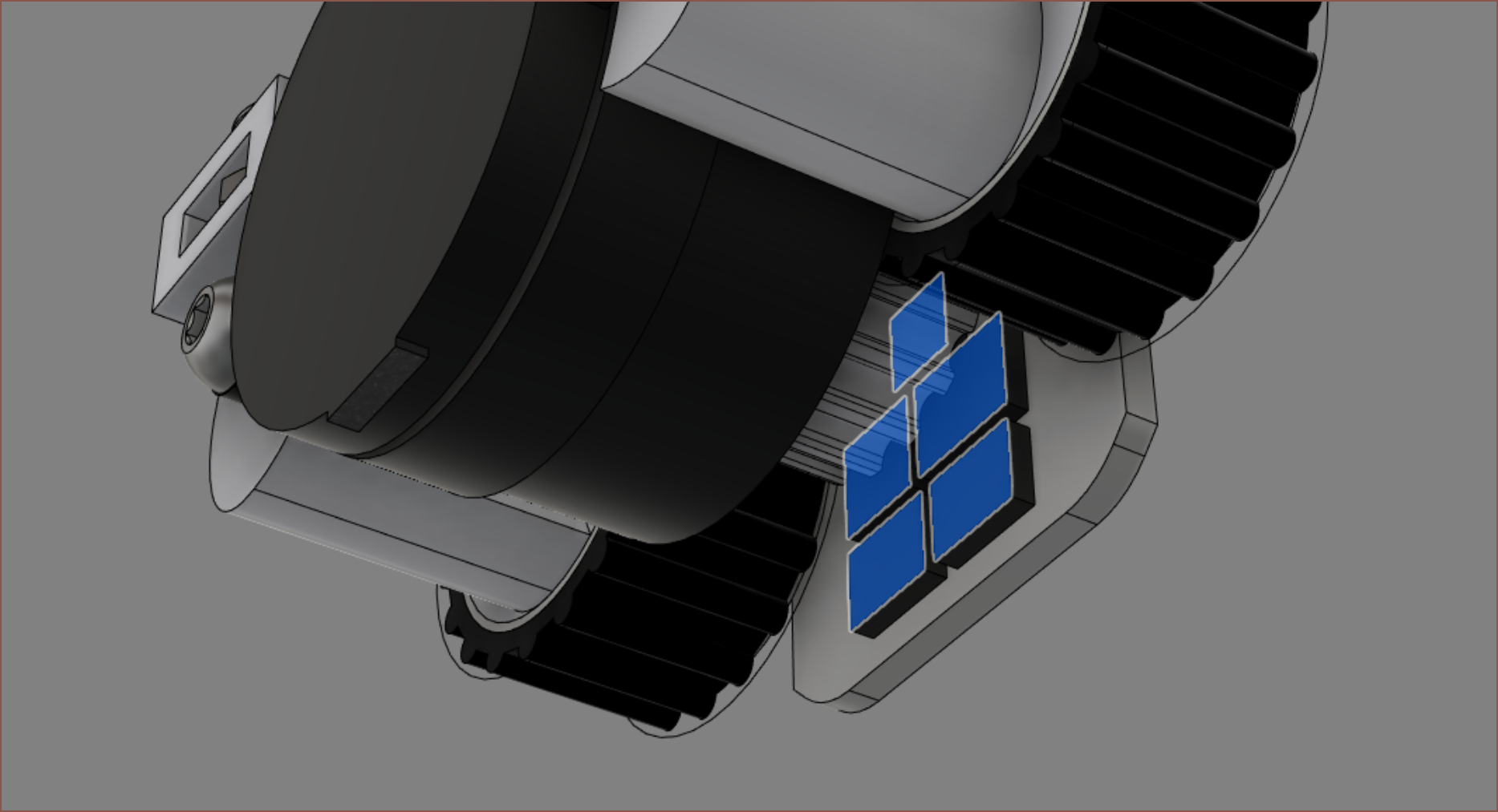 It's pretty close, but there's enough surface space for the 5 chips. I also dug around the datasheets to deduce that the MP6543 needs 4 output pins and the 24-bit ADC needs 5? Looking at the datasheet, I'm hoping that I can have the master clock and the SPI clock connected together, reducing my required output pins to 4.
 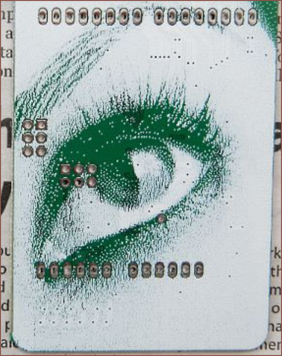 White enough for my science. Wait, that means that I could totally get "white PCBs with green silkscreen" by just inverting the normal silkscreen. I'll remember that.
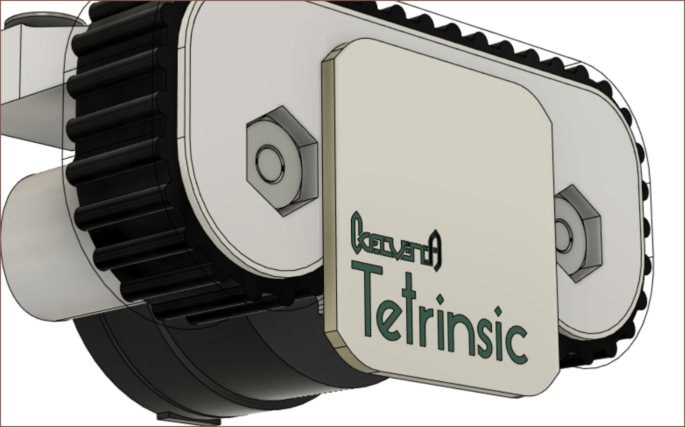
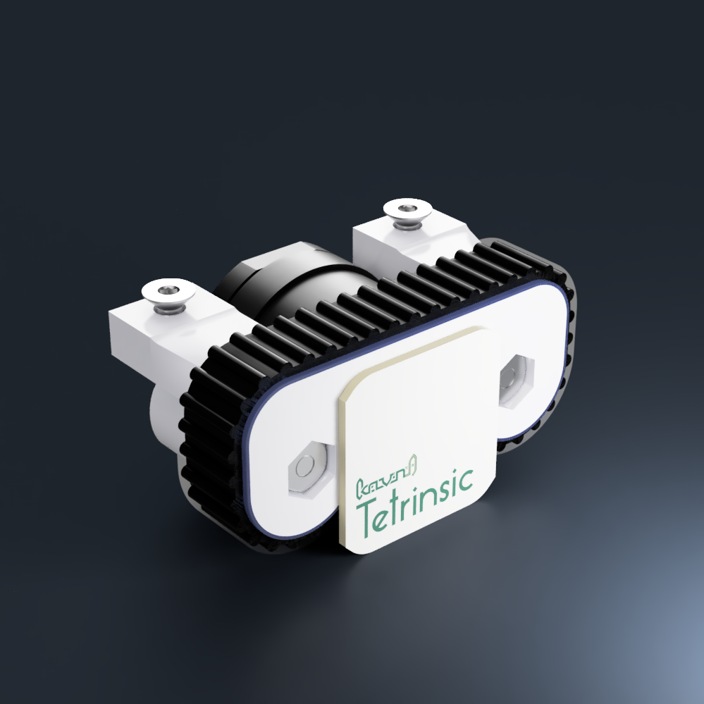 I wonder how far off this render is from looking like the "future first proof of concept" now. That was a roundabout way of saying that I think I'm getting close to a design that will actually exist in the real world.
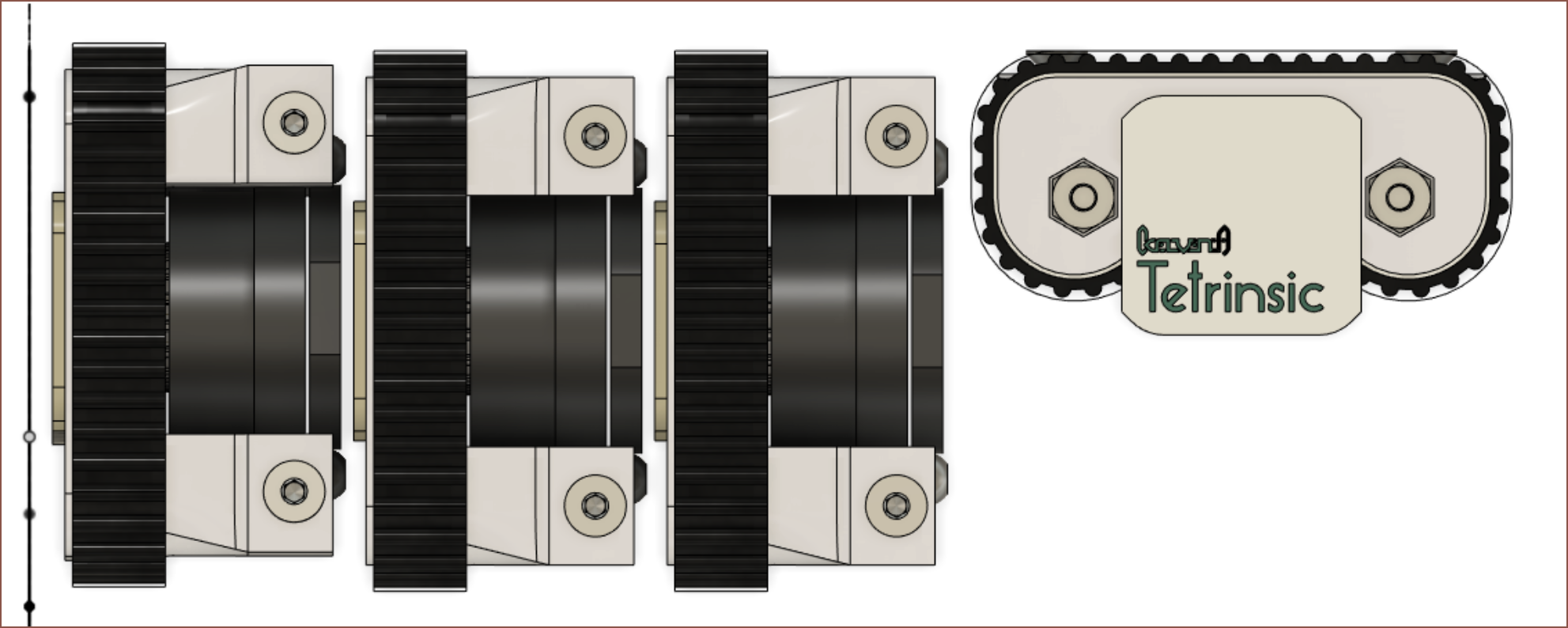 It's going to be pretty close, but I'd be pretty satisfied if I can get this. Actually, I'm somewhat suprised that I can DIY something this unproven yet so professional looking run. I wonder if I should add 3 dots in the top right to make the board look even more advanced though.
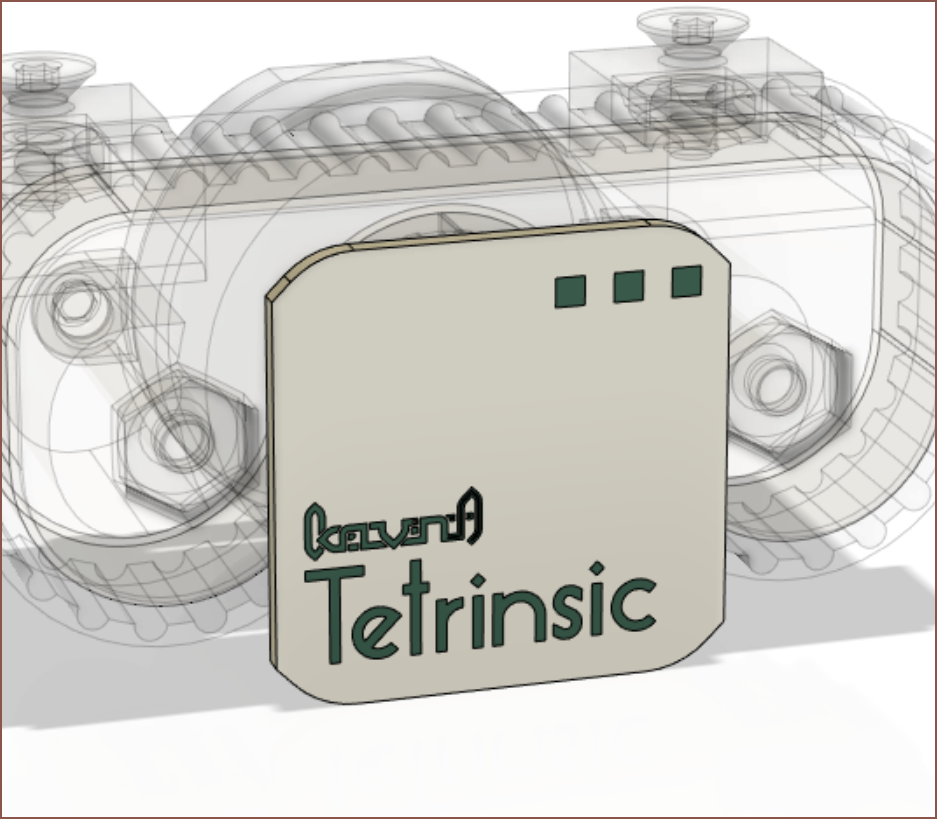 It certainly looks a lot less plain.
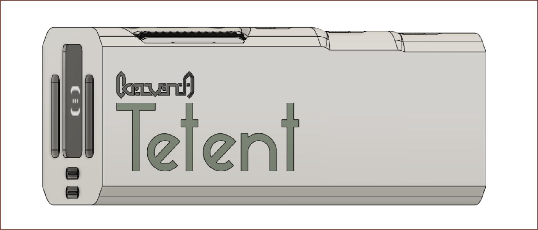 I'll pass because the branding looks perfectly good as is on Tetent.
 The concept uses an 2.8" square display with outter dimensions of 83x60x20mm. I just put something together that looked about right. I don't use smarthome stuff so I wouldn't know if the screen needs to be larger or something. Obviously, similar rotary encoder interfaces (like microwaves and FDM 3D printers) would be something similar looking to the above.

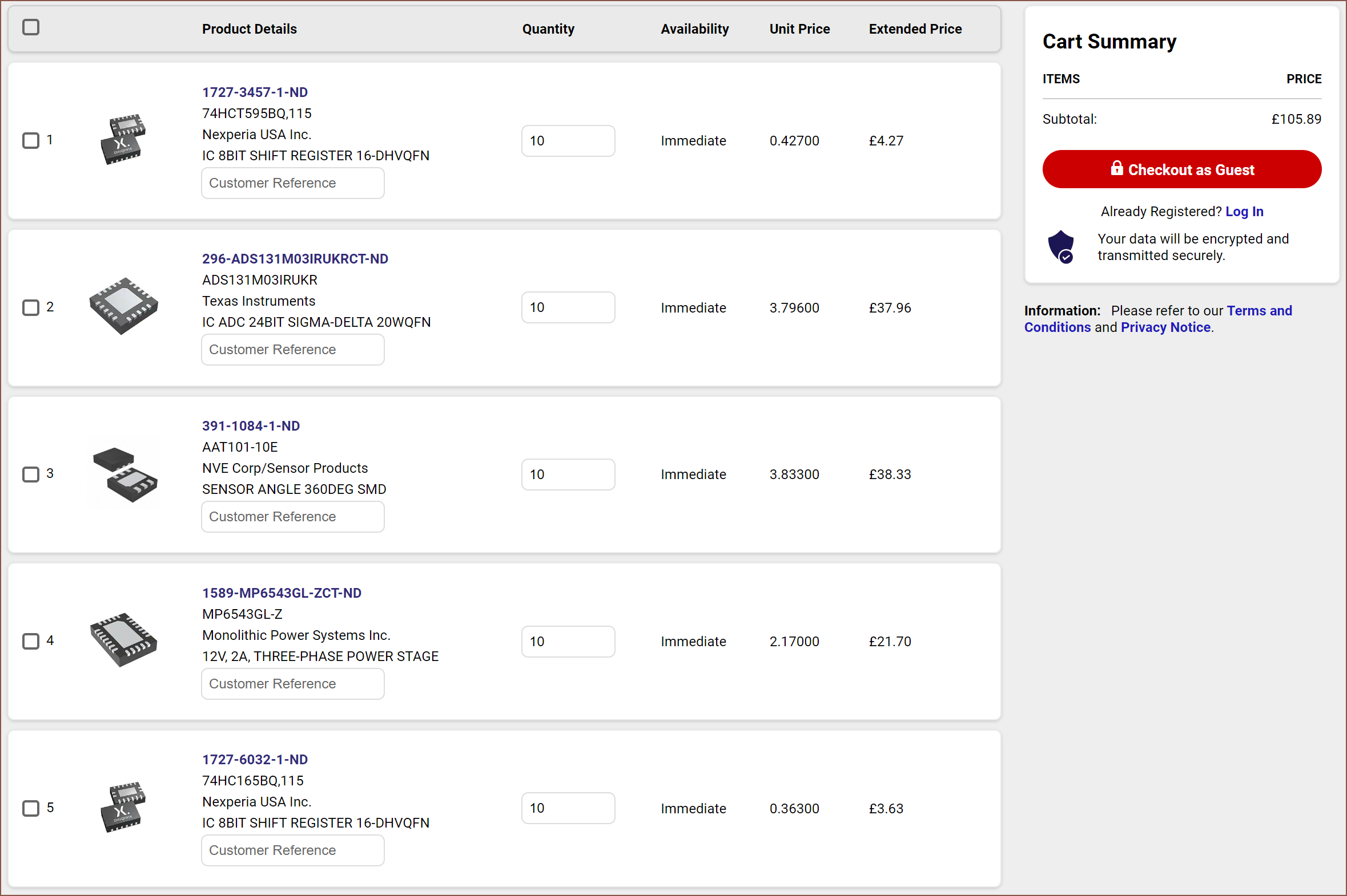 Yikes. This took 8 hours to curate. At least now I know I'm creating a switch that's likely to be >£15 per each. Considering that many ergo keyboards, the Twiddler3 and the Charachorder all cost north of £150, this isn't too terrible. Behind the monitor, the input method is probably the second most important part of a computer system.
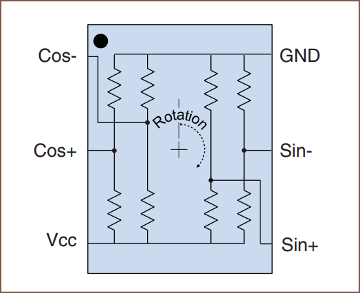 Now, I was looking at that and thinking "hmm didn't quite a few 24 bit ADCs come with more than 1 channel?"