update: this truckload of treasure was Craigslisted onto a stoked local person and his father, both of whom were excited for the possibilities. Consider giving away your old stuff, you might make someone happy.
Danica and I are preparing to move east to pursue new and interesting opportunities. As part of this transition, we're doing a good bit of downsizing. I've decided to rid myself of a lot of the random electronics (and electronics-adjacent) junk I've collected over the last few years. Some of this isn't worth much, but you may find some useful gems and I'm not interested in splitting the lot up at this point. If you are interested, live in the US, and are willing to cover postage, I will send it to you for free.
I'm still figuring out exactly what the box will contain, but at a minimum:
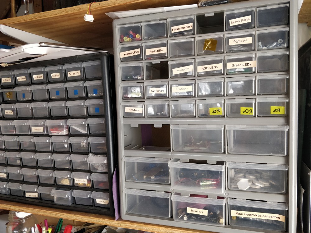
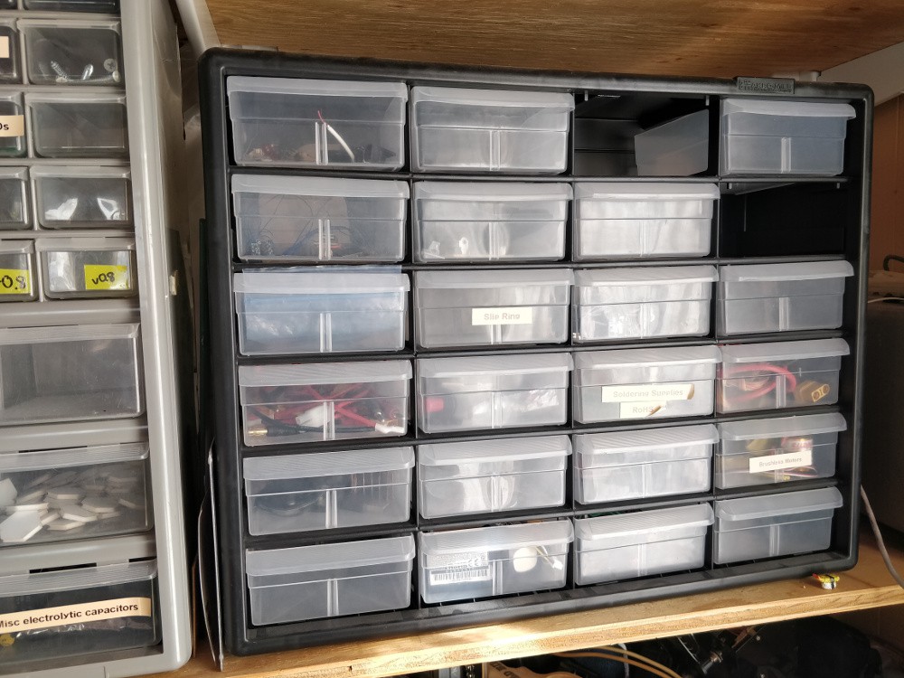
three Akro-Mils clear sliding drawer bins filled with random and interesting parts
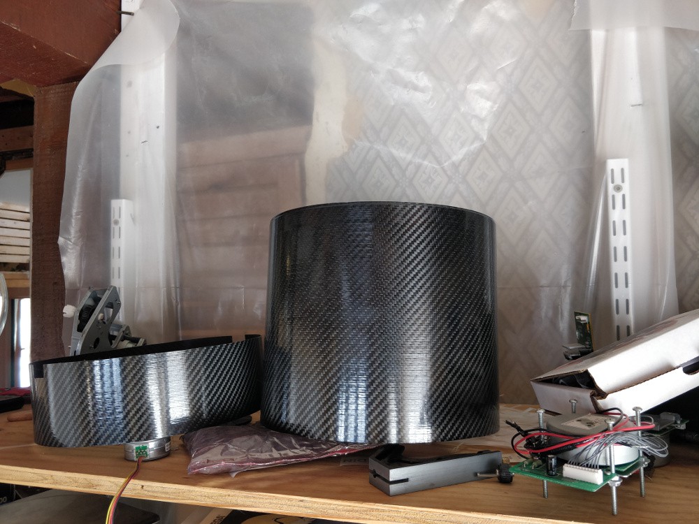
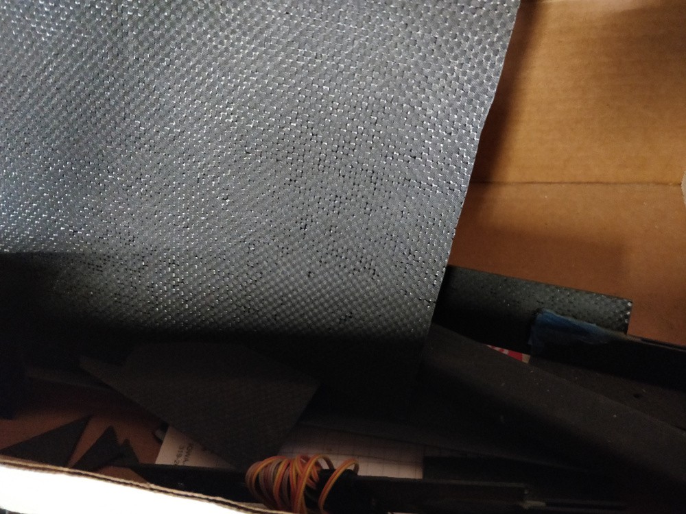
a selection of DragonPlate CFRP scraps of various sizes
two somewhat flexible large diameter CFRP tubes
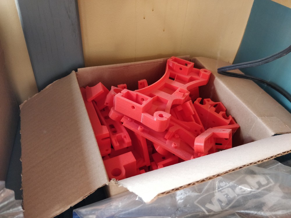
a partial Reprap Wilson II 3D printer (all the 3D printed parts plus black anodized extrusion, but nothing else)
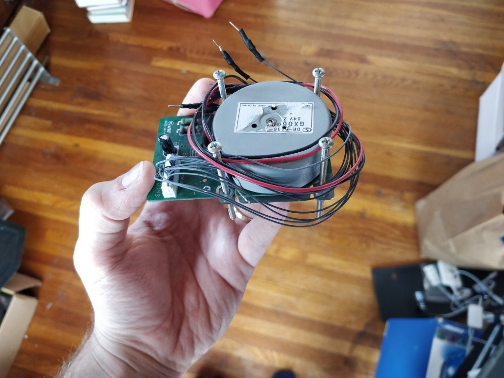
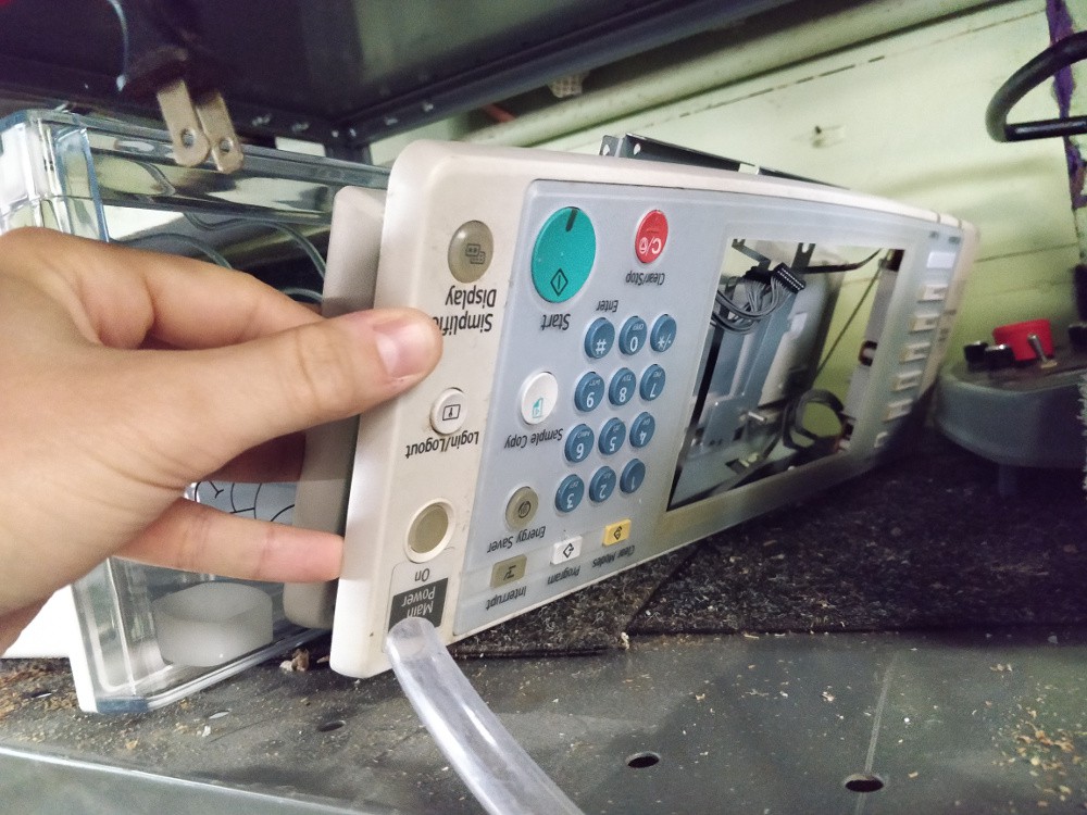
all of the interesting bits out of an office photocopier: gears, shafts, steppers, servos, first surface mirrors, sensor, control panel, etc.
a PiDP-8 kit, with the switch soldering already done
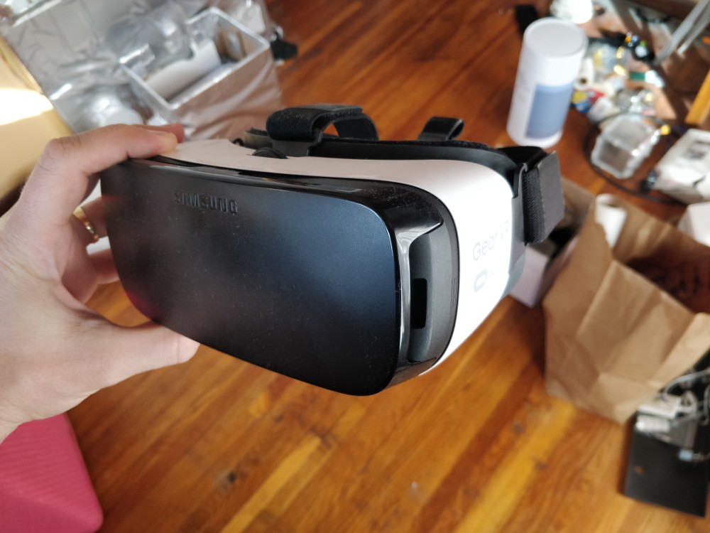
a samsung galaxy gear VR headset, designed for a phone I never owned
my old modified toaster oven reflow setup, which works but you should be careful with and probably reprogram (it's powered by an Arduino of some kind)
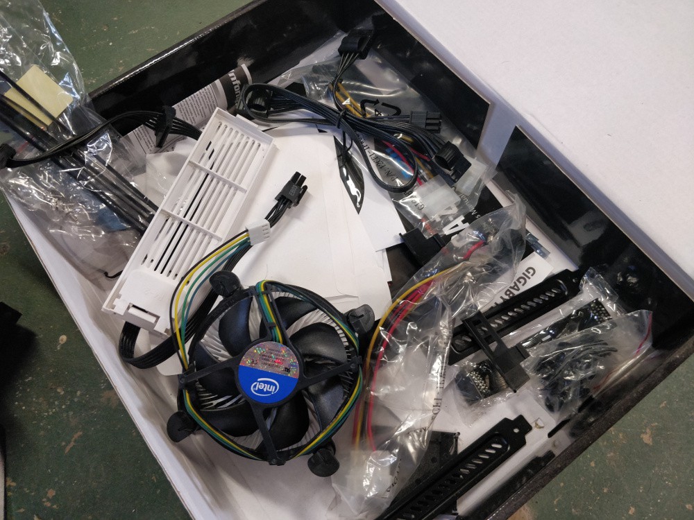
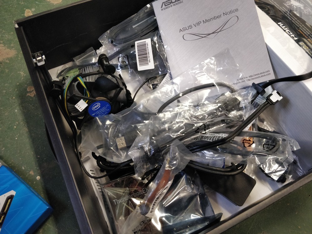
a selection of homebuilt PC extras, including a few stock Intel coolers and lots of misc cables
a beefy-AF transformer of unknown rating
a nice pair of HeNe (632nm) laser safety goggles
a few under-counter LED lights
the guts from an old-school industrial 900 MHz industrial data radio
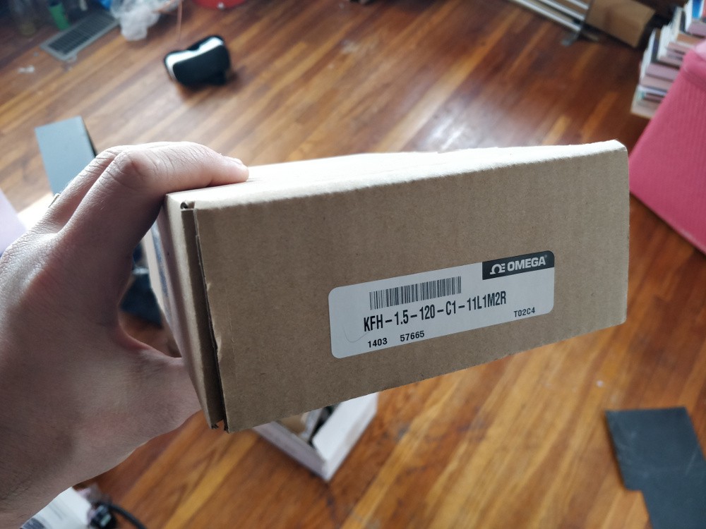
a box of ~10 Omega pre-wired strain gages (these list at $10 ea!)
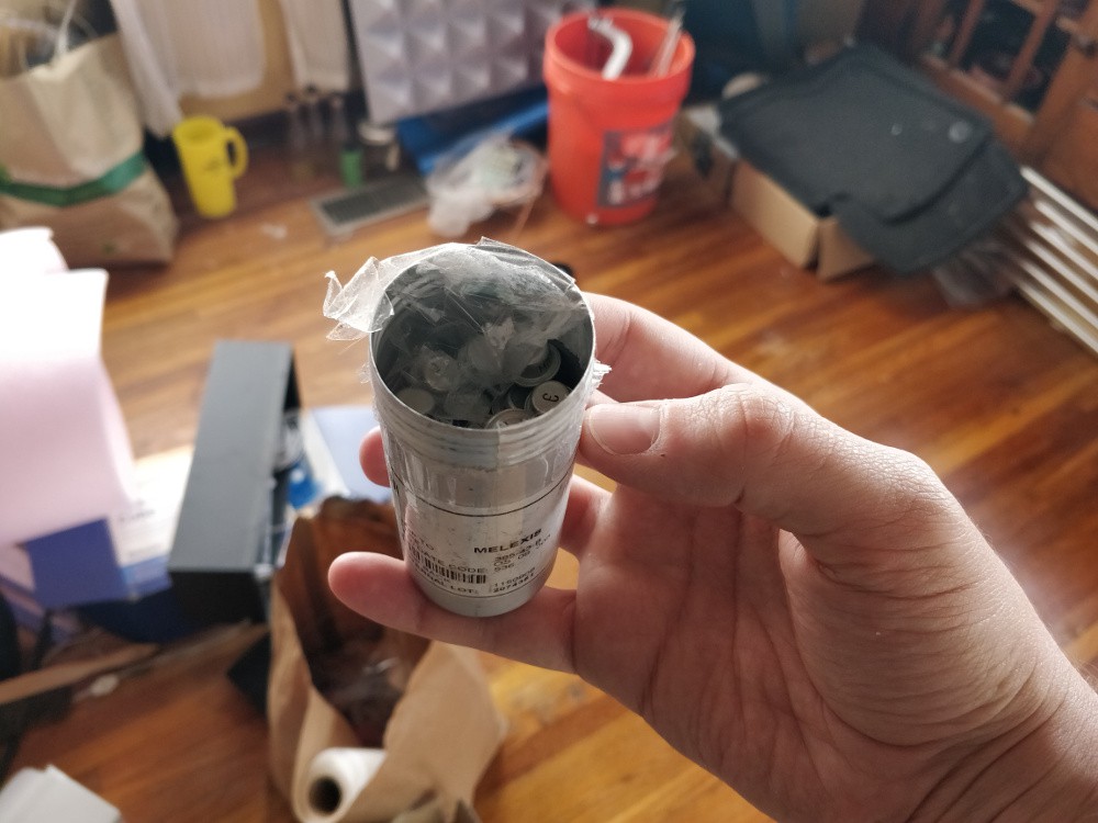
a pile of germanium transistors
My guess is the box will weigh in the 20-30 kg range, so UPS thinks it will cost around $100 to ship. If you're interested, write me a note: zachary dot fredin at gmail dot com. Otherwise, most of this will become e-waste by late May.
My feelings on 'badgelife' are neutral. I like that more people are getting in to PCB art and electronics. But personally, the only electronic conference badges I really enjoy are the ones I build myself (or at least physically customize). Most of the badges I get are worn for a few hours until they get too heavy and annoying, and then they become e-waste. And it's not my preference to let someone else design the hardware and spend my time hacking by writing code. That's my least-favorite part of any project!
But the trend towards taking copyrighted work, mashing it into an EDA tool, and building a few hundred badges or add-ons to sell online or at a conference? I find that lazy and disrespectful. Okay, copy some popular cartoon figure and make a few boards for yourself. But don't sell them en masse! Please, at the very least, come up with an original design!
edit: thank you all for reminding me why hackaday.io comment sections are amazing, I'm sure the same thing would *not* have happened on the main site :-/
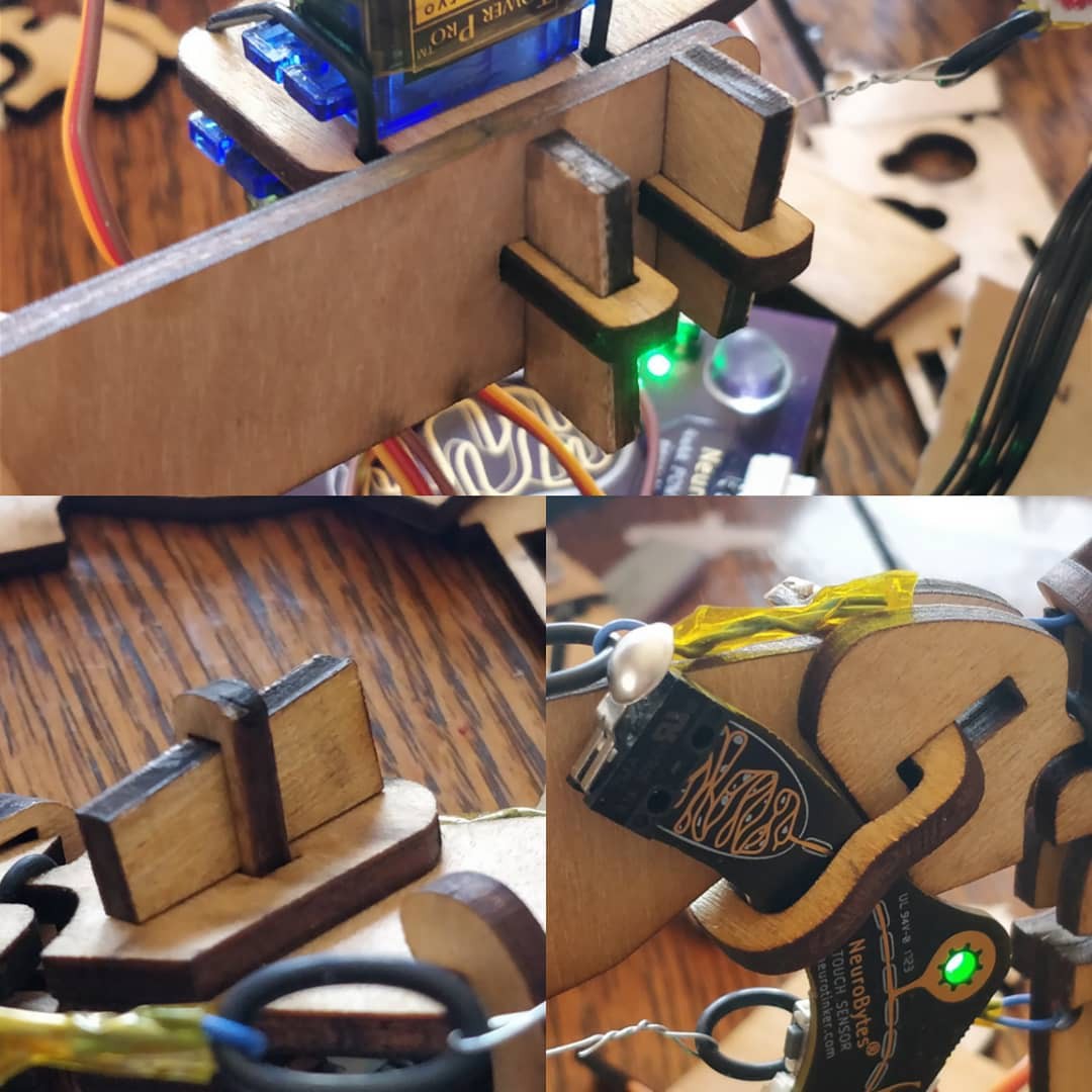
On a few occasions I have had the need to secure something to a flat bit of laser cut wood. In all cases, I created precise shapes that allow me to rigidly and accurately grip the object while not depending on the exact dimensions of the cuts themselves. The method requires final alignment to be performed during assembly, but does allow for post-assembly re-alignment and doesn't require any adhesives or fasteners. A few examples from a recent #NeuroBytes patellar reflex model iteration:
The top image is a simple T-joint, used to connect two right angle bits of 3.2mm aircraft plywood. The middle piece goes through the base in two spots and has cutouts for wedges, which are inserted and tightened during assembly to pull the joint tight. The angle isn't exactly 90 degrees due to the aforementioned kerf taper, but it works well enough for this application (a mounting plate for a demonstration model).
The lower images show a second joint from two sides. In this case, I needed to precisely locate a Touch Sensory Neuron with respect to the patellar tendon (the blue wire and O-ring assembly). I didn't want to modify the circuit board at all, and the exact orientation of the snap-action switch at the end of the PCB is critical to proper functionality of the model. Since the tendon is made by the end user and may vary slightly in length, part of the leg adjustment process requires the switch orientation to be adjustable, lockable, and potentially re-adjustable down the road. A cross plate with a few machine screws would have done the trick, but this method avoids the need for a screwdriver and easily lost hardware. I call the weird curved clampy bit the 'connector plate'. Not a great diagram but hopefully you get the idea. The wood base has several layers, and you have to imagine that the leftmost layer extends out towards the viewer along the dashed line. That way, when a wedge is inserted into the rectangular 'wedge goes here' slot, it pushes the upper bit of the connector plate to the left as its driven into place, clamping the board securely in place. I really should reference a side view or 3D model with this sectional image, but... here we are.
During installation, the connector plate slides in from the bottom (which is open and rotates into position, pivoting on the lower 'catch'. To ensure clearances with the holes in the wood base, I keep track of the connector plate's position extremes on the wood base using guides in Inkscape. Rotating the connector plate like this is a synch if you just move the cross symbol to change the center of rotation to the bottom contact point: Note that in the third frame, I actually translated the connector plate up a bit so one of the corners can clear. This is much easier during real life assembly; you really just need to be sure everything clears at all points during the rotation/translation, as manual assembly makes combining both movements quite intuitive.
I used a similar method to hold the servos on for the latest NeuroBuggy design. Again, I needed to secure an object (in this case, a continuous rotation servo) to a flat laser-cut sheet. The object needed to be adjustable (toe angle!) and quite secure, but also removable. The connector plate is bigger but otherwise similar to the previous example -- it slides in from the rear of the car, rotates into position, and gets secured by a wedge:
This method is still very much a work in progress. I think a lot of optimization could be done to reduce the material requirement and cut length; for example, the width ratios of the tenons and slots could be standardized (probably based on a woodworking joinery book's advice), and the curved shape of the connector plate itself could probably be generated parametrically once a few constraints are figured out. The wedges are also probably beefier than needed and the angles could be optimized. But it's a good start -- feels good to assemble something without glue or fasteners!
Collaborated with Scott Anderson on the design and most of the construction. He also loaned me the suit. Had a ton of random help building it, and even more dragging it around campus (made it 6 miles, nothing broke). 1-week(ish) project.
Workbench Party Lightzzz (2013)
They turn white too for general illumination, but that is lame.
Toaster Oven Reflow (2014)
Simple, effective, and slightly dangerous. Fuses (thermal and electrical) are a must.
The Big Stupid Raft (2009ish?)
Found some thoroughly used pine T&G flooring, paired it up with a few old sheets of expanded polystyrene, a bunch of freshly chopped aspens, an 8-horse outboard, two chairs, and a couple of tiki torches. Made it around the lake, no regrets.
Batman v. Superman Rock'em Sock'em Robots (2007)
A bit larger than life size, fully functional, put this together in about a week. I built most of the robots and designed/machined the mechanism, and had an amazing amount of help from a number of other kindly folks.
Thank you for liking my #PERSEUS-9 homemade mobile 6502 computer ! A few days ago I made a video of a home-built AD converter working with this computer and linked it at the end of the project detail.
Thank you for your comment. Developing the control firmware for the LEDs was hard work, but it was worth it. With this design in a die-cast case, I think it will still be good 20 years from now.
Thanks for following my MAX32660 Motion Co-Processor project! We have the I2C async slave bus working, the master I2C bus working at 1 MHz, and the MAX32660 is spewing quaternions at 1 kHz to the master (host). We'll be describing our recent progress in an updated log soon.
Awesome! You have a neat project there. I'm thinking about the MAX part for a project and am just starting to investigate toolchain and so forth. Any advice, having used the part for awhile?
Like most MCUs, there are lots of gaps in the available HAL/APIs. We had to do a lot of work to get async I2C and slave I2C to work robustly, for example. I suspect, like most HALs, the APIs work just well enough for the examples/demos but for general application they require significant rework. But the Eclipse SDK is actually among the easiest to install and use of all those I have tried, so kudos to Maxim on this point. And the device can achieve low power operation, so it is an attractive candidate as a small co-processor despite the typical HAL problems.
Hey Zach, I was diverted here by Google when examining Ultrasonic Flow Measurement. I'm coming up with an Enhanced Enteral Feed Pump for my disabled son who is tube fed. The project starts out with the ESP32 and a 5" Spi Display. I added an RTC for timekeeping because I wanted automatic rate change at certain times of the day. Lots of user interface buttons made but one of the things his OLD pump does is detect a flow loss in the feed tube. From what I can gather, it has a pair of transducers potted into the tube path that "looks" at the liquid in the tube. I have no idea how the old pump processes the info though. I'm guessing Ultrasound but not sure which method. Other than that, the rate of flow is via a roller pump on rubber tubing but there is an encoder I can watch to get revs/mL. Any ideas?


 zakqwy
 Benchoff
 Tindie
 Anool Mahidharia
 Hackaday
 Sophi Kravitz
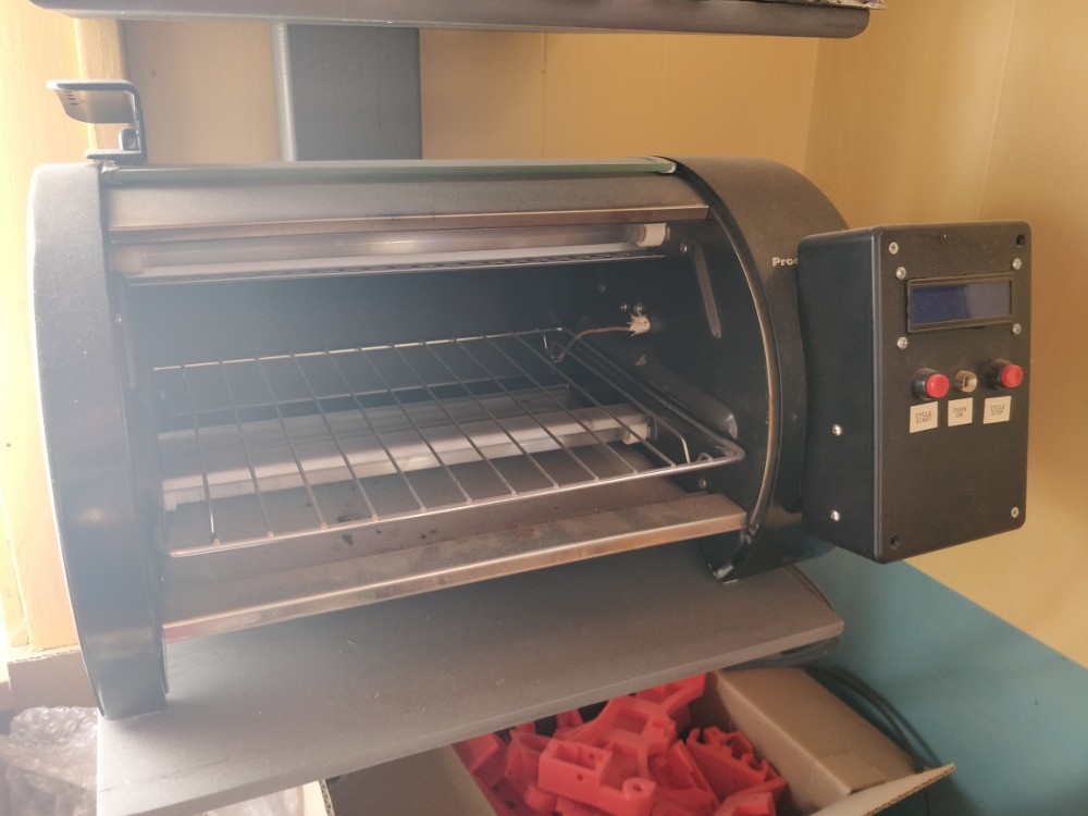

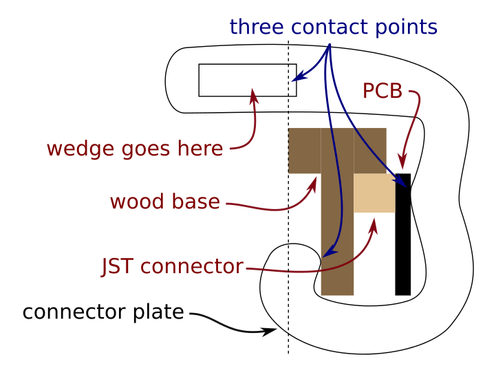 Not a great diagram but hopefully you get the idea. The wood base has several layers, and you have to imagine that the leftmost layer extends out towards the viewer along the dashed line. That way, when a wedge is inserted into the rectangular 'wedge goes here' slot, it pushes the upper bit of the connector plate to the left as its driven into place, clamping the board securely in place. I really should reference a side view or 3D model with this sectional image, but... here we are.
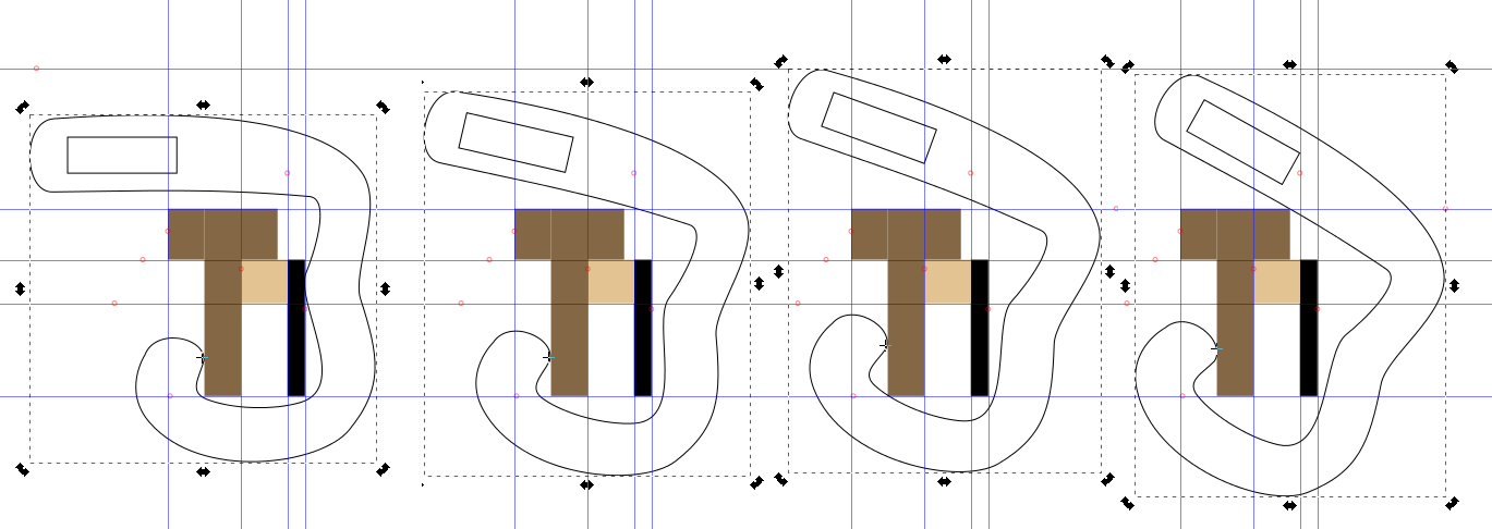 Note that in the third frame, I actually translated the connector plate up a bit so one of the corners can clear. This is much easier during real life assembly; you really just need to be sure everything clears at all points during the rotation/translation, as manual assembly makes combining both movements quite intuitive.
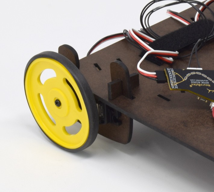
 ronald
 Max.K
Max.K deqing
 BLANCHARD Jordan
 Bertrand Selva
 PP
PP methodicalmaker_
 makeTVee
 Austin Allen
 b0nsaibear
 Etholannan
 jeremy.geppert
 kerry clancy
 Simon Liu
 junkotron
 mircemk
 Alex Nunn


Thanks for the Like/Follow of my #HP34401A Meter Command Line Control Software Tool project.
Bob